EP0963233B1 - Strainer arrangement for straining liquid from a mixing arrangement - Google Patents
Strainer arrangement for straining liquid from a mixing arrangement Download PDFInfo
- Publication number
- EP0963233B1 EP0963233B1 EP98901626A EP98901626A EP0963233B1 EP 0963233 B1 EP0963233 B1 EP 0963233B1 EP 98901626 A EP98901626 A EP 98901626A EP 98901626 A EP98901626 A EP 98901626A EP 0963233 B1 EP0963233 B1 EP 0963233B1
- Authority
- EP
- European Patent Office
- Prior art keywords
- strainer
- shaft
- arrangement according
- pipe
- gaps
- Prior art date
- Legal status (The legal status is an assumption and is not a legal conclusion. Google has not performed a legal analysis and makes no representation as to the accuracy of the status listed.)
- Expired - Lifetime
Links
- 239000007788 liquid Substances 0.000 title claims abstract description 13
- 238000004140 cleaning Methods 0.000 claims abstract description 28
- 239000002245 particle Substances 0.000 claims abstract description 11
- 239000007787 solid Substances 0.000 claims abstract description 4
- 238000011084 recovery Methods 0.000 description 4
- 238000002485 combustion reaction Methods 0.000 description 3
- 239000003546 flue gas Substances 0.000 description 2
- 238000002347 injection Methods 0.000 description 2
- 239000007924 injection Substances 0.000 description 2
- 238000009434 installation Methods 0.000 description 2
- 238000000034 method Methods 0.000 description 2
- 238000010276 construction Methods 0.000 description 1
- 238000009826 distribution Methods 0.000 description 1
- 238000010438 heat treatment Methods 0.000 description 1
- 238000004519 manufacturing process Methods 0.000 description 1
- 239000000463 material Substances 0.000 description 1
- 239000000203 mixture Substances 0.000 description 1
- 230000003014 reinforcing effect Effects 0.000 description 1
- 238000007790 scraping Methods 0.000 description 1
- 239000000243 solution Substances 0.000 description 1
- 229910001220 stainless steel Inorganic materials 0.000 description 1
- 239000010935 stainless steel Substances 0.000 description 1
- 239000000126 substance Substances 0.000 description 1
Images


Classifications
-
- B—PERFORMING OPERATIONS; TRANSPORTING
- B01—PHYSICAL OR CHEMICAL PROCESSES OR APPARATUS IN GENERAL
- B01D—SEPARATION
- B01D29/00—Filters with filtering elements stationary during filtration, e.g. pressure or suction filters, not covered by groups B01D24/00 - B01D27/00; Filtering elements therefor
- B01D29/11—Filters with filtering elements stationary during filtration, e.g. pressure or suction filters, not covered by groups B01D24/00 - B01D27/00; Filtering elements therefor with bag, cage, hose, tube, sleeve or like filtering elements
- B01D29/31—Self-supporting filtering elements
- B01D29/33—Self-supporting filtering elements arranged for inward flow filtration
-
- B—PERFORMING OPERATIONS; TRANSPORTING
- B01—PHYSICAL OR CHEMICAL PROCESSES OR APPARATUS IN GENERAL
- B01D—SEPARATION
- B01D29/00—Filters with filtering elements stationary during filtration, e.g. pressure or suction filters, not covered by groups B01D24/00 - B01D27/00; Filtering elements therefor
- B01D29/62—Regenerating the filter material in the filter
- B01D29/64—Regenerating the filter material in the filter by scrapers, brushes, nozzles, or the like, acting on the cake side of the filtering element
- B01D29/6469—Regenerating the filter material in the filter by scrapers, brushes, nozzles, or the like, acting on the cake side of the filtering element scrapers
- B01D29/6484—Regenerating the filter material in the filter by scrapers, brushes, nozzles, or the like, acting on the cake side of the filtering element scrapers with a translatory movement with respect to the filtering element
Definitions
- the invention relates to a strainer arrangement for straining liquid from a mixing arrangement, such as a mixing tank, for black liquor containing solid particles of ash.
- a mixing arrangement such as a mixing tank
- black liquor containing solid particles of ash The ash in the black liquor is formed during combustion of black liquor and is separated from the flue gases and is mixed with new black liquor for introduction into the combustion installation which usually consists of a recovery boiler.
- a recovery boiler For re-introducing the ash into the recovery boiler, it is important that the ash is thoroughly mixed with the black liquor which is to be combusted and that larger particles of ash, which may obstruct the nozzles for injecting the black liquor into the recovery boiler, are strained off using a suitable arrangement, and the invention relates to such a strainer arrangement.
- mixing tanks and usually consist of a vessel with agitator(s), provided with liquor inlet(s), liquor outlet(s), ventilating pipe(s), ash inlet(s) and in most cases a heating arrangement.
- agitators use has as a rule been made of slow-moving agitators with arms which sweep along the perimeter of the mixing tank and create no more turbulence than allows larger particles to settle to the bottom zone. The lowest arms of the agitator are therefore made in the form of a scraping unit which works close to the bottom and performs mechanical treatment there of the settled material which is crushed into smaller particles which can gradually rise up to a higher level in the tank and pass out through the outlet.
- the injected liquor In order that the liquor distribution in the combustion chamber takes place in a trouble-free manner, the injected liquor must not contain particles which are too large because these may block the injection nozzles.
- the liquor is therefore usually strained through a fixed strainer known as a perforated plate which is placed in front of the outlet of the mixing tank.
- the strainer plate which constitutes a part of the outside of the tank and is lowered into vertical holders and which covers a large number of outlet openings, strains off larger particles and functions well as long as the strainer plate has not been obstructed. From time to time, however, it has to be cleaned and this can be done by lifting it up and subjecting it to cleaning outside the mixer or by liquid being allowed to flow in counter-current or by other means. However, this is a complicated procedure which disrupts production. For this reason, it has long been desirable to be able to produce a strainer arrangement which is cleaned automatically and without interrupting operation.
- a strainer arrangement for straining liquid from a mixing arrangement e.g. a mixing tank, for black liquor containing solid particles of ash
- a mixing arrangement e.g. a mixing tank
- strainer arrangement is characterized in that it comprises a strainer pipe with axially, preferably vertically, extending gaps for radial inflow into the strainer pipe of liquid, and also cleaning pins in the gaps mounted on an axially movable shaft in the strainer pipe.
- the cleaning pins may be mounted on the shaft via rotatably suspended holders resembling wheels.
- the cleaning pins may have a round or angular cross-section.
- the gaps should be distributed uniformly around the perimeter of the pipe and expediently total twenty-four in number.
- the gaps expediently have a length of roughly 500 mm and/or a width of roughly 8 mm and are preferably arranged in a number of groups, expediently four groups, one above another.
- the movements of the shaft can be brought about with the aid of an electric motor or pneumatically or hydraulically.
- an extension shaft coupled to the uppermost part of the shaft is provided with trapezoidal threads to make worm-gear driving possible.
- a seal is expediently arranged around the shaft at the upper end of the strainer pipe.
- the strainer pipe may be arranged in a vertical space on the outside of the tank wall, freestanding from the mixing tank or inside the latter, or it may consist of a strainer plate on the tank wall.
- Fig. 1 shows a mixing tank or mixer 1 in vertical section.
- the tank is usually filled with liquid to the level 2. Filling is carried out continuously but, for the sake of simplicity, the arrangements for filling have been omitted.
- the vertical section has been made through the row of outlet openings 3 which are formed in the casing wall of the container 1 and which are located in a row one above another and number four in the drawing.
- Located outside the outlet openings 3 is a vertically positioned outlet container of almost semi-circular cross-section, which delimits the outlet openings 3.
- Fig. 2 shows a horizontal section through the tank according to Fig. 1.
- the same reference numbers as those in Fig. 1 apply for this figure also.
- a reinforcing stay 8 which is arranged at appropriate places and is necessary in order to provide the construction with stability.
- Fig. 3 shows a detailed view of the cleaning arrangement according to the invention.
- the vertically movable shaft 6 is indicated, on which a holder 9 which bears the cleaning pins 10 is fastened.
- the cleaning pins 10 run in slits or gaps 11 in the strainer pipe 5.
- the holder 9, which resembles a wheel, is clamped with a given clearance fit between two brackets 12 which are in turn screwed tight on the shaft 6 with the aid of conical bolts.
- the cleaning pins 10 are screwed tight in the holder 9. These pins 10 must be mounted after the shaft 6 with the associated holders 9 has been guided into the strainer pipe 5.
- These cleaning pins 10 are expediently of circular cross-section. They may, however, also be of angular cross-section, e.g. rectangular or triangular, because they can then function as a knife when they are guided up and down in the strainer pipe 5.
- Fig. 4 shows a horizontal section through the shaft 6 with holder 9 fitted on, into which cleaning pins 10 have been screwed. These cleaning pins 10 number twenty-four in the present case.
- the cleaning pins 10 preferably have a diameter of roughly 8 mm and they are guided up and down in the gaps 11 with a stroke of expediently 0.5 m. If the cleaning pins 10 are of angular cross-section, a slightly larger gap opening is required at one end of the gaps so that the pins can be screwed in despite the non-round shape.
- the holder 9 has been arranged on the shaft 6 with given clearance so that it can be rotated to a certain extent around the shaft. This is to facilitate mounting of the cleaning pins 10.
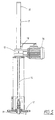
- Fig. 5 shows partly in section the driving arrangement for the upward and downward movement of the shaft 6.
- This shaft 6 is guided out through a flange 13 and is coupled together with an extension shaft 14 with trapezoidal threads.
- This shaft extension 14 constitutes a part of a worm gear 15 which is driven by an electric motor 16.
- Above the worm gear 15, the shaft extension 14 moves in a tube 17.
- upper and lower indicators 18 which show the upper and lower position of the shaft extension 14 and with this also the upper and lower positions of the cleaning pins 10.
- a rubber seal 19 Arranged in the flange 13 through which the shaft 6 extends is a rubber seal 19 to prevent corrosive liquor entering the space above the flange 13 and causing damage.
- Fig. 5 shows the lower position of the shaft 6. In the upper position, the shaft 6 thus extends all the way up to close to the worm gear 15.
- a hydraulic or pneumatic driving arrangement can be installed. Driving takes place automatically, the stroke is defined by the indicators 18 and the interval between the upward and downward movements is set with the aid of a control unit. After movements have been performed, it is expedient that the shaft remains in the upper position which is a rest position. This is indicated by the upper sensor 18 being lit up.
- the time taken for a stroke movement is usually roughly 45 seconds.
- the appropriate rest time depends on the composition of the liquor and can be determined only after a test operation period.
- strainer pipe and the cleaning pins are preferably made of stainless steel.
- strainer pipe 5 may also consist of a strainer plate which is mounted in a similar manner as in the prior art but which has vertical gaps for the cleaning pins 10.
- This strainer plate thus constitutes a part of a pipe. It is not necessary either, although desirable, that the cleaning pins 10 are located around the entire circumference. If the strainer pipe 5 consists of only a part of a pipe, it is of course sufficient for the cleaning pins 10 to be limited to a number which corresponds to the gaps in the strainer pipe.
- any larger particles which do not go in through the gaps 11 are crushed. These particles may also consist of a relatively sticky substance which easily becomes stuck in narrow passages. These too are scraped away by the cleaning pins 10 and will be present in such a finely divided state that the injection nozzles which follow are not obstructed.
- the gaps 11 may extend otherwise than purely vertically, e.g. helically. Arranging purely horizontal gaps is another alternative, the shaft 6 then being rotated to and fro in order to move the cleaning pins 10 in the gaps 11.
Landscapes
- Chemical & Material Sciences (AREA)
- Chemical Kinetics & Catalysis (AREA)
- Accessories For Mixers (AREA)
- Filtration Of Liquid (AREA)
- Separation Of Solids By Using Liquids Or Pneumatic Power (AREA)
- Cleaning By Liquid Or Steam (AREA)
- Sampling And Sample Adjustment (AREA)
- Cyclones (AREA)
Abstract
Description
- The invention relates to a strainer arrangement for straining liquid from a mixing arrangement, such as a mixing tank, for black liquor containing solid particles of ash. The ash in the black liquor is formed during combustion of black liquor and is separated from the flue gases and is mixed with new black liquor for introduction into the combustion installation which usually consists of a recovery boiler. For re-introducing the ash into the recovery boiler, it is important that the ash is thoroughly mixed with the black liquor which is to be combusted and that larger particles of ash, which may obstruct the nozzles for injecting the black liquor into the recovery boiler, are strained off using a suitable arrangement, and the invention relates to such a strainer arrangement.
- Mixing ash separated from the flue gases with black liquor which is to be combusted in a recovery boiler is a well-known technique which has been practised for many decades. Various installations for performing such mixing have been designed over the years. Such mixing arrangements are called mixing tanks and usually consist of a vessel with agitator(s), provided with liquor inlet(s), liquor outlet(s), ventilating pipe(s), ash inlet(s) and in most cases a heating arrangement. As agitators, use has as a rule been made of slow-moving agitators with arms which sweep along the perimeter of the mixing tank and create no more turbulence than allows larger particles to settle to the bottom zone. The lowest arms of the agitator are therefore made in the form of a scraping unit which works close to the bottom and performs mechanical treatment there of the settled material which is crushed into smaller particles which can gradually rise up to a higher level in the tank and pass out through the outlet.
- In order that the liquor distribution in the combustion chamber takes place in a trouble-free manner, the injected liquor must not contain particles which are too large because these may block the injection nozzles. The liquor is therefore usually strained through a fixed strainer known as a perforated plate which is placed in front of the outlet of the mixing tank.
- One example of a modern embodiment of a mixing tank is described in Swedish Patent 9600100-3. Good mixing is achieved in this mixing tank with the aid of baffles on the agitator and stationary baffles on the bottom of the tank. Via openings located vertically one above another and provided with a strainer plate on the outside, the mixed liquid can flow into a vertically positioned container of semi-circular section on the outside of the tank, from where the liquid is pumped onward.
- The strainer plate, which constitutes a part of the outside of the tank and is lowered into vertical holders and which covers a large number of outlet openings, strains off larger particles and functions well as long as the strainer plate has not been obstructed. From time to time, however, it has to be cleaned and this can be done by lifting it up and subjecting it to cleaning outside the mixer or by liquid being allowed to flow in counter-current or by other means. However, this is a complicated procedure which disrupts production. For this reason, it has long been desirable to be able to produce a strainer arrangement which is cleaned automatically and without interrupting operation.
- According to the present invention, a strainer arrangement for straining liquid from a mixing arrangement, e.g. a mixing tank, for black liquor containing solid particles of ash has been produced, which strainer arrangement is characterized in that it comprises a strainer pipe with axially, preferably vertically, extending gaps for radial inflow into the strainer pipe of liquid, and also cleaning pins in the gaps mounted on an axially movable shaft in the strainer pipe.
- According to the invention, the cleaning pins may be mounted on the shaft via rotatably suspended holders resembling wheels.
- According to the invention, the cleaning pins may have a round or angular cross-section.
- According to the invention, the gaps should be distributed uniformly around the perimeter of the pipe and expediently total twenty-four in number.
- According to the invention, the gaps expediently have a length of roughly 500 mm and/or a width of roughly 8 mm and are preferably arranged in a number of groups, expediently four groups, one above another.
- According to the invention, the movements of the shaft can be brought about with the aid of an electric motor or pneumatically or hydraulically.
- According to the invention, in order to bring about the vertical movements, an extension shaft coupled to the uppermost part of the shaft is provided with trapezoidal threads to make worm-gear driving possible.
- According to the invention, a seal is expediently arranged around the shaft at the upper end of the strainer pipe.
- According to the invention, the strainer pipe may be arranged in a vertical space on the outside of the tank wall, freestanding from the mixing tank or inside the latter, or it may consist of a strainer plate on the tank wall.
- The invention will be described in greater detail below with reference to the attached drawings, in which:
- Fig. 1
- shows a vertical section through the strainer arrangement according to the invention,
- Fig. 2
- shows a horizontal section through the same arrangement,
- Fig. 3
- shows in greater detail the shaft with cleaning pins which protrude through the gaps in the strainer pipe,
- Fig. 4
- shows a horizontal section of the shaft with cleaning pins fitted on, and
- Fig. 5
- shows the upper part of the arrangement where driving of the vertical shaft takes place with the aid of an electric motor.
- Fig. 1 shows a mixing tank or
mixer 1 in vertical section. The tank is usually filled with liquid to thelevel 2. Filling is carried out continuously but, for the sake of simplicity, the arrangements for filling have been omitted. The vertical section has been made through the row ofoutlet openings 3 which are formed in the casing wall of thecontainer 1 and which are located in a row one above another and number four in the drawing. - Located outside the
outlet openings 3 is a vertically positioned outlet container of almost semi-circular cross-section, which delimits theoutlet openings 3. - Liquid thus flows into this
container 4 and passes out from it in the bottom part with the aid of a pipe fitted on and a pump arrangement which, however, are not shown. According to the invention, astrainer pipe 5 with longitudinal vertical slits has been arranged inside thisoutlet container 4. Additionally, ashaft 6 which can move up and down vertically has been arranged in thisstrainer pipe 5. Arranged on this shaft are cleaningpins 7 which protrude through the gaps in thestrainer pipe 5. This is shown in greater detail in conjunction with Figs 3 and 4. - Fig. 2 shows a horizontal section through the tank according to Fig. 1. The same reference numbers as those in Fig. 1 apply for this figure also. Also shown is a
reinforcing stay 8 which is arranged at appropriate places and is necessary in order to provide the construction with stability. - Fig. 3 shows a detailed view of the cleaning arrangement according to the invention. Inside the
strainer pipe 5, the verticallymovable shaft 6 is indicated, on which aholder 9 which bears thecleaning pins 10 is fastened. Thecleaning pins 10 run in slits orgaps 11 in thestrainer pipe 5. Theholder 9, which resembles a wheel, is clamped with a given clearance fit between twobrackets 12 which are in turn screwed tight on theshaft 6 with the aid of conical bolts. Thecleaning pins 10 are screwed tight in theholder 9. Thesepins 10 must be mounted after theshaft 6 with the associatedholders 9 has been guided into thestrainer pipe 5. - These
cleaning pins 10 are expediently of circular cross-section. They may, however, also be of angular cross-section, e.g. rectangular or triangular, because they can then function as a knife when they are guided up and down in thestrainer pipe 5. - Fig. 4 shows a horizontal section through the
shaft 6 withholder 9 fitted on, into whichcleaning pins 10 have been screwed. These cleaning pins 10 number twenty-four in the present case. - They preferably have a diameter of roughly 8 mm and they are guided up and down in the
gaps 11 with a stroke of expediently 0.5 m. If the cleaning pins 10 are of angular cross-section, a slightly larger gap opening is required at one end of the gaps so that the pins can be screwed in despite the non-round shape. Theholder 9 has been arranged on theshaft 6 with given clearance so that it can be rotated to a certain extent around the shaft. This is to facilitate mounting of the cleaning pins 10. - Fig. 5 shows partly in section the driving arrangement for the upward and downward movement of the
shaft 6. Thisshaft 6 is guided out through aflange 13 and is coupled together with anextension shaft 14 with trapezoidal threads. Thisshaft extension 14 constitutes a part of aworm gear 15 which is driven by anelectric motor 16. Above theworm gear 15, theshaft extension 14 moves in atube 17. Arranged on or in thistube 17 are upper andlower indicators 18 which show the upper and lower position of theshaft extension 14 and with this also the upper and lower positions of the cleaning pins 10. Arranged in theflange 13 through which theshaft 6 extends is arubber seal 19 to prevent corrosive liquor entering the space above theflange 13 and causing damage. Fig. 5 shows the lower position of theshaft 6. In the upper position, theshaft 6 thus extends all the way up to close to theworm gear 15. - Instead of an
electric motor 16, a hydraulic or pneumatic driving arrangement can be installed. Driving takes place automatically, the stroke is defined by theindicators 18 and the interval between the upward and downward movements is set with the aid of a control unit. After movements have been performed, it is expedient that the shaft remains in the upper position which is a rest position. This is indicated by theupper sensor 18 being lit up. - The time taken for a stroke movement is usually roughly 45 seconds. The appropriate rest time depends on the composition of the liquor and can be determined only after a test operation period.
- The strainer pipe and the cleaning pins are preferably made of stainless steel.
- The invention has been described in connection with a
complete strainer pipe 5 but, according to the invention, this may also consist of a strainer plate which is mounted in a similar manner as in the prior art but which has vertical gaps for the cleaning pins 10. This strainer plate thus constitutes a part of a pipe. It is not necessary either, although desirable, that the cleaning pins 10 are located around the entire circumference. If thestrainer pipe 5 consists of only a part of a pipe, it is of course sufficient for the cleaning pins 10 to be limited to a number which corresponds to the gaps in the strainer pipe. - With the strainer pipe and the cleaning pins according to the present invention, any larger particles which do not go in through the
gaps 11 are crushed. These particles may also consist of a relatively sticky substance which easily becomes stuck in narrow passages. These too are scraped away by the cleaning pins 10 and will be present in such a finely divided state that the injection nozzles which follow are not obstructed. - The invention is not restricted to the embodiments shown but can be modified in various ways within the scope of the patent claims. For example, the
gaps 11 may extend otherwise than purely vertically, e.g. helically. Arranging purely horizontal gaps is another alternative, theshaft 6 then being rotated to and fro in order to move the cleaning pins 10 in thegaps 11.
Claims (9)
- Strainer arrangement for straining liquid from a mixing arrangement, e.g. a mixing tank (1), for black liquor containing solid particles of ash,
characterized in that it comprises a strainer pipe (5) with axially, preferably vertically, extending gaps (11) for radial inflow into the strainer pipe (5) of liquid, and also cleaning pins (10) in the gaps (11) mounted on an axially movable shaft (6) in the strainer pipe (5). - Strainer arrangement according to Claim 1,
characterized in that the cleaning pins (10) are mounted on the shaft (6) via rotatably suspended holders (9). - Strainer arrangement according to any one of Claims 1-2, characterized in that the cleaning pins (10) have a round or angular cross-section.
- Strainer arrangement according to any one of Claims 1-3, characterized in that the gaps (11) are distributed uniformly around the perimeter of the strainer pipe (5) and expediently total twenty-four in number.
- Strainer arrangement according to any one of Claims 1-4, characterized in that the gaps (11) have a length of roughly 500 mm and/or a width of roughly 8 mm and are preferably arranged in a number of groups, expediently four groups, one above another.
- Strainer arrangement according to any one of Claims 1-5, characterized in that the movements of the shaft (6) are brought about with the aid of an electric motor (16) or pneumatically or hydraulically.
- Strainer arrangement according to Claim 6,
characterized in that an extension shaft (14) coupled to the uppermost part of the shaft (6) is provided with trapezoidal threads to make worm-gear driving possible. - Strainer arrangement according to any one of Claims 1-7, characterized in that a seal (19) surrounds the shaft (6) at the upper end of the strainer pipe (5).
- Strainer arrangement according to any one of Claims 1-8, characterized in that the strainer pipe (5) is arranged in a vertical space (4) on the outside of the tank wall, freestanding from the mixing tank (1) or inside the latter, or in that it consists of a strainer plate on the tank wall (1).
Applications Claiming Priority (3)
| Application Number | Priority Date | Filing Date | Title |
|---|---|---|---|
| SE9700113A SE508293C2 (en) | 1997-01-17 | 1997-01-17 | Screening device for sieving liquid from a black liquor mixing tank containing solid particles of ash |
| SE9700113 | 1997-01-17 | ||
| PCT/SE1998/000064 WO1998031450A1 (en) | 1997-01-17 | 1998-01-16 | Strainer arrangement for straining liquid from a mixing arrangement |
Publications (2)
| Publication Number | Publication Date |
|---|---|
| EP0963233A1 EP0963233A1 (en) | 1999-12-15 |
| EP0963233B1 true EP0963233B1 (en) | 2003-12-10 |
Family
ID=20405435
Family Applications (1)
| Application Number | Title | Priority Date | Filing Date |
|---|---|---|---|
| EP98901626A Expired - Lifetime EP0963233B1 (en) | 1997-01-17 | 1998-01-16 | Strainer arrangement for straining liquid from a mixing arrangement |
Country Status (6)
| Country | Link |
|---|---|
| US (1) | US6395171B1 (en) |
| EP (1) | EP0963233B1 (en) |
| AT (1) | ATE255945T1 (en) |
| DE (1) | DE69820416D1 (en) |
| SE (1) | SE508293C2 (en) |
| WO (1) | WO1998031450A1 (en) |
Families Citing this family (1)
| Publication number | Priority date | Publication date | Assignee | Title |
|---|---|---|---|---|
| US11465080B1 (en) | 2018-06-01 | 2022-10-11 | Watercore Llc | Wastewater treatment system outlet filter cleaner |
Family Cites Families (4)
| Publication number | Priority date | Publication date | Assignee | Title |
|---|---|---|---|---|
| SE433073B (en) * | 1983-04-29 | 1984-05-07 | Karl Johan Borje Hellman | DEVICE FOR CLEANING OF LIQUID MEDIA, LIKE THE WASTE WATER |
| US5569383A (en) * | 1994-12-15 | 1996-10-29 | Delaware Capital Formation, Inc. | Filter with axially and rotatably movable wiper |
| SE503981C2 (en) * | 1994-12-22 | 1996-10-14 | Kvaerner Pulping Tech | Apparatus for separating undesirable particles from a suspension stream |
| SE505871C2 (en) * | 1996-01-12 | 1997-10-20 | Kvaerner Pulping Tech | Mixing device for mixing black liquor from cellulose production with ash from flue gases obtained by combustion of black liquor |
-
1997
- 1997-01-17 SE SE9700113A patent/SE508293C2/en not_active IP Right Cessation
-
1998
- 1998-01-16 DE DE69820416T patent/DE69820416D1/en not_active Expired - Lifetime
- 1998-01-16 EP EP98901626A patent/EP0963233B1/en not_active Expired - Lifetime
- 1998-01-16 US US09/341,392 patent/US6395171B1/en not_active Expired - Fee Related
- 1998-01-16 WO PCT/SE1998/000064 patent/WO1998031450A1/en not_active Ceased
- 1998-01-16 AT AT98901626T patent/ATE255945T1/en not_active IP Right Cessation
Also Published As
| Publication number | Publication date |
|---|---|
| DE69820416D1 (en) | 2004-01-22 |
| EP0963233A1 (en) | 1999-12-15 |
| WO1998031450A1 (en) | 1998-07-23 |
| SE9700113D0 (en) | 1997-01-17 |
| US6395171B1 (en) | 2002-05-28 |
| SE508293C2 (en) | 1998-09-21 |
| ATE255945T1 (en) | 2003-12-15 |
| SE9700113L (en) | 1998-07-18 |
Similar Documents
| Publication | Publication Date | Title |
|---|---|---|
| EP0193565B1 (en) | Apparatus for clarification of water | |
| US4504388A (en) | Reactor for injection of gas into a liquid | |
| KR101993675B1 (en) | Wastewater treatment system with improved mixing efficiency using oxygen bubble | |
| KR101694103B1 (en) | Decanter | |
| US3630377A (en) | Sewage filter unit | |
| US6395171B1 (en) | Strainer arrangement for straining liquid from a mixing arrangement | |
| US6030113A (en) | Mixing apparatus and method for mixing black liquor from cellulose production with ash from flue gases formed from combustion of black liquor | |
| CN115353190B (en) | An embedded ozone catalytic oxidation device and method | |
| WO2012156169A1 (en) | Device for separating gases from a suspension | |
| KR102733027B1 (en) | continuous separating and discharge apparatus of floated sludge and sedimentation sludge with guide wall preventing filter contact | |
| CN114195284A (en) | Chemical workshop production sewage treatment device | |
| KR101847930B1 (en) | Wastewater treatment system with improved mixing efficiency | |
| CN106315938B (en) | Sewage treatment equipment | |
| JPS60193599A (en) | Digester | |
| EP1038835A1 (en) | Effluent treatment plant | |
| CN110252522A (en) | A kind of easy-to-dismount centrifuge with clearing function | |
| CN109046205A (en) | A kind of chemical industry mixed reaction vessel separating flow-disturbing | |
| KR101993666B1 (en) | Wastewater treatment system with improved treatment efficiency using oxygen bubble | |
| KR101847927B1 (en) | Wastewater treatment system with improved treatment efficiency | |
| CN219823715U (en) | Pickling wastewater reaction device | |
| CN220758906U (en) | Dirty oil sludge cleaning treatment equipment | |
| CN218435337U (en) | Integrated sewage treatment equipment | |
| CN212789859U (en) | Diacolation device for traditional chinese medicine extraction | |
| SU1507237A1 (en) | Arrangement for preparing solutions of loose fertilizers | |
| KR20190030559A (en) | Wastewater treatment system with improved mixing efficiency comprising rotatable oxygen supplying plate having improved removing efficiency of floating matter and scum |
Legal Events
| Date | Code | Title | Description |
|---|---|---|---|
| PUAI | Public reference made under article 153(3) epc to a published international application that has entered the european phase |
Free format text: ORIGINAL CODE: 0009012 |
|
| 17P | Request for examination filed |
Effective date: 19990610 |
|
| AK | Designated contracting states |
Kind code of ref document: A1 Designated state(s): AT DE ES FI FR PT |
|
| GRAH | Despatch of communication of intention to grant a patent |
Free format text: ORIGINAL CODE: EPIDOS IGRA |
|
| GRAS | Grant fee paid |
Free format text: ORIGINAL CODE: EPIDOSNIGR3 |
|
| GRAA | (expected) grant |
Free format text: ORIGINAL CODE: 0009210 |
|
| AK | Designated contracting states |
Kind code of ref document: B1 Designated state(s): AT DE ES FI FR PT |
|
| PG25 | Lapsed in a contracting state [announced via postgrant information from national office to epo] |
Ref country code: FR Free format text: LAPSE BECAUSE OF FAILURE TO SUBMIT A TRANSLATION OF THE DESCRIPTION OR TO PAY THE FEE WITHIN THE PRESCRIBED TIME-LIMIT Effective date: 20031210 Ref country code: AT Free format text: LAPSE BECAUSE OF FAILURE TO SUBMIT A TRANSLATION OF THE DESCRIPTION OR TO PAY THE FEE WITHIN THE PRESCRIBED TIME-LIMIT Effective date: 20031210 |
|
| REF | Corresponds to: |
Ref document number: 69820416 Country of ref document: DE Date of ref document: 20040122 Kind code of ref document: P |
|
| PG25 | Lapsed in a contracting state [announced via postgrant information from national office to epo] |
Ref country code: DE Free format text: LAPSE BECAUSE OF FAILURE TO SUBMIT A TRANSLATION OF THE DESCRIPTION OR TO PAY THE FEE WITHIN THE PRESCRIBED TIME-LIMIT Effective date: 20040311 |
|
| PG25 | Lapsed in a contracting state [announced via postgrant information from national office to epo] |
Ref country code: ES Free format text: LAPSE BECAUSE OF FAILURE TO SUBMIT A TRANSLATION OF THE DESCRIPTION OR TO PAY THE FEE WITHIN THE PRESCRIBED TIME-LIMIT Effective date: 20040321 |
|
| PLBE | No opposition filed within time limit |
Free format text: ORIGINAL CODE: 0009261 |
|
| STAA | Information on the status of an ep patent application or granted ep patent |
Free format text: STATUS: NO OPPOSITION FILED WITHIN TIME LIMIT |
|
| 26N | No opposition filed |
Effective date: 20040913 |
|
| EN | Fr: translation not filed | ||
| PG25 | Lapsed in a contracting state [announced via postgrant information from national office to epo] |
Ref country code: PT Free format text: LAPSE BECAUSE OF NON-PAYMENT OF DUE FEES Effective date: 20040510 |
|
| PGFP | Annual fee paid to national office [announced via postgrant information from national office to epo] |
Ref country code: FI Payment date: 20140113 Year of fee payment: 17 |
|
| PG25 | Lapsed in a contracting state [announced via postgrant information from national office to epo] |
Ref country code: FI Free format text: LAPSE BECAUSE OF NON-PAYMENT OF DUE FEES Effective date: 20150116 |