EP0962879A2 - Device for evaluating portable, card-shaped data carriers with a guiding channel - Google Patents
Device for evaluating portable, card-shaped data carriers with a guiding channel Download PDFInfo
- Publication number
- EP0962879A2 EP0962879A2 EP99110574A EP99110574A EP0962879A2 EP 0962879 A2 EP0962879 A2 EP 0962879A2 EP 99110574 A EP99110574 A EP 99110574A EP 99110574 A EP99110574 A EP 99110574A EP 0962879 A2 EP0962879 A2 EP 0962879A2
- Authority
- EP
- European Patent Office
- Prior art keywords
- guide channel
- card
- sut
- data carrier
- shaped
- Prior art date
- Legal status (The legal status is an assumption and is not a legal conclusion. Google has not performed a legal analysis and makes no representation as to the accuracy of the status listed.)
- Withdrawn
Links
Images

Classifications
-
- G—PHYSICS
- G06—COMPUTING OR CALCULATING; COUNTING
- G06K—GRAPHICAL DATA READING; PRESENTATION OF DATA; RECORD CARRIERS; HANDLING RECORD CARRIERS
- G06K13/00—Conveying record carriers from one station to another, e.g. from stack to punching mechanism
- G06K13/02—Conveying record carriers from one station to another, e.g. from stack to punching mechanism the record carrier having longitudinal dimension comparable with transverse dimension, e.g. punched card
- G06K13/08—Feeding or discharging cards
- G06K13/0868—Feeding or discharging cards using an arrangement for keeping the feeding or insertion slot of the card station clean of dirt, or to avoid feeding of foreign or unwanted objects into the slot
- G06K13/0875—Feeding or discharging cards using an arrangement for keeping the feeding or insertion slot of the card station clean of dirt, or to avoid feeding of foreign or unwanted objects into the slot the arrangement comprising a shutter for blocking at least part of the card insertion slot
-
- G—PHYSICS
- G06—COMPUTING OR CALCULATING; COUNTING
- G06K—GRAPHICAL DATA READING; PRESENTATION OF DATA; RECORD CARRIERS; HANDLING RECORD CARRIERS
- G06K13/00—Conveying record carriers from one station to another, e.g. from stack to punching mechanism
- G06K13/02—Conveying record carriers from one station to another, e.g. from stack to punching mechanism the record carrier having longitudinal dimension comparable with transverse dimension, e.g. punched card
- G06K13/06—Guiding cards; Checking correct operation of card-conveying mechanisms
-
- G—PHYSICS
- G06—COMPUTING OR CALCULATING; COUNTING
- G06K—GRAPHICAL DATA READING; PRESENTATION OF DATA; RECORD CARRIERS; HANDLING RECORD CARRIERS
- G06K13/00—Conveying record carriers from one station to another, e.g. from stack to punching mechanism
- G06K13/02—Conveying record carriers from one station to another, e.g. from stack to punching mechanism the record carrier having longitudinal dimension comparable with transverse dimension, e.g. punched card
- G06K13/08—Feeding or discharging cards
- G06K13/0868—Feeding or discharging cards using an arrangement for keeping the feeding or insertion slot of the card station clean of dirt, or to avoid feeding of foreign or unwanted objects into the slot
- G06K13/0893—Feeding or discharging cards using an arrangement for keeping the feeding or insertion slot of the card station clean of dirt, or to avoid feeding of foreign or unwanted objects into the slot the arrangement comprising means for cleaning the card upon insertion
Definitions
- Payment is made for current public card phones of the phone calls made using magnetic or Chip cards, the value of which after a conversation telephone charges are reduced.
- An alternative Payment variant reads out on the magnet or Chip cards represent stored user data, afterwards an account of the user is charged accordingly.
- the utility model G 92 13 283.9 includes, for example Card reader with a guide channel for portable, card-shaped Data carrier emerges, which a locking device for Has closing the guide channel.
- One at rest Guide channel closing slide has two in the Edge areas of the guide channel arranged perpendicular to the slide, wedge-shaped approaches, being below the approaches an opening is provided in the slide for receiving the card is.
- wedge-shaped approaches being below the approaches an opening is provided in the slide for receiving the card is.
- the embossing area of a card is a width of approx. 20 mm and the card thickness in the embossing area a height of over 1.2 mm can be erroneous at this point or intentionally coins or coin-shaped objects in the card slot adapted to the embossing of the card or guide channel of the card reader. This leads to a blockage of the card reader, which the Failure of the devices or card phones. For Restoring the functionality of the card reader is a Maintenance process required.
- the invention has for its object the insertion of coin - shaped objects in card readers for reading out To prevent magnetic or chip cards.
- the task is starting from a data carrier evaluation device according to the Preamble of claim 1 by its characterizing Features resolved.
- a guide channel for portable, card-shaped Data carrier evaluation device having data carriers has a resilient closing device for closing of the guide channel and at least one with the locking device connected opening element on the closed State of the locking device in an edge region of the guide channel is arranged and one for the locking device in Insertion direction increasing ramp surface. Furthermore, there is a guide channel cover in front of the opening element intended. The locking device and the ramp surface are designed such that when the card-shaped data carrier the locking device from the Guide channel is pressed.
- the essential aspect of the invention Data carrier evaluation device exists in that the opening element and the guide channel cover are dimensioned such that the opening element is not of coin-shaped objects inserted into the guide channel is achieved.
- the main advantage of the data carrier evaluation device according to the invention consists in the simplest mechanical Wise and therefore with the least economic effort the insertion of non-card-shaped objects - like for example coin-shaped objects - in devices for evaluating chip or magnetic cards is prevented and therefore additional, with high economic effort associated maintenance operations can be saved.
- the functionality of the devices remains full received, thereby avoiding sales losses.
- a holding device V is arranged SUT locking device to prevent the insertion of coin-shaped objects in a guide channel of a data carrier evaluation device - not shown in FIG. 1 - shown sketchy.
- a base plate G On a base plate G is approximately U-shaped bending element or bent part B attached, a resilient, at the resiliently mounted end of the bent part B as running approximately obliquely over the bent part B.
- Locking surface designed locking device SUT - too referred to as shutter - is appropriate.
- the edges of the locking device SUT are approximate arranged at right angles to the locking device SUT and each have an inclined opening element R - in the following also referred to as a ramp - attached, the two Opening elements R with respect to the direction of insertion Guide channel in front of the SUT locking device on the side edges of the U-shaped bending element B are arranged.
- R - inclined opening element
- the two ramp-shaped, or wedge-shaped opening elements R in such a way resilient end of the bent part B arranged that by the elements SUT, R, B mentioned a stop surface AF is formed.
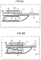
- FIG. 2A shows an example of the arrangement of the arrangement shown in FIG Holding device V shown in a housing of a data carrier evaluation device KL, for example a chip or Magnetic card reader - hereinafter referred to as KL card reader -, shown.
- the card reader KL is for example Part of a public or private card phone - not shown.
- the card reader KL a contacting unit KON for reading out or processing of information stored on a chip or magnetic card CK on, the contacting unit KON being more integral Part of a guide channel arranged in the card reader KL FK for inserting chip or magnetic cards.
- the device V shown in FIG arranged in the housing of the card reader KL or there locked that the spring-loaded locking device SUT together with the two ramp-shaped opening elements R in protrude the guide channel FK, or are arranged there.
- the locking device SUT with the two opening elements R through the Bending element B which is locked on the housing of the card reader KL Holding device V by a arranged in the guide channel FK and correspondingly designed opening OF in the Guide channel FK pressed so that this through the locking device SUT is closed.
- the one at the end of the bent part B arranged stop surface AF is against the outer wall W of the guide channel FK pressed.
- 2A is an example one arranged at an input E of the guide channel FK Chip or magnetic card CK shortly before insertion in the sliding direction sr in the card reader KL or in its Guide channel FK shown.
- the locking device SUT In the closed state of the locking device SUT two wedge-shaped opening elements R each in the edge area of the guide channel FK arranged, the slopes of the opening elements R one from the guide channel direction or from the direction of insertion sr of the chip or magnetic card Have direction.
- the two wedge-shaped opening elements R By inserting a chip or Magnetic card CK in the guide channel FK of the card reader KL, the two wedge-shaped opening elements R through the pushing forces acting on the slopes of the ramps R. down and thus the locking device SUT off the guide channel FK pressed - by a dashed Arrow indicated in FIG 2B.
- the chip or magnetic card CK is so far in the guide channel FK of the card reader KL can be inserted until the contact unit KON of the card reader KL with one or more corresponding Counter-contacting units - not shown - the inserted card CK for bidirectional data exchange connected is.
- the inserted chip card CK can at any time again from the guide channel FK of the card reader KL can be removed or pulled out, with the resilient designed bending part B when pulling out the card CK SUT locking device together with the two opening elements R are pressed back into the guide channel FK and thus the guide channel FK is closed again - cf.
- FIG 2A The chip or magnetic card CK is so far in the guide channel FK of the card reader KL can be inserted until the contact unit KON of the card reader KL with one or more corresponding Counter-contacting units - not shown - the inserted card CK for bidirectional data exchange connected is.
- the inserted chip card CK can at any time again from the guide channel FK of the card reader KL can be
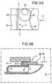
- FIG. 3A shows a top view
- FIG. 3B shows a side view the closed arrangement of the locking device SUT with one inserted into the entrance area E of the guide channel FK, coin-shaped object GM, KM.
- an insertion for example, one with a large diameter Coin GM in the entrance area E of the guide channel 3A with closed locking device SUT the arranged on the side edges of the guide channel FK, wedge-shaped opening elements R - or their slopes - not reached due to the large rounding of the GM coin, whereby the locking device SUT according to the invention not down and therefore not pressed out of the guide channel FK can be.
- the locking device can be advantageous SUT slightly inclined against the insertion direction sr of the guide channel FK, or the CP card be inclined - cf. 3B -, What the locking effect of the locking device SUT further is improved because the inclined locking device SUT by trying to insert or push in one Coin GM, KM in the guide channel FK through on the inclined Locking device SUT rather acting pushing forces pressed more strongly into the guide channel FK, i.e. in the blocking direction becomes.
- FIG. 3A is a cover in the entrance area E of the guide channel FK AB arranged through which the insertion of one small diameter coins KM in the guide channel FK prevents and thus the insertion of smaller ones Coins KM possibly in the area of the slopes of the wedge-shaped Opening elements R and a possible opening or pushing the shooting device SUT away from the guide channel FK is prevented.
Landscapes
- Physics & Mathematics (AREA)
- General Physics & Mathematics (AREA)
- Engineering & Computer Science (AREA)
- Theoretical Computer Science (AREA)
- Control Of Vending Devices And Auxiliary Devices For Vending Devices (AREA)
- Conveying Record Carriers (AREA)
- Testing Of Coins (AREA)
Abstract
Description
Bei aktuellen öffentlichen Kartentelefonen erfolgt die Bezahlung der geführten Telefonate mit Hilfe von Magnet- oder Chip-Karten, deren Wert nach einem geführten Gespräch entsprechend den Telefongebühren reduziert wird. Eine alternative Zahlungsvariante stellt das Auslesen von auf den Magnet- oder Chip-Karten gespeicherten Benutzerdaten dar, wobei nachträglich ein Konto des Benutzers entsprechend belastet wird.Payment is made for current public card phones of the phone calls made using magnetic or Chip cards, the value of which after a conversation telephone charges are reduced. An alternative Payment variant reads out on the magnet or Chip cards represent stored user data, afterwards an account of the user is charged accordingly.
Aktuelle Kartenleser zum Auslesen der auf den Magnet- oder Chip-Karten gespeicherten Informationen sind meist als offene Steckleser gebaut, bei denen die Karte im gesteckten Zustand noch sichtbar bleibt und somit wieder entnehmbar ist. Der Kartenleser weist einen Führungskanal zum Einschieben von Magnet- oder Chip-Karten auf, wobei der Führungskanal derart ausgestaltet ist, daß auch eine Prägung aufweisende Karten einschiebbar sind.Current card reader for reading out on the magnet or Chip card information is mostly considered open Plug-in reader built, in which the card is inserted remains visible and can therefore be removed again. Of the Card reader has a guide channel for inserting magnetic or chip cards, the guide channel being such is designed that also have embossed cards can be inserted.
Aus dem Gebrauchsmuster G 92 13 283.9 geht beispielsweise ein Kartenleser mit einem Führungskanal für tragbare, kartenförmige Datenträger hervor, welcher eine Schließvorrichtung zum Schließen des Führungskanals aufweist. Ein im Ruhezustand den Führungskanal verschließender Schieber weist zwei in den Randbereichen des Führungskanals senkrecht zum Schieber angeordnete, keilförmige Ansätze auf, wobei unterhalb der Ansätze im Schieber eine Öffnung zur Aufnahme der Karte vorgesehen ist. Beim Einbringen einer ordnungsgemäßen Karte gelangt diese zunächst an den beiden keilförmig zum Einführschlitz verlaufende Ansätze zur Anlage, wodurch der Schieber soweit innerhalb seiner Führung verschoben wird, bis die unterhalb der Ansätze vorgesehene Öffnung im Schieber erreicht ist. Durch diese Öffnung kann dann die Karte in das Kartenleserinnere weiter eingebracht werden. Der Schieber ist so ausgestaltet, daß vor dem Einführen der Karte das Einbringen von Fremdgegenständen (z.B. Papier), die zur Unbrauchbarkeit des Kartenleser führen, sowie das Eindringen von Schmutz und Feuchtigkeit in das Kartenleserinnere verhindert wird.The utility model G 92 13 283.9 includes, for example Card reader with a guide channel for portable, card-shaped Data carrier emerges, which a locking device for Has closing the guide channel. One at rest Guide channel closing slide has two in the Edge areas of the guide channel arranged perpendicular to the slide, wedge-shaped approaches, being below the approaches an opening is provided in the slide for receiving the card is. When inserting a proper card arrives these first wedge-shaped on the two to the insertion slot ongoing approaches to the system, whereby the slide so far is moved within its leadership until the below the approaches provided opening in the slide is reached. The card can then enter the card reader through this opening to be introduced further. The slide is designed that before inserting the card Foreign objects (e.g. paper) that make the Lead card readers, as well as the ingress of dirt and Moisture in the inside of the card reader is prevented.
Da der Prägebereich einer Karte beispielsweise eine Breite von ca. 20 mm und die Kartendicke im Prägebereich eine Höhe von über 1,2 mm aufweisen kann, können an dieser Stelle irrtümlich oder auch absichtlich Münzen oder münzförmige Gegenstände in den an die Prägung der Karte angepaßten Kartenschlitz bzw. Führungskanal des Kartenlesers geschoben werden. Dies führt zu einer Verstopfung des Kartenlesers, was den Ausfall der Geräte bzw. Kartentelefone zur Folge hat. Zur Wiederherstellung der Funktionalität des Kartenlesers ist ein Wartungsvorgang erforderlich.For example, because the embossing area of a card is a width of approx. 20 mm and the card thickness in the embossing area a height of over 1.2 mm can be erroneous at this point or intentionally coins or coin-shaped objects in the card slot adapted to the embossing of the card or guide channel of the card reader. This leads to a blockage of the card reader, which the Failure of the devices or card phones. For Restoring the functionality of the card reader is a Maintenance process required.
Um ein absichtliches oder irrtümliches Verstopfen von Kartenlesern durch eingeschobene Münzen zu vermeiden, sind aktuell eingesetzte Kartenleser, sofern der Platz im Gerät ausreichend ist, mit einem ausreichend dimensionierten Innenraum versehen, so daß eingeschobene, münzförmige Gegenstände möglichst beim Einschieben der nächsten Karte in das Geräteinnere geschoben werden und dort bis zum nächsten Wartungsgang liegen bleiben. Die Kartenleser müssen dabei so ausgestaltet sein, daß ins Geräteinnere geschobene, münzförmige Gegenstände beispielsweise keine Kurzschlüsse verursachen.To deliberately or accidentally clog card readers Avoid by inserting coins are current Card reader used, provided there is sufficient space in the device is, with a sufficiently dimensioned interior provided so that inserted, coin-shaped objects as possible when the next card is inserted into the device be pushed and there until the next maintenance cycle to lie down. The card readers must be designed in this way be that coin-shaped objects pushed inside the device for example, do not cause short circuits.
Der Erfindung liegt die Aufgabe zugrunde, das Einschieben von münzförmigen Gegenständen bei Kartenlesern zum Auslesen von Magnet- oder Chip-Karten zu verhindern. Die Aufgabe wird ausgehend von einer Datenträger-Auswertevorrichtung gemäß dem Oberbegriff des Patentanspruchs 1 durch dessen kennzeichnende Merkmale gelöst.The invention has for its object the insertion of coin - shaped objects in card readers for reading out To prevent magnetic or chip cards. The task is starting from a data carrier evaluation device according to the Preamble of claim 1 by its characterizing Features resolved.
Die erfindungsgemäße, einen Führungskanal für tragbare, kartenförmige Datenträger aufweisenden Datenträger-Auswertevorrichtung weist eine federnde Schließvorrichtung zum Schließen des Führungskanals und zumindest ein mit der Schließvorrichtung verbundenes Öffnungselement auf, das im geschlossenen Zustand der Schließvorrichtung in einem Randbereich des Führungskanals angeordnet ist und eine zur Schließvorrichtung in Einschieberichtung ansteigende Auflauffläche aufweist. Desweiteren ist vor dem Öffnungselement eine Führungskanalabdeckung vorgesehen. Die Schließvorrichtung und die Auflauffläche sind derart ausgestaltet, daß bei Einschieben des kartenförmigen Datenträgers die Schließvorrichtung aus dem Führungskanal gedrückt wird. Der wesentliche Aspekt der erfindungsgemäßen Datenträger-Auswertevorrichtung besteht darin, daß das Öffnungselement und die Führungskanalabdeckung derart dimensioniert sind, daß das Öffnungselement nicht von in den Führungskanal eingeschobenen münzförmigen Gegenständen erreicht wird.The inventive, a guide channel for portable, card-shaped Data carrier evaluation device having data carriers has a resilient closing device for closing of the guide channel and at least one with the locking device connected opening element on the closed State of the locking device in an edge region of the guide channel is arranged and one for the locking device in Insertion direction increasing ramp surface. Furthermore, there is a guide channel cover in front of the opening element intended. The locking device and the ramp surface are designed such that when the card-shaped data carrier the locking device from the Guide channel is pressed. The essential aspect of the invention Data carrier evaluation device exists in that the opening element and the guide channel cover are dimensioned such that the opening element is not of coin-shaped objects inserted into the guide channel is achieved.
Der wesentliche Vorteil der erfindungsgemäßen Datenträger-Auswertevorrichtung besteht darin, daß auf einfachste mechanische Weise und damit mit geringstem wirtschaftlichem Aufwand der Einwurf von nicht kartenförmigen Gegenständen - wie beispielsweise münzförmigen Gegenständen - in Vorrichtungen zum Auswerten von Chip- oder Magnet-Karten verhindert wird und somit zusätzliche, mit hohem wirtschaftlichen Aufwand verbundene Wartungsgänge eingespart werden. Durch das Verhindern einer absichtlichen oder irrtümlichen Verstopfung des Kartenlesers bleibt die Funktionalität der Geräte voll erhalten, wodurch Umsatzeinbußen vermieden werden.The main advantage of the data carrier evaluation device according to the invention consists in the simplest mechanical Wise and therefore with the least economic effort the insertion of non-card-shaped objects - like for example coin-shaped objects - in devices for evaluating chip or magnetic cards is prevented and therefore additional, with high economic effort associated maintenance operations can be saved. By the Prevent deliberate or accidental constipation the functionality of the devices remains full received, thereby avoiding sales losses.
Weitere vorteilhafte Ausgestaltungen der erfindungsgemäßen Datenträger-Auswertevorrichtung sind den weiteren Ansprüchen zu entnehmen.Further advantageous embodiments of the invention Data carrier evaluation device are the further claims refer to.
Im folgenden wird ein Ausführungsbeispiel der erfindungsgemäßen Datenträger-Auswertevorrichtung mit Hilfe von drei Zeichnungen näher erläutert. Dabei zeigen:
- FIG 1
- eine Haltevorrichtung mit federnder Schließvorrichtung zur Verhinderung des Einführens münzförmiger Gegenstände,
- FIG 2A und FIG 2B
- die in einen Führungskanal einer Datenträger-Auswertevorrichtung angeordnete Schließvorrichtung im geschlossenem Zustand und die aus dem Führungskanal gedrückte Schließvorrichtung bei einem in den Führungskanal eingeschobenen, kartenförmigen Datenträger,
- FIG 3A und FIG 3B
- eine Darstellung der Schließwirkung der im Führungskanal der Datenträger-Auswertevorrichtung angeordneten Schließvorrichtung bei einem in den Führungskanal eingeschobenen, münzförmigen Gegenstand.
- FIG. 1
- a holding device with a resilient closing device to prevent the insertion of coin-shaped objects,
- FIG 2A and FIG 2B
- the locking device arranged in a guide channel of a data carrier evaluation device in the closed state and the locking device pressed out of the guide channel in the case of a card-shaped data carrier inserted into the guide channel,
- FIG. 3A and FIG. 3B
- a representation of the closing effect of the locking device arranged in the guide channel of the data carrier evaluation device in the case of a coin-shaped object inserted into the guide channel.
In FIG 1 ist eine Haltevorrichtung V mit angeordneter Schließvorrichtung SUT zur Verhinderung des Einführens von münzförmigen Gegenständen in einen Führungskanal einer Datenträger-Auswertevorrichtung - in FIG 1 nicht abgebildet - skizzenhaft dargestellt. Auf einer Grundplatte G ist ein annähernd U-förmiges Biegeelement bzw. Biegeteil B befestigt, wobei am federnd gelagerten Ende des Biegeteils B eine federnde, als annähernd schräg über das Biegeteil B verlaufende Verschluß-Fläche ausgestaltete Schließvorrichtung SUT - auch als Shutter bezeichnet - angebracht ist. An den seitlichen Rändern der Schließvorrichtung SUT ist jeweils ein annähernd im rechten Winkel zur Schließvorrichtung SUT angeordnetes und jeweils eine Schräge aufweisendes Öffnungselement R - im folgenden auch als Rampe bezeichnet - angebracht, wobei die beiden Öffnungselemente R bezüglich der Einschieberichtung des Führungskanals vor der Schließvorrichtung SUT an den Seitenrändern des U-förmigen Biegeelementes B angeordnet sind. Gemäß FIG 1 sind die Schließvorrichtung SUT und die beiden rampenförmigen, bzw. keilförmigen Öffnungselemente R derart am federnd gelagerten Ende des Biegeteils B angeordnet, daß durch die genannten Elemente SUT, R, B eine Anschlagfläche AF gebildet wird.In Figure 1, a holding device V is arranged SUT locking device to prevent the insertion of coin-shaped objects in a guide channel of a data carrier evaluation device - not shown in FIG. 1 - shown sketchy. On a base plate G is approximately U-shaped bending element or bent part B attached, a resilient, at the resiliently mounted end of the bent part B as running approximately obliquely over the bent part B. Locking surface designed locking device SUT - too referred to as shutter - is appropriate. On the side The edges of the locking device SUT are approximate arranged at right angles to the locking device SUT and each have an inclined opening element R - in the following also referred to as a ramp - attached, the two Opening elements R with respect to the direction of insertion Guide channel in front of the SUT locking device on the side edges of the U-shaped bending element B are arranged. According to 1 shows the locking device SUT and the two ramp-shaped, or wedge-shaped opening elements R in such a way resilient end of the bent part B arranged that by the elements SUT, R, B mentioned a stop surface AF is formed.
In FIG 2A ist ein Beispiel für die Anordnung der in FIG 1 dargestellten Haltevorrichtung V in einem Gehäuse einer Datenträger-Auswertevorrichtung KL, beispielsweise einem Chip- bzw. Magnetkartenleser - im folgenden als Kartenleser KL bezeichnet -, dargestellt. Der Kartenleser KL ist beispielsweise Bestandteil eines öffentlichen oder privaten Kartentelefons - nicht dargestellt. Gemäß FIG 2A weist der Kartenleser KL eine Kontaktiereinheit KON zum Auslesen oder Bearbeiten von auf einer Chip- oder Magnetkarte CK gespeicherten Informationen auf, wobei die Kontaktiereinheit KON integraler Bestandteil eines im Kartenleser KL angeordneten Führungskanals FK zum Einführen von Chip- oder Magnetkarten ist. Erfindungsgemaß ist die in FIG 1 dargestellte Vorrichtung V derart im Gehäuse des Kartenlesers KL angeordnet bzw. dort arretiert, daß die federnd gelagerte Schließvorrichtung SUT zusammen mit den beiden rampenförmigen Öffnungselementen R in den Führungskanal FK ragen, bzw. dort angeordnet sind. Im unbenutztem Zustand des Kartenlesers KL werden die Schließvorrichtung SUT mit den beiden Öffnungslementen R durch das Biegeelement B der am Gehäuse des Kartenlesers KL arretierten Haltevorrichtung V durch eine im Führungskanal FK angeordnete und entsprechend ausgestaltete Öffnung OF in den Führungskanal FK gedrückt, so daß dieser durch die Schließvorrichtung SUT verschlossen ist. Die am Ende des Biegeteils B angeordnete Anschlagfläche AF wird dabei gegen die Außenwand W des Führungskanals FK gedrückt. In FIG 2A ist beispielhaft eine an einem Eingang E des Führungskanals FK angeordnete Chip- bzw. Magnetkarte CK kurz vor den Einschieben in Schieberichtung sr in den Kartenleser KL bzw. in dessen Führungskanal FK dargestellt.FIG. 2A shows an example of the arrangement of the arrangement shown in FIG Holding device V shown in a housing of a data carrier evaluation device KL, for example a chip or Magnetic card reader - hereinafter referred to as KL card reader -, shown. The card reader KL is for example Part of a public or private card phone - not shown. According to FIG 2A, the card reader KL a contacting unit KON for reading out or processing of information stored on a chip or magnetic card CK on, the contacting unit KON being more integral Part of a guide channel arranged in the card reader KL FK for inserting chip or magnetic cards. According to the invention is the device V shown in FIG arranged in the housing of the card reader KL or there locked that the spring-loaded locking device SUT together with the two ramp-shaped opening elements R in protrude the guide channel FK, or are arranged there. in the unused condition of the card reader KL are the locking device SUT with the two opening elements R through the Bending element B which is locked on the housing of the card reader KL Holding device V by a arranged in the guide channel FK and correspondingly designed opening OF in the Guide channel FK pressed so that this through the locking device SUT is closed. The one at the end of the bent part B arranged stop surface AF is against the outer wall W of the guide channel FK pressed. 2A is an example one arranged at an input E of the guide channel FK Chip or magnetic card CK shortly before insertion in the sliding direction sr in the card reader KL or in its Guide channel FK shown.
Im geschlossenen Zustand der Schließvorrichtung SUT sind die beiden keilförmigen Öffnungselemente R jeweils im Randbereich des Führungskanals FK angeordnet, wobei die Schrägen der Öffnungselemente R eine von der Führungskanalrichtung bzw. von der Einschieberichtung sr der Chip- bzw. Magentkarte abweichende Richtung aufweisen. Durch das Einschieben einer Chip- bzw. Magnetkarte CK in den Führungskanal FK des Kartenlesers KL werden die beiden keilförmigen Öffnungselemente R durch die jeweils auf die Schrägen der Rampen R einwirkenden Schiebekräfte nach unten und somit die Schließvorrichtung SUT aus dem Führungskanal FK gedrückt - durch einen strichlierten Pfeil in FIG 2B angedeutet.In the closed state of the locking device SUT two wedge-shaped opening elements R each in the edge area of the guide channel FK arranged, the slopes of the opening elements R one from the guide channel direction or from the direction of insertion sr of the chip or magnetic card Have direction. By inserting a chip or Magnetic card CK in the guide channel FK of the card reader KL, the two wedge-shaped opening elements R through the pushing forces acting on the slopes of the ramps R. down and thus the locking device SUT off the guide channel FK pressed - by a dashed Arrow indicated in FIG 2B.
Die Chip- bzw. Magentkarte CK ist soweit in den Führungskanal FK des Kartenlesers KL einschiebbar, bis die Kontaktiereinheit KON des Kartenlesers KL mit einer oder mehreren entsprechenden Gegen-Kontaktiereinheiten - nicht dargestellt - der eingeschobenen Karte CK zwecks bidirektionalen Datenaustausch verbunden ist. Die eingeschobene Chipkarte CK kann jederzeit wieder aus dem Führungskanal FK des Kartenlesers KL entnommen bzw. herausgezogen werden, wobei durch das federnd ausgestaltete Biegeteil B bei Herausziehen der Karte CK die Schließvorrichtung SUT zusammen mit den beiden Öffnungselementen R wieder in den Führungskanal FK gedrückt werden und somit der Führungskanal FK wieder verschlossen ist - vgl. FIG 2A.The chip or magnetic card CK is so far in the guide channel FK of the card reader KL can be inserted until the contact unit KON of the card reader KL with one or more corresponding Counter-contacting units - not shown - the inserted card CK for bidirectional data exchange connected is. The inserted chip card CK can at any time again from the guide channel FK of the card reader KL can be removed or pulled out, with the resilient designed bending part B when pulling out the card CK SUT locking device together with the two opening elements R are pressed back into the guide channel FK and thus the guide channel FK is closed again - cf. FIG 2A.
FIG 3A zeigt in einer Draufsicht und FIG 3B in einer Seitenansicht die geschlossene Anordnung der Schließvorrichtung SUT bei einem in den Eingangsbereich E des Führungskanals FK eingeschobenen, münzförmigen Gegenstand GM, KM. Bei einem Einschieben beispielsweise einer einen großen Durchmesser aufweisenden Münze GM in den Eingangsbereich E des Führungskanals FK werden gemäß FIG 3A bei geschlossener Schließvorrichtung SUT die an den Seitenrändern des Führungskanals FK angeordneten, keilförmigen Öffnungselemente R - bzw. deren Schrägen - bedingt durch die große Rundung der Münze GM nicht erreicht, wodurch die Schließvorrichtung SUT erfindungsgemäß nicht nach unten und somit nicht aus dem Führungskanal FK gedrückt werden kann. Vorteilhaft kann die Schließvorrichtung SUT leicht schräg gegen die Einschieberichtung sr des Führungskanals FK, bzw. der Karte CP geneigt sein - vgl. FIG 3B -, wodurch die Sperrwirkung der Schließvorrichtung SUT weiter verbessert wird, da die schräg angeordnete Schließvorrichtung SUT durch den Versuch des Einschiebens bzw. Eindrückens einer Münze GM, KM in den Führungskanal FK durch auf die schräg geneigte Schließvorrichtung SUT einwirkende Schiebekräfte eher stärker in den Führungskanal FK, also in Sperrichtung gedrückt wird.FIG. 3A shows a top view and FIG. 3B shows a side view the closed arrangement of the locking device SUT with one inserted into the entrance area E of the guide channel FK, coin-shaped object GM, KM. With an insertion for example, one with a large diameter Coin GM in the entrance area E of the guide channel 3A with closed locking device SUT the arranged on the side edges of the guide channel FK, wedge-shaped opening elements R - or their slopes - not reached due to the large rounding of the GM coin, whereby the locking device SUT according to the invention not down and therefore not pressed out of the guide channel FK can be. The locking device can be advantageous SUT slightly inclined against the insertion direction sr of the guide channel FK, or the CP card be inclined - cf. 3B -, What the locking effect of the locking device SUT further is improved because the inclined locking device SUT by trying to insert or push in one Coin GM, KM in the guide channel FK through on the inclined Locking device SUT rather acting pushing forces pressed more strongly into the guide channel FK, i.e. in the blocking direction becomes.
Gemäß einer in FIG 3A dargestellten, vorteilhaften Ausgestaltung ist im Eingangsbereich E des Führungskanals FK eine Abdeckung AB angeordnet, durch welche das Einschieben von einen kleinen Durchmesser aufweisenden Münzen KM in den Führungskanal FK verhindert und somit ein Einschieben von kleineren Münzen KM eventuell in den Bereich der Schrägen der keilförmigen Öffnungselemente R und ein dadurch mögliches Öffnen bzw. Wegdrücken der Schießvorrichtung SUT aus dem Führungskanal FK unterbunden wird.According to an advantageous embodiment shown in FIG. 3A is a cover in the entrance area E of the guide channel FK AB arranged through which the insertion of one small diameter coins KM in the guide channel FK prevents and thus the insertion of smaller ones Coins KM possibly in the area of the slopes of the wedge-shaped Opening elements R and a possible opening or pushing the shooting device SUT away from the guide channel FK is prevented.
Claims (4)
mit einer federnden Schließvorrichtung (SUT) zum Schließen des Führungskanals (FK),
mit zumindest einem mit der Schließvorrichtung (SUT) verbundenen Öffnungselement (R), das im geschlossenen Zustand der Schließvorrichtung (SUT) in einem Randbereich des Führungskanals (FK) angeordnet ist und eine zur Schließvorrichtung (SUT) in Einschieberichtung (sr) ansteigende Auflauffläche aufweist,
mit einer vor dem Öffnungselement (R) vorgesehenen Führungskanalabdeckung (AB),
wobei die Schließvorrichtung (SUT) und die Auflauffläche des Öffnungselementes (R) derart ausgestaltet sind, daß bei Einschieben des kartenförmigen Datenträgers (CK) die Schließvorrichtung (SUT) aus dem Führungskanal (FK) gedrückt wird,
dadurch gekennzeichnet,
daß das Öffnungselement (R) und die Führungskanalabdeckung (AB) derart dimensioniert sind, daß das Öffnungselement (R) nicht von in den Führungskanal (FK) eingeschobenen münzförmigen Gegenständen (GM,KM) erreicht wird.Data carrier evaluation device (KL), with a guide channel (FK) for portable, card-shaped data carriers,
with a resilient closing device (SUT) for closing the guide channel (FK),
with at least one opening element (R) connected to the closing device (SUT), which in the closed state of the closing device (SUT) is arranged in an edge region of the guide channel (FK) and has a ramp surface rising towards the closing device (SUT) in the insertion direction (sr),
with a guide channel cover (AB) provided in front of the opening element (R),
wherein the closing device (SUT) and the run-up surface of the opening element (R) are designed such that when the card-shaped data carrier (CK) is inserted, the closing device (SUT) is pressed out of the guide channel (FK),
characterized by
that the opening element (R) and the guide channel cover (AB) are dimensioned such that the opening element (R) is not reached by coin-shaped objects (GM, KM) inserted into the guide channel (FK).
daß die Abdeckung (AB) in dem von dem Öffnungselement (R) abgewandten Randbereich eine bogenförmige Aussparung aufweist.Data carrier evaluation device according to claim 1, characterized in that
that the cover (AB) has an arcuate recess in the edge region facing away from the opening element (R).
dadurch gekennzeichnet,
daß die Schließvorrichtung (SUT) im geschlossenen Zustand eine gegen die Einschieberichtung (sr) gerichtete Neigung aufweist. Data carrier evaluation device according to one of the preceding claims,
characterized by
that the closing device (SUT) in the closed state has an inclination directed against the direction of insertion (sr).
dadurch gekennzeichnet,
daß die Datenträger-Auswertevorrichtung (KL) in einem öffentlichen oder privaten Karten-Telefon angeordnet ist.Data carrier evaluation device according to one of the preceding claims,
characterized by
that the data carrier evaluation device (KL) is arranged in a public or private card telephone.
Applications Claiming Priority (2)
| Application Number | Priority Date | Filing Date | Title |
|---|---|---|---|
| DE19824815 | 1998-06-03 | ||
| DE1998124815 DE19824815A1 (en) | 1998-06-03 | 1998-06-03 | Data carrier evaluation device with a guide channel for portable, card-shaped data carriers |
Publications (2)
| Publication Number | Publication Date |
|---|---|
| EP0962879A2 true EP0962879A2 (en) | 1999-12-08 |
| EP0962879A3 EP0962879A3 (en) | 2002-01-16 |
Family
ID=7869789
Family Applications (1)
| Application Number | Title | Priority Date | Filing Date |
|---|---|---|---|
| EP99110574A Withdrawn EP0962879A3 (en) | 1998-06-03 | 1999-06-01 | Device for evaluating portable, card-shaped data carriers with a guiding channel |
Country Status (2)
| Country | Link |
|---|---|
| EP (1) | EP0962879A3 (en) |
| DE (1) | DE19824815A1 (en) |
Cited By (2)
| Publication number | Priority date | Publication date | Assignee | Title |
|---|---|---|---|---|
| FR2837958A1 (en) * | 2002-03-27 | 2003-10-03 | Amphenol Tuchel Elect | Card reader for a chip or memory card, has a connector with a shutter to prevent dirt ingress, said shutter being operated by a torsion return spring |
| EP1975853A1 (en) | 2007-03-30 | 2008-10-01 | AMPHENOL-TUCHEL ELECTRONICS GmbH | Device for reading and/or writing cards |
Family Cites Families (3)
| Publication number | Priority date | Publication date | Assignee | Title |
|---|---|---|---|---|
| DE4139482A1 (en) * | 1991-11-29 | 1993-06-03 | Man Technologie Gmbh | Mechanical protection system for electronic card readers - has mechanical flap held in closed position that can once be displaced by card insertion |
| DE9213283U1 (en) * | 1992-10-02 | 1992-11-26 | Siemens AG, 8000 München | Card reader |
| DE19547060C2 (en) * | 1995-12-18 | 1998-05-14 | Bernhard Vogler | Device for closing and / or locking the card insertion slot on code card readers |
-
1998
- 1998-06-03 DE DE1998124815 patent/DE19824815A1/en not_active Withdrawn
-
1999
- 1999-06-01 EP EP99110574A patent/EP0962879A3/en not_active Withdrawn
Cited By (2)
| Publication number | Priority date | Publication date | Assignee | Title |
|---|---|---|---|---|
| FR2837958A1 (en) * | 2002-03-27 | 2003-10-03 | Amphenol Tuchel Elect | Card reader for a chip or memory card, has a connector with a shutter to prevent dirt ingress, said shutter being operated by a torsion return spring |
| EP1975853A1 (en) | 2007-03-30 | 2008-10-01 | AMPHENOL-TUCHEL ELECTRONICS GmbH | Device for reading and/or writing cards |
Also Published As
| Publication number | Publication date |
|---|---|
| EP0962879A3 (en) | 2002-01-16 |
| DE19824815A1 (en) | 1999-12-09 |
Similar Documents
| Publication | Publication Date | Title |
|---|---|---|
| DE10021396B4 (en) | Contacting device for a chip card, in particular a SIM card | |
| DE19521721B4 (en) | Shielded contacting device | |
| DE69418810T2 (en) | Portable multi-purpose card for personal computers | |
| DE19806844C2 (en) | Portable telephone device | |
| EP0775964B1 (en) | Contact unit for card-shaped carriers with electronic components | |
| DE60220480T2 (en) | Card connector device for various card types | |
| DE69834302T2 (en) | Chip card connector | |
| DE60025936T2 (en) | SWITCHING DEVICE FOR CARD CONNECTORS | |
| DE69420442T2 (en) | Portable telephone combined with a card | |
| DE10038287A1 (en) | Plug-in card for electronic devices | |
| DE3343727A1 (en) | Card reader for cash registers | |
| DE69625407T2 (en) | SIM card connector | |
| DE602004013036T2 (en) | MEMORY CARD CONNECTOR WITH CARD EXCHANGE MECHANISM | |
| DE10245483A1 (en) | Memory card adapter has tray with conductive base and through holes and cover which can be pushed open or shut | |
| EP1008280A1 (en) | Contacting unit for a card-shaped carrying element of electronic modules, especially according to pcmcia standards | |
| DE60126201T2 (en) | Electrical card connector | |
| DE9012889U1 (en) | Card reader for electrical communications | |
| EP0894310B1 (en) | Card reading device | |
| EP0731415B1 (en) | Case for a chipcard | |
| EP0924867A2 (en) | Card reader for mobile transceivers | |
| DE3020728A1 (en) | VALUE CARD TELEPHONE | |
| EP0962879A2 (en) | Device for evaluating portable, card-shaped data carriers with a guiding channel | |
| DE69602731T2 (en) | CARD CONNECTOR ARRANGEMENT | |
| DE60319356T2 (en) | MEMORY CARD CONNECTOR WITH FUSE FOR INCORRECT CARD INTRODUCTION | |
| DE69803549T2 (en) | CARD READER CONNECTION |
Legal Events
| Date | Code | Title | Description |
|---|---|---|---|
| PUAI | Public reference made under article 153(3) epc to a published international application that has entered the european phase |
Free format text: ORIGINAL CODE: 0009012 |
|
| AK | Designated contracting states |
Kind code of ref document: A2 Designated state(s): AT BE CH CY DE DK ES FI FR GB GR IE IT LI LU MC NL PT SE |
|
| AX | Request for extension of the european patent |
Free format text: AL;LT;LV;MK;RO;SI |
|
| PUAL | Search report despatched |
Free format text: ORIGINAL CODE: 0009013 |
|
| AK | Designated contracting states |
Kind code of ref document: A3 Designated state(s): AT BE CH CY DE DK ES FI FR GB GR IE IT LI LU MC NL PT SE |
|
| AX | Request for extension of the european patent |
Free format text: AL;LT;LV;MK;RO;SI |
|
| RIC1 | Information provided on ipc code assigned before grant |
Free format text: 7G 06K 13/08 A, 7G 06K 7/00 B |
|
| AKX | Designation fees paid | ||
| REG | Reference to a national code |
Ref country code: DE Ref legal event code: 8566 |
|
| STAA | Information on the status of an ep patent application or granted ep patent |
Free format text: STATUS: THE APPLICATION IS DEEMED TO BE WITHDRAWN |
|
| 18D | Application deemed to be withdrawn |
Effective date: 20020717 |