EP0962391B9 - A method of applying fitments to containers and apparatus for use in the same - Google Patents
A method of applying fitments to containers and apparatus for use in the same Download PDFInfo
- Publication number
- EP0962391B9 EP0962391B9 EP99116441A EP99116441A EP0962391B9 EP 0962391 B9 EP0962391 B9 EP 0962391B9 EP 99116441 A EP99116441 A EP 99116441A EP 99116441 A EP99116441 A EP 99116441A EP 0962391 B9 EP0962391 B9 EP 0962391B9
- Authority
- EP
- European Patent Office
- Prior art keywords
- fitment
- applicator
- placing
- receiving means
- fixing
- Prior art date
- Legal status (The legal status is an assumption and is not a legal conclusion. Google has not performed a legal analysis and makes no representation as to the accuracy of the status listed.)
- Revoked
Links
Images


Classifications
-
- B—PERFORMING OPERATIONS; TRANSPORTING
- B29—WORKING OF PLASTICS; WORKING OF SUBSTANCES IN A PLASTIC STATE IN GENERAL
- B29C—SHAPING OR JOINING OF PLASTICS; SHAPING OF MATERIAL IN A PLASTIC STATE, NOT OTHERWISE PROVIDED FOR; AFTER-TREATMENT OF THE SHAPED PRODUCTS, e.g. REPAIRING
- B29C66/00—General aspects of processes or apparatus for joining preformed parts
- B29C66/50—General aspects of joining tubular articles; General aspects of joining long products, i.e. bars or profiled elements; General aspects of joining single elements to tubular articles, hollow articles or bars; General aspects of joining several hollow-preforms to form hollow or tubular articles
- B29C66/51—Joining tubular articles, profiled elements or bars; Joining single elements to tubular articles, hollow articles or bars; Joining several hollow-preforms to form hollow or tubular articles
- B29C66/53—Joining single elements to tubular articles, hollow articles or bars
- B29C66/532—Joining single elements to the wall of tubular articles, hollow articles or bars
- B29C66/5324—Joining single elements to the wall of tubular articles, hollow articles or bars said single elements being substantially annular, i.e. of finite length
- B29C66/53245—Joining single elements to the wall of tubular articles, hollow articles or bars said single elements being substantially annular, i.e. of finite length said articles being hollow
- B29C66/53246—Joining single elements to the wall of tubular articles, hollow articles or bars said single elements being substantially annular, i.e. of finite length said articles being hollow said single elements being spouts, e.g. joining spouts to containers
- B29C66/53247—Joining single elements to the wall of tubular articles, hollow articles or bars said single elements being substantially annular, i.e. of finite length said articles being hollow said single elements being spouts, e.g. joining spouts to containers said spouts comprising flanges
-
- B—PERFORMING OPERATIONS; TRANSPORTING
- B29—WORKING OF PLASTICS; WORKING OF SUBSTANCES IN A PLASTIC STATE IN GENERAL
- B29C—SHAPING OR JOINING OF PLASTICS; SHAPING OF MATERIAL IN A PLASTIC STATE, NOT OTHERWISE PROVIDED FOR; AFTER-TREATMENT OF THE SHAPED PRODUCTS, e.g. REPAIRING
- B29C65/00—Joining or sealing of preformed parts, e.g. welding of plastics materials; Apparatus therefor
- B29C65/02—Joining or sealing of preformed parts, e.g. welding of plastics materials; Apparatus therefor by heating, with or without pressure
- B29C65/08—Joining or sealing of preformed parts, e.g. welding of plastics materials; Apparatus therefor by heating, with or without pressure using ultrasonic vibrations
-
- B—PERFORMING OPERATIONS; TRANSPORTING
- B29—WORKING OF PLASTICS; WORKING OF SUBSTANCES IN A PLASTIC STATE IN GENERAL
- B29C—SHAPING OR JOINING OF PLASTICS; SHAPING OF MATERIAL IN A PLASTIC STATE, NOT OTHERWISE PROVIDED FOR; AFTER-TREATMENT OF THE SHAPED PRODUCTS, e.g. REPAIRING
- B29C65/00—Joining or sealing of preformed parts, e.g. welding of plastics materials; Apparatus therefor
- B29C65/78—Means for handling the parts to be joined, e.g. for making containers or hollow articles, e.g. means for handling sheets, plates, web-like materials, tubular articles, hollow articles or elements to be joined therewith; Means for discharging the joined articles from the joining apparatus
- B29C65/7802—Positioning the parts to be joined, e.g. aligning, indexing or centring
- B29C65/7838—Positioning the parts to be joined, e.g. aligning, indexing or centring from the inside, e.g. of tubular or hollow articles
-
- B—PERFORMING OPERATIONS; TRANSPORTING
- B29—WORKING OF PLASTICS; WORKING OF SUBSTANCES IN A PLASTIC STATE IN GENERAL
- B29C—SHAPING OR JOINING OF PLASTICS; SHAPING OF MATERIAL IN A PLASTIC STATE, NOT OTHERWISE PROVIDED FOR; AFTER-TREATMENT OF THE SHAPED PRODUCTS, e.g. REPAIRING
- B29C65/00—Joining or sealing of preformed parts, e.g. welding of plastics materials; Apparatus therefor
- B29C65/78—Means for handling the parts to be joined, e.g. for making containers or hollow articles, e.g. means for handling sheets, plates, web-like materials, tubular articles, hollow articles or elements to be joined therewith; Means for discharging the joined articles from the joining apparatus
- B29C65/7841—Holding or clamping means for handling purposes
-
- B—PERFORMING OPERATIONS; TRANSPORTING
- B29—WORKING OF PLASTICS; WORKING OF SUBSTANCES IN A PLASTIC STATE IN GENERAL
- B29C—SHAPING OR JOINING OF PLASTICS; SHAPING OF MATERIAL IN A PLASTIC STATE, NOT OTHERWISE PROVIDED FOR; AFTER-TREATMENT OF THE SHAPED PRODUCTS, e.g. REPAIRING
- B29C65/00—Joining or sealing of preformed parts, e.g. welding of plastics materials; Apparatus therefor
- B29C65/78—Means for handling the parts to be joined, e.g. for making containers or hollow articles, e.g. means for handling sheets, plates, web-like materials, tubular articles, hollow articles or elements to be joined therewith; Means for discharging the joined articles from the joining apparatus
- B29C65/7858—Means for handling the parts to be joined, e.g. for making containers or hollow articles, e.g. means for handling sheets, plates, web-like materials, tubular articles, hollow articles or elements to be joined therewith; Means for discharging the joined articles from the joining apparatus characterised by the feeding movement of the parts to be joined
- B29C65/7879—Means for handling the parts to be joined, e.g. for making containers or hollow articles, e.g. means for handling sheets, plates, web-like materials, tubular articles, hollow articles or elements to be joined therewith; Means for discharging the joined articles from the joining apparatus characterised by the feeding movement of the parts to be joined said parts to be joined moving in a closed path, e.g. a rectangular path
- B29C65/7882—Means for handling the parts to be joined, e.g. for making containers or hollow articles, e.g. means for handling sheets, plates, web-like materials, tubular articles, hollow articles or elements to be joined therewith; Means for discharging the joined articles from the joining apparatus characterised by the feeding movement of the parts to be joined said parts to be joined moving in a closed path, e.g. a rectangular path said parts to be joined moving in a circular path
-
- B—PERFORMING OPERATIONS; TRANSPORTING
- B29—WORKING OF PLASTICS; WORKING OF SUBSTANCES IN A PLASTIC STATE IN GENERAL
- B29C—SHAPING OR JOINING OF PLASTICS; SHAPING OF MATERIAL IN A PLASTIC STATE, NOT OTHERWISE PROVIDED FOR; AFTER-TREATMENT OF THE SHAPED PRODUCTS, e.g. REPAIRING
- B29C66/00—General aspects of processes or apparatus for joining preformed parts
- B29C66/01—General aspects dealing with the joint area or with the area to be joined
- B29C66/05—Particular design of joint configurations
- B29C66/10—Particular design of joint configurations particular design of the joint cross-sections
- B29C66/11—Joint cross-sections comprising a single joint-segment, i.e. one of the parts to be joined comprising a single joint-segment in the joint cross-section
- B29C66/112—Single lapped joints
-
- B—PERFORMING OPERATIONS; TRANSPORTING
- B29—WORKING OF PLASTICS; WORKING OF SUBSTANCES IN A PLASTIC STATE IN GENERAL
- B29C—SHAPING OR JOINING OF PLASTICS; SHAPING OF MATERIAL IN A PLASTIC STATE, NOT OTHERWISE PROVIDED FOR; AFTER-TREATMENT OF THE SHAPED PRODUCTS, e.g. REPAIRING
- B29C66/00—General aspects of processes or apparatus for joining preformed parts
- B29C66/01—General aspects dealing with the joint area or with the area to be joined
- B29C66/05—Particular design of joint configurations
- B29C66/10—Particular design of joint configurations particular design of the joint cross-sections
- B29C66/13—Single flanged joints; Fin-type joints; Single hem joints; Edge joints; Interpenetrating fingered joints; Other specific particular designs of joint cross-sections not provided for in groups B29C66/11 - B29C66/12
- B29C66/131—Single flanged joints, i.e. one of the parts to be joined being rigid and flanged in the joint area
-
- B—PERFORMING OPERATIONS; TRANSPORTING
- B29—WORKING OF PLASTICS; WORKING OF SUBSTANCES IN A PLASTIC STATE IN GENERAL
- B29C—SHAPING OR JOINING OF PLASTICS; SHAPING OF MATERIAL IN A PLASTIC STATE, NOT OTHERWISE PROVIDED FOR; AFTER-TREATMENT OF THE SHAPED PRODUCTS, e.g. REPAIRING
- B29C66/00—General aspects of processes or apparatus for joining preformed parts
- B29C66/50—General aspects of joining tubular articles; General aspects of joining long products, i.e. bars or profiled elements; General aspects of joining single elements to tubular articles, hollow articles or bars; General aspects of joining several hollow-preforms to form hollow or tubular articles
- B29C66/61—Joining from or joining on the inside
-
- B—PERFORMING OPERATIONS; TRANSPORTING
- B29—WORKING OF PLASTICS; WORKING OF SUBSTANCES IN A PLASTIC STATE IN GENERAL
- B29C—SHAPING OR JOINING OF PLASTICS; SHAPING OF MATERIAL IN A PLASTIC STATE, NOT OTHERWISE PROVIDED FOR; AFTER-TREATMENT OF THE SHAPED PRODUCTS, e.g. REPAIRING
- B29C66/00—General aspects of processes or apparatus for joining preformed parts
- B29C66/50—General aspects of joining tubular articles; General aspects of joining long products, i.e. bars or profiled elements; General aspects of joining single elements to tubular articles, hollow articles or bars; General aspects of joining several hollow-preforms to form hollow or tubular articles
- B29C66/63—Internally supporting the article during joining
-
- B—PERFORMING OPERATIONS; TRANSPORTING
- B29—WORKING OF PLASTICS; WORKING OF SUBSTANCES IN A PLASTIC STATE IN GENERAL
- B29C—SHAPING OR JOINING OF PLASTICS; SHAPING OF MATERIAL IN A PLASTIC STATE, NOT OTHERWISE PROVIDED FOR; AFTER-TREATMENT OF THE SHAPED PRODUCTS, e.g. REPAIRING
- B29C66/00—General aspects of processes or apparatus for joining preformed parts
- B29C66/70—General aspects of processes or apparatus for joining preformed parts characterised by the composition, physical properties or the structure of the material of the parts to be joined; Joining with non-plastics material
- B29C66/72—General aspects of processes or apparatus for joining preformed parts characterised by the composition, physical properties or the structure of the material of the parts to be joined; Joining with non-plastics material characterised by the structure of the material of the parts to be joined
- B29C66/723—General aspects of processes or apparatus for joining preformed parts characterised by the composition, physical properties or the structure of the material of the parts to be joined; Joining with non-plastics material characterised by the structure of the material of the parts to be joined being multi-layered
- B29C66/7232—General aspects of processes or apparatus for joining preformed parts characterised by the composition, physical properties or the structure of the material of the parts to be joined; Joining with non-plastics material characterised by the structure of the material of the parts to be joined being multi-layered comprising a non-plastics layer
- B29C66/72327—General aspects of processes or apparatus for joining preformed parts characterised by the composition, physical properties or the structure of the material of the parts to be joined; Joining with non-plastics material characterised by the structure of the material of the parts to be joined being multi-layered comprising a non-plastics layer consisting of natural products or their composites, not provided for in B29C66/72321 - B29C66/72324
- B29C66/72328—Paper
-
- B—PERFORMING OPERATIONS; TRANSPORTING
- B29—WORKING OF PLASTICS; WORKING OF SUBSTANCES IN A PLASTIC STATE IN GENERAL
- B29C—SHAPING OR JOINING OF PLASTICS; SHAPING OF MATERIAL IN A PLASTIC STATE, NOT OTHERWISE PROVIDED FOR; AFTER-TREATMENT OF THE SHAPED PRODUCTS, e.g. REPAIRING
- B29C66/00—General aspects of processes or apparatus for joining preformed parts
- B29C66/80—General aspects of machine operations or constructions and parts thereof
- B29C66/82—Pressure application arrangements, e.g. transmission or actuating mechanisms for joining tools or clamps
- B29C66/824—Actuating mechanisms
- B29C66/8242—Pneumatic or hydraulic drives
-
- B—PERFORMING OPERATIONS; TRANSPORTING
- B29—WORKING OF PLASTICS; WORKING OF SUBSTANCES IN A PLASTIC STATE IN GENERAL
- B29C—SHAPING OR JOINING OF PLASTICS; SHAPING OF MATERIAL IN A PLASTIC STATE, NOT OTHERWISE PROVIDED FOR; AFTER-TREATMENT OF THE SHAPED PRODUCTS, e.g. REPAIRING
- B29C66/00—General aspects of processes or apparatus for joining preformed parts
- B29C66/80—General aspects of machine operations or constructions and parts thereof
- B29C66/83—General aspects of machine operations or constructions and parts thereof characterised by the movement of the joining or pressing tools
- B29C66/832—Reciprocating joining or pressing tools
- B29C66/8322—Joining or pressing tools reciprocating along one axis
-
- B—PERFORMING OPERATIONS; TRANSPORTING
- B31—MAKING ARTICLES OF PAPER, CARDBOARD OR MATERIAL WORKED IN A MANNER ANALOGOUS TO PAPER; WORKING PAPER, CARDBOARD OR MATERIAL WORKED IN A MANNER ANALOGOUS TO PAPER
- B31B—MAKING CONTAINERS OF PAPER, CARDBOARD OR MATERIAL WORKED IN A MANNER ANALOGOUS TO PAPER
- B31B50/00—Making rigid or semi-rigid containers, e.g. boxes or cartons
- B31B50/74—Auxiliary operations
- B31B50/81—Forming or attaching accessories, e.g. opening devices, closures or tear strings
- B31B50/84—Forming or attaching means for filling or dispensing contents, e.g. valves or spouts
-
- B—PERFORMING OPERATIONS; TRANSPORTING
- B65—CONVEYING; PACKING; STORING; HANDLING THIN OR FILAMENTARY MATERIAL
- B65B—MACHINES, APPARATUS OR DEVICES FOR, OR METHODS OF, PACKAGING ARTICLES OR MATERIALS; UNPACKING
- B65B51/00—Devices for, or methods of, sealing or securing package folds or closures; Devices for gathering or twisting wrappers, or necks of bags
- B65B51/10—Applying or generating heat or pressure or combinations thereof
- B65B51/22—Applying or generating heat or pressure or combinations thereof by friction or ultrasonic or high-frequency electrical means, i.e. by friction or ultrasonic or induction welding
- B65B51/225—Applying or generating heat or pressure or combinations thereof by friction or ultrasonic or high-frequency electrical means, i.e. by friction or ultrasonic or induction welding by ultrasonic welding
-
- B—PERFORMING OPERATIONS; TRANSPORTING
- B65—CONVEYING; PACKING; STORING; HANDLING THIN OR FILAMENTARY MATERIAL
- B65B—MACHINES, APPARATUS OR DEVICES FOR, OR METHODS OF, PACKAGING ARTICLES OR MATERIALS; UNPACKING
- B65B61/00—Auxiliary devices, not otherwise provided for, for operating on sheets, blanks, webs, binding material, containers or packages
- B65B61/18—Auxiliary devices, not otherwise provided for, for operating on sheets, blanks, webs, binding material, containers or packages for making package-opening or unpacking elements
- B65B61/186—Auxiliary devices, not otherwise provided for, for operating on sheets, blanks, webs, binding material, containers or packages for making package-opening or unpacking elements by applying or incorporating rigid fittings, e.g. discharge spouts
-
- B—PERFORMING OPERATIONS; TRANSPORTING
- B29—WORKING OF PLASTICS; WORKING OF SUBSTANCES IN A PLASTIC STATE IN GENERAL
- B29C—SHAPING OR JOINING OF PLASTICS; SHAPING OF MATERIAL IN A PLASTIC STATE, NOT OTHERWISE PROVIDED FOR; AFTER-TREATMENT OF THE SHAPED PRODUCTS, e.g. REPAIRING
- B29C66/00—General aspects of processes or apparatus for joining preformed parts
- B29C66/80—General aspects of machine operations or constructions and parts thereof
- B29C66/81—General aspects of the pressing elements, i.e. the elements applying pressure on the parts to be joined in the area to be joined, e.g. the welding jaws or clamps
- B29C66/814—General aspects of the pressing elements, i.e. the elements applying pressure on the parts to be joined in the area to be joined, e.g. the welding jaws or clamps characterised by the design of the pressing elements, e.g. of the welding jaws or clamps
- B29C66/8145—General aspects of the pressing elements, i.e. the elements applying pressure on the parts to be joined in the area to be joined, e.g. the welding jaws or clamps characterised by the design of the pressing elements, e.g. of the welding jaws or clamps characterised by the constructional aspects of the pressing elements, e.g. of the welding jaws or clamps
- B29C66/81463—General aspects of the pressing elements, i.e. the elements applying pressure on the parts to be joined in the area to be joined, e.g. the welding jaws or clamps characterised by the design of the pressing elements, e.g. of the welding jaws or clamps characterised by the constructional aspects of the pressing elements, e.g. of the welding jaws or clamps comprising a plurality of single pressing elements, e.g. a plurality of sonotrodes, or comprising a plurality of single counter-pressing elements, e.g. a plurality of anvils, said plurality of said single elements being suitable for making a single joint
-
- B—PERFORMING OPERATIONS; TRANSPORTING
- B29—WORKING OF PLASTICS; WORKING OF SUBSTANCES IN A PLASTIC STATE IN GENERAL
- B29C—SHAPING OR JOINING OF PLASTICS; SHAPING OF MATERIAL IN A PLASTIC STATE, NOT OTHERWISE PROVIDED FOR; AFTER-TREATMENT OF THE SHAPED PRODUCTS, e.g. REPAIRING
- B29C66/00—General aspects of processes or apparatus for joining preformed parts
- B29C66/80—General aspects of machine operations or constructions and parts thereof
- B29C66/83—General aspects of machine operations or constructions and parts thereof characterised by the movement of the joining or pressing tools
- B29C66/832—Reciprocating joining or pressing tools
- B29C66/8322—Joining or pressing tools reciprocating along one axis
- B29C66/83221—Joining or pressing tools reciprocating along one axis cooperating reciprocating tools, each tool reciprocating along one axis
-
- B—PERFORMING OPERATIONS; TRANSPORTING
- B29—WORKING OF PLASTICS; WORKING OF SUBSTANCES IN A PLASTIC STATE IN GENERAL
- B29K—INDEXING SCHEME ASSOCIATED WITH SUBCLASSES B29B, B29C OR B29D, RELATING TO MOULDING MATERIALS OR TO MATERIALS FOR MOULDS, REINFORCEMENTS, FILLERS OR PREFORMED PARTS, e.g. INSERTS
- B29K2101/00—Use of unspecified macromolecular compounds as moulding material
- B29K2101/12—Thermoplastic materials
-
- B—PERFORMING OPERATIONS; TRANSPORTING
- B29—WORKING OF PLASTICS; WORKING OF SUBSTANCES IN A PLASTIC STATE IN GENERAL
- B29L—INDEXING SCHEME ASSOCIATED WITH SUBCLASS B29C, RELATING TO PARTICULAR ARTICLES
- B29L2031/00—Other particular articles
- B29L2031/712—Containers; Packaging elements or accessories, Packages
- B29L2031/7162—Boxes, cartons, cases
- B29L2031/7166—Cartons of the fruit juice or milk type, i.e. containers of polygonal cross sections formed by folding blanks into a tubular body with end-closing or contents-supporting elements, e.g. gable type containers
Definitions
- This invention relates generally to a method of applying fitments to containers and to apparatus for use in the method and including a container fitment applicator, especially to such applicators for use on carton forming, filling and sealing machines and, more particularly, to such machines in which pour spout fitments are applied while the cartons are being processed thereon.
- GB-A-2,238,287 discloses an application station at which a rotatable mandrel or bar is provided, with the mandrel having two bosses projecting therefrom. Shortly after one of the bosses has delivered a pouring spout to an opening through a panel of an open top of a carton, the other of the bosses takes a pouring spout from a spout-conveying arrangement, and vice-versa.
- the mandrel is rotated in the direction of the carton travel into the open top of the carton, aligning the spout-carrying boss with the opening formed in the selected panel of the top closure of the carton; the boss and pouring spout are moved laterally into the opening; the inner flanged end of the pouring spout is secured, such as by ultrasonic welding, to the inner wall around the opening; and the boss is withdrawn from the opening and then rotated out of the open top.
- An outer cap is attached to the pouring spout before assembly.
- US-A-5,484,374 discloses an applicator including a rotatable and translatable anvil having three (or more or fewer) radially extending arms.
- a mandrel on one arm frictionally engages a pour spout fitment simultaneously with a second mandrel inserting a fitment into a container hole.
- the applicator relies upon the friction between the interior surface of the fitment and the closely-fitting first mandrel to overcome suction imparted through an aperture in an escapement holding the fitment to withdraw the fitment from the escapement.
- An ultrasonic sealer vibrates the container wall against the anvil to weld the fitment to the container. The applicator applies one fitment to one container at a time.
- US-A-4,788,811 discloses a horizontally elongated pour spout fitment attaching turret at a location upstream of the usual turret and radial mandrels on which the bottom end closure is folded and sealed.
- the fitment attaching turret includes a pusher at one station for pushing an open-ended package onto a sucker device holding and inserting a pour spout fitment into an opening in a package top panel.
- the fitment attaching turret is then rotated to a second station where an anvil is axially inserted into the package, co-operable with an ultrasonic horn for sealing a flange of the fitment to the inner surface of the top panel.
- US-A-4,386,923 discloses a bag-in-box arrangement wherein a fitment is attached to the bag which is then inserted through a hole in a flap of the box, while both are in the collapsed or blank state.
- US-A-5,267,934 and US-A-5,435,803 discloses pour spout fitment applicators wherein the fitment is applied from within the carton, outwardly through an opening therein.
- WO95/10408A discloses an apparatus and method in accordance with the preambles of claims 1 and 4.
- the arms comprise first, second, third and fourth arms
- the driving means is arranged to rotate the applicator so as angularly to position the first and second arms carrying respective first and second fitments ready for concurrent applying of the first and second fitments to respective first and second containers and so as angularly to position the third and fourth arms to receive respective third and fourth fitments.
- the apparatus is particularly applicable to circumstances where containers aligned with the applicator are closely arrayed.
- the apparatus includes a four-armed pour spout fitment applicator which rotates two of its arms into open-topped cartons and applies two flanged pour spout fitments outwardly through openings in a pair of top panels of a pair of adjacent cartons, while its other two arms are positioned to receive two other fitments.
- a pair of pneumatic piston-and-cylinder devices serve to transport the two other fitments to the other two arms and positively place the same thereon.
- An external ultrasonic sealer includes a horn which serves to engage the outer panel surfaces to seal the flanges of the fitments to the inner surfaces of the top panels around the openings while the pair of piston-and-cylinder devices are being actuated.
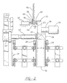
- Figures 1 and 2 illustrate a forming, filling and sealing machine 10 embodying a pour spout fitment applicator 12, and including a conveyor 14 carrying thermoplastics-coated cartons 16 having open top closures 18.
- An opening 20 (see Figures 3 and 5 ) is formed in a selected panel 22 of each end closure 18.
- the applicator 12 is mounted on the machine 10 intermediate the usual indexable turret mechanism T including a plurality of mandrels M and a filling station including a source S of a selected liquid product.
- the conveyor 14 comprises two endless chains 24 and 26 spaced a predetermined distance d apart, within which a series of closely spaced-apart cartons 16 are carried, with the panel 22 bearing the opening 20 facing toward one chain 24.
- the pour spout fitment applicator 12 is positioned to receive two pour spout fitments 28 at a time on its two exposed arms 32 and 34 at stage 101, while two fitments on its two inner arms 36 and 38 are positioned for placement, as will be explained, into two top panels 22 of adjacent cartons 16 and 16a during a dwell while being conveyed by the double indexing conveyor 14 ( Figure 2 ).
- the arm 32 will rotate toward and into carton 16B.
- the arm 34 rotates into carton 16C.
- the arms 32 and 34 will become aligned with the openings 20 in the top panels 22 of the cartons 16B and 16C for placement of two fitments 28 therein, with the arms 36 and 38 now being in the location for receiving two more fitments 28 for the next cycle.
- each carton 16 has indexed through a distance of 7.0 inches (17.78cm.) for a quart processing machine, or 9.0 inches (22.86cm.) for a half-gallon processing machine, in moving from stage 101 to stage 115, along the conveyor 14.
- each of two tracks 46 in the form of chutes presents a pour spout fitment 28 at a spacing d ' from an aligned, extension-type receiver or spigot 50 of one of the arms of the applicator 12.
- a piston 40 of a suitable, pneumatic, piston-and-cylinder device 42 having a flanged end 44, which, for some fitment sizes, may include a cylindrical shape for surrounding the fitment 28, serves to push each end fitment from the track 46 onto the spigot 50 of the applicator arm.
- Each spigot 50 has an elastomeric ring 52 therearound which will assume an interference fit in the inner periphery of the flanged end of the fitment 28.
- Each track 46 extends vertically downwardly at the end thereof to terminate adjacent the applicator 12 and is adapted to hold a row of pour spout fitments 28, each having a flange 54 thereon slidably aligned end-to-end in the track, as received from suitable external loading means.
- suitable external loading means may include a vibratory parts feeder (not shown), known to have been available from Syntron Co., Homer City, State of Pennsylvania, United States of America.
- Such a parts feeder automatically orients a load of flanged fitments 28 and feeds them in their oriented attitude to each track 46.
- a pair of tracks may extend from one parts feeder bowl, or from a pair of feeder bowls.
- the flange 54 of the fitment 28 is confined within the edges of the track 46, illustrated diagrammatically in Figure 2 , and is snapped outwardly therefrom upon the fitment being pushed by the flanged end 44 of the piston 40.
- a drive unit, represented as 56, is connected by a shaft 58 to the centre of the applicator 12.
- the drive unit 56 is adapted to reciprocate the applicator 12 within the distance d , and to rotate the applicator through repeated 180° cycles shown in Figure 3 .
- the two arms 32 and 34 While moving laterally to place two fitments 28 into two openings 20 in two adjacent panels 22 from the arms 36 and 38, the two arms 32 and 34 extend toward two other fitments 28 in the two adjacent tracks 46, stopping the distance d ' away therefrom to await the conveyance of the fitments by the pistons 40 and ends 44.
- the application station includes two ultrasonic sealers 60 ( Figure 2 ), each including a retractable horn 62 having an axis aligned with the opening 20 through the panel 22.
- the two vibrating horns 62 engage the outer surfaces of the two panels 22, opposite the flanges 54, thereby to bond the flanges to the inner surfaces of the two panels. While the bonding process is being accomplished, the ends 44 engage the two adjacent fitments 28 and convey them across the spacing d ' and slide them onto the two spigots 50.
- the horns 62 and the applicator 12 then retract to begin the next cycle.
- placing means 40-44 is usable with an applicator with either two or three arms instead of the four arms described above.
- placing means 40-44 positively applies pour spout fitments to spigots, in contrast to an applicator which depends upon only a friction fit of a spigot first to insert into and then to pull a fitment from a stationary escapement.
Description
- This invention relates generally to a method of applying fitments to containers and to apparatus for use in the method and including a container fitment applicator, especially to such applicators for use on carton forming, filling and sealing machines and, more particularly, to such machines in which pour spout fitments are applied while the cartons are being processed thereon.
- Forming, filling and sealing machines having pour spout applicators at one of the stations therealong are known. For example,
GB-A-2,238,287 -
US-A-5,484,374 discloses an applicator including a rotatable and translatable anvil having three (or more or fewer) radially extending arms. A mandrel on one arm frictionally engages a pour spout fitment simultaneously with a second mandrel inserting a fitment into a container hole. The applicator relies upon the friction between the interior surface of the fitment and the closely-fitting first mandrel to overcome suction imparted through an aperture in an escapement holding the fitment to withdraw the fitment from the escapement. An ultrasonic sealer vibrates the container wall against the anvil to weld the fitment to the container. The applicator applies one fitment to one container at a time. - Other pouring spout applicators are disclosed in
US-A-4,788,811 andUS-A-4,386,923 .US-A-4,788,811 discloses a horizontally elongated pour spout fitment attaching turret at a location upstream of the usual turret and radial mandrels on which the bottom end closure is folded and sealed. The fitment attaching turret includes a pusher at one station for pushing an open-ended package onto a sucker device holding and inserting a pour spout fitment into an opening in a package top panel. The fitment attaching turret is then rotated to a second station where an anvil is axially inserted into the package, co-operable with an ultrasonic horn for sealing a flange of the fitment to the inner surface of the top panel. -
US-A-4,386,923 discloses a bag-in-box arrangement wherein a fitment is attached to the bag which is then inserted through a hole in a flap of the box, while both are in the collapsed or blank state. - Each of
US-A-5,267,934 andUS-A-5,435,803 discloses pour spout fitment applicators wherein the fitment is applied from within the carton, outwardly through an opening therein. - Furthermore,
WO95/10408A - According to a first aspect of the present invention, there is provided apparatus for use in applying fitments to containers as defined in claim 1.
- According to a second aspect of the present invention, there is provided a method of applying fitments to containers as defined in claim 4.
- Owing to the present invention, it is possible to place the fitments positively on the receiving means and so ensure that the fitments are reliably and correctly received by the applicator.
- Advantageously, the arms comprise first, second, third and fourth arms, and the driving means is arranged to rotate the applicator so as angularly to position the first and second arms carrying respective first and second fitments ready for concurrent applying of the first and second fitments to respective first and second containers and so as angularly to position the third and fourth arms to receive respective third and fourth fitments.
- Thereby, it is possible to provide improved application of fitments to containers on a packaging machine, particularly a carton forming, filling and sealing machine, on which containers are indexed in groups.
- The apparatus is particularly applicable to circumstances where containers aligned with the applicator are closely arrayed.
- In a preferred embodiment, the apparatus includes a four-armed pour spout fitment applicator which rotates two of its arms into open-topped cartons and applies two flanged pour spout fitments outwardly through openings in a pair of top panels of a pair of adjacent cartons, while its other two arms are positioned to receive two other fitments. A pair of pneumatic piston-and-cylinder devices serve to transport the two other fitments to the other two arms and positively place the same thereon. An external ultrasonic sealer includes a horn which serves to engage the outer panel surfaces to seal the flanges of the fitments to the inner surfaces of the top panels around the openings while the pair of piston-and-cylinder devices are being actuated.
- In order that the invention may be clearly understood and readily carried into effect, reference will now be made, by way of example, to the accompanying drawings, in which:-
-
Figure 1 is a side elevation of a double indexing, forming, filling and sealing machine; -
Figure 2 is an enlarged side elevation of a pour spout fitment application station of the machine; -
Figure 3 is a schematic, side elevational representation of fifteen operational stages at the station; -
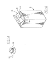
Figure 4 is a perspective view of a pour spout fitment applicable at the station; and -
Figure 5 is a perspective view of a package produced by the machine. - Referring to the drawings,
Figures 1 and2 illustrate a forming, filling andsealing machine 10 embodying a pourspout fitment applicator 12, and including aconveyor 14 carrying thermoplastics-coatedcartons 16 having opentop closures 18. An opening 20 (seeFigures 3 and5 ) is formed in a selectedpanel 22 of eachend closure 18. Theapplicator 12 is mounted on themachine 10 intermediate the usual indexable turret mechanism T including a plurality of mandrels M and a filling station including a source S of a selected liquid product. - As shown in
Figure 2 , theconveyor 14 comprises twoendless chains cartons 16 are carried, with thepanel 22 bearing the opening 20 facing toward onechain 24. - As seen in
Figure 3 , the pourspout fitment applicator 12 is positioned to receive twopour spout fitments 28 at a time on its two exposedarms stage 101, while two fitments on its twoinner arms top panels 22 ofadjacent cartons 16 and 16a during a dwell while being conveyed by the double indexing conveyor 14 (Figure 2 ). As theconveyor 14 moves throughstages 102 to 106, thearm 32 will rotate toward and intocarton 16B. During further movement of theconveyor 14 throughstages 107 to 110, thearm 34 rotates intocarton 16C. During further movement through stages 111 to 115, thearms openings 20 in thetop panels 22 of thecartons fitments 28 therein, with thearms more fitments 28 for the next cycle. - As shown in
Figure 3 , thearm 32 has rotated through 180° for the cycle fromstage 101 tostage 115. Its next 180° rotation will bring thearm 32 back to thestage 101 position, to receive its nextpour spout fitment 28. It has been determined, in the example shown, that eachcarton 16 has indexed through a distance of 7.0 inches (17.78cm.) for a quart processing machine, or 9.0 inches (22.86cm.) for a half-gallon processing machine, in moving fromstage 101 tostage 115, along theconveyor 14. - Referring once again to
Figure 2 , each of twotracks 46 in the form of chutes presents apour spout fitment 28 at a spacing d' from an aligned, extension-type receiver orspigot 50 of one of the arms of theapplicator 12. Apiston 40 of a suitable, pneumatic, piston-and-cylinder device 42, having aflanged end 44, which, for some fitment sizes, may include a cylindrical shape for surrounding thefitment 28, serves to push each end fitment from thetrack 46 onto thespigot 50 of the applicator arm. Eachspigot 50 has anelastomeric ring 52 therearound which will assume an interference fit in the inner periphery of the flanged end of thefitment 28. - Each
track 46 extends vertically downwardly at the end thereof to terminate adjacent theapplicator 12 and is adapted to hold a row ofpour spout fitments 28, each having aflange 54 thereon slidably aligned end-to-end in the track, as received from suitable external loading means. Such loading means may include a vibratory parts feeder (not shown), known to have been available from Syntron Co., Homer City, State of Pennsylvania, United States of America. Such a parts feeder automatically orients a load offlanged fitments 28 and feeds them in their oriented attitude to eachtrack 46. A pair of tracks may extend from one parts feeder bowl, or from a pair of feeder bowls. - The
flange 54 of thefitment 28 is confined within the edges of thetrack 46, illustrated diagrammatically inFigure 2 , and is snapped outwardly therefrom upon the fitment being pushed by theflanged end 44 of thepiston 40. - A drive unit, represented as 56, is connected by a
shaft 58 to the centre of theapplicator 12. Thedrive unit 56 is adapted to reciprocate theapplicator 12 within the distance d, and to rotate the applicator through repeated 180° cycles shown inFigure 3 . - While moving laterally to place two
fitments 28 into twoopenings 20 in twoadjacent panels 22 from thearms arms other fitments 28 in the twoadjacent tracks 46, stopping the distance d' away therefrom to await the conveyance of the fitments by thepistons 40 andends 44. - The application station includes two ultrasonic sealers 60 (
Figure 2 ), each including aretractable horn 62 having an axis aligned with theopening 20 through thepanel 22. As theapplicator 12 places the twofitments 28 into twoopenings 20, the two vibratinghorns 62 engage the outer surfaces of the twopanels 22, opposite theflanges 54, thereby to bond the flanges to the inner surfaces of the two panels. While the bonding process is being accomplished, theends 44 engage the twoadjacent fitments 28 and convey them across the spacing d' and slide them onto the twospigots 50. - The
horns 62 and theapplicator 12 then retract to begin the next cycle. - It should be apparent that there has been described with reference to the drawings an improved carton pour spout fitment applicator that is co-operable with a double indexing conveyor of a high-production, forming, filling and sealing machine.
- It should be further apparent that, for a machine which indexes closely arrayed cartons two at a time along one path, only one applicator is employed to serve two adjacent cartons. For such a machine, there would be a dual-mandrel turret, or a single-mandrel turret and a single-to-dual indexing
carton transfer mechanism 64 as shown inFigure 1 , and as disclosed inUS-A-4,456,118 , with, of course, downstream multiple breakers, fillers, folders and sealers. - It should also be apparent that the placing means 40-44 is usable with an applicator with either two or three arms instead of the four arms described above.
- It should be still further apparent that the placing means 40-44 positively applies pour spout fitments to spigots, in contrast to an applicator which depends upon only a friction fit of a spigot first to insert into and then to pull a fitment from a stationary escapement.
Claims (7)
- Apparatus for use in applying fitments to containers, comprising an applicator (12) having at least two arms (32-38) distributed about an axis (58) and each having in a distal end zone thereof receiving means (50) to receive and carry a fitment (28), including a sealing flange (54), driving means (56) arranged to rotate said applicator (12) to cause one arm (32) carrying one fitment (28) to align said one fitment (28) with one container (16B) while placing the receiving means of another arm (36) in position to receive another fitment (28) from an adjacent track (46), and also arranged to move the applicator (12) axially to apply said one fitment (28) to said one container (16B) and to bring the receiving means (50) of said other arm (36) to a forward end position (Figure 2), and placing means (40-44) for engaging said other fitment (28) and moving said other fitment (28) from said track (46) towards said other arm (36) characterized in that said forward end position (Figure 2) is at a predetermined spacing (d') from a waiting position in said track (46) of the sealing flange (54) of said other fitment (28).
- Apparatus according to claim 1, and further comprising fixing means (62) for fixing said one fitment (28) to said one container (16B), said placing means (40-44) being arranged to move said other fitment (28) from said track (46) to said other arm (36) in a timed relationship with the fixing of said one fitment (28) to said one container (16B).
- Apparatus according to claim 1 or 2, wherein said placing means (40-44) includes a piston (40) having end means (44) for abutting against a body of said other fitment (28) and causing a flange (54) on said body to snap out of said track (46) and move through said predetermined distance (d') to mount said other fitment (28) slidably onto the receiving means (50) of said other arm (36).
- A method of applying to containers fitment including respective sealing flanges, comprising turning an applicator (12) including a plurality of arms (32-38) so as to bring one receiving means (50) of one (32) of the arms (32-38) to a forward end position (Figure 2) constituting a receiving position to receive one fitment (28), placing said one fitment (28) on said one receiving means (50), further turning the applicator (12) to bring said one receiving means (50) and thus said one fitment (28) to a delivering position to deliver said one fitment (28), applying said one fitment (28) to one container (16B) and at the same time bringing another receiving means (50) of another (36) of said arms (32-38) to a forward end position (Figure 2) constituting a receiving position to receive another fitment (28), and placing said other fitment (28) onto said other receiving means (50), characterized in that each said forward end position (Figure 2) is at a predetermined spacing (d') from a waiting position in said track (46) of the sealing flange (54) of the fitment (28), and said placing of said other fitment (28) is performed by moving said other fitment (28) onto said other receiving means (50).
- A method according to claim 4, and further comprising, after said applying, fixing said one fitment (28) to said one container (16B), said placing of said other fitment (28) being performed in a timed relationship with said fixing.
- A method according to claim 5, wherein said applying is performed by axially advancing said applicator (12), and said applicator (12) is axially retracted following said fixing.
- A method according to claim 5 or 6, wherein said placing and said fixing are concurrent.
Applications Claiming Priority (3)
| Application Number | Priority Date | Filing Date | Title |
|---|---|---|---|
| US680901 | 1996-07-16 | ||
| US08/680,901 US5964687A (en) | 1996-07-16 | 1996-07-16 | Container fitment applicator |
| EP97304990A EP0819611B1 (en) | 1996-07-16 | 1997-07-08 | Container fitment application |
Related Parent Applications (2)
| Application Number | Title | Priority Date | Filing Date |
|---|---|---|---|
| EP97304990A Division EP0819611B1 (en) | 1996-07-16 | 1997-07-08 | Container fitment application |
| EP97304990A Division-Into EP0819611B1 (en) | 1996-07-16 | 1997-07-08 | Container fitment application |
Publications (3)
| Publication Number | Publication Date |
|---|---|
| EP0962391A1 EP0962391A1 (en) | 1999-12-08 |
| EP0962391B1 EP0962391B1 (en) | 2005-11-23 |
| EP0962391B9 true EP0962391B9 (en) | 2008-10-15 |
Family
ID=24732991
Family Applications (2)
| Application Number | Title | Priority Date | Filing Date |
|---|---|---|---|
| EP97304990A Expired - Lifetime EP0819611B1 (en) | 1996-07-16 | 1997-07-08 | Container fitment application |
| EP99116441A Revoked EP0962391B9 (en) | 1996-07-16 | 1997-07-08 | A method of applying fitments to containers and apparatus for use in the same |
Family Applications Before (1)
| Application Number | Title | Priority Date | Filing Date |
|---|---|---|---|
| EP97304990A Expired - Lifetime EP0819611B1 (en) | 1996-07-16 | 1997-07-08 | Container fitment application |
Country Status (6)
| Country | Link |
|---|---|
| US (1) | US5964687A (en) |
| EP (2) | EP0819611B1 (en) |
| JP (1) | JPH1077012A (en) |
| CN (2) | CN1101326C (en) |
| DE (2) | DE69734726T2 (en) |
| PL (1) | PL188362B1 (en) |
Families Citing this family (22)
| Publication number | Priority date | Publication date | Assignee | Title |
|---|---|---|---|---|
| US5704541A (en) * | 1996-04-25 | 1998-01-06 | Tetra Laval Holdings & Finance S.A. | Flat-top container with an opening fitment |
| EP1293435A1 (en) | 1997-10-24 | 2003-03-19 | Elopak Systems Ag | Machine for applying parts to material |
| US5983599A (en) * | 1998-04-23 | 1999-11-16 | Tetra Laval Holdings & Finance, S.A. | Offset rotary anvils for applying fitments to carton |
| JP2000000900A (en) * | 1998-06-15 | 2000-01-07 | Shikoku Kakoki Co Ltd | Apparatus for sealing container pouring cylinder |
| US6269935B1 (en) * | 1999-07-23 | 2001-08-07 | Elopak Systems Ag | High speed cap applicator cap holder |
| US6468005B1 (en) * | 2000-08-24 | 2002-10-22 | Elopak Systems Ag | Apparatus for conveying and separating articles through a transport tube |
| JP4639479B2 (en) * | 2001-01-26 | 2011-02-23 | 四国化工機株式会社 | Container cap attachment device |
| DE10133809A1 (en) * | 2001-07-11 | 2003-01-23 | Bericap Gmbh & Co Kg | Spout for drinks carton comprises tube with peripheral flange, tags which project inwards at angle holding spout in position |
| US6463715B1 (en) | 2001-10-12 | 2002-10-15 | Tetra Laval Holdings & Finance, Sa | Rotary closure applicator |
| SE524200C2 (en) * | 2002-02-19 | 2004-07-06 | Trepak Internat Ab | Mechanism and method of encapsulation |
| GB0230237D0 (en) * | 2002-12-28 | 2003-02-05 | Elopak Systems | Apparatus and method |
| US7500940B2 (en) * | 2004-10-05 | 2009-03-10 | Nimco Corporation | Spout applicator |
| EP1812296B1 (en) * | 2004-11-16 | 2009-04-29 | Elopak Systems Ag | Apparatus and method for use in applying fitments to containers |
| SE529720C2 (en) * | 2006-03-10 | 2007-11-06 | Tetra Laval Holdings & Finance | Method of manufacturing a package |
| DE202007004200U1 (en) * | 2007-03-19 | 2007-06-21 | Induflex Robert Morgan, E.K. | Spigot-device for receiving sealing cap of beverage container, includes ring acted on by spring positioned within ring |
| NO326538B1 (en) * | 2007-05-03 | 2008-12-29 | Stein Vidar Andersen | Closure applicator anvil device |
| DE102010029360A1 (en) * | 2009-09-30 | 2011-03-31 | Robert Bosch Gmbh | Apparatus and method for molding, filling and closing of each Ausgießeinrichtung having bags |
| DE102010050483A1 (en) * | 2010-11-08 | 2012-05-10 | Elopak Systems Ag | Filling machine and a method for operating a filling machine |
| DE102012112792A1 (en) * | 2012-12-20 | 2014-06-26 | Elopak Systems Ag | Method and device for conveying piece goods in a filling machine |
| IL245710A0 (en) * | 2016-05-18 | 2016-08-31 | Real Cap Ltd | Pour spout, spigot and method for usage thereof |
| CN105905366B (en) * | 2016-06-27 | 2019-04-02 | 薛桦钧 | The sealed in unit of roof packet |
| CN107472604B (en) * | 2017-07-12 | 2019-08-27 | 天津比朗德机械制造有限公司 | A kind of automatic lid placing device |
Family Cites Families (12)
| Publication number | Priority date | Publication date | Assignee | Title |
|---|---|---|---|---|
| US3812572A (en) * | 1973-02-14 | 1974-05-28 | Gen Films Inc | Tube applicator |
| DE3163709D1 (en) * | 1980-02-22 | 1984-06-28 | Dainippon Printing Co Ltd | Method and apparatus for the fabrication of a bag-in-box package |
| US4456118A (en) * | 1981-11-18 | 1984-06-26 | Ex-Cell-O Corporation | Single to dual indexing carton transfer mechanism |
| US4788811A (en) * | 1986-05-17 | 1988-12-06 | Dai Nippon Insatsu Kabushiki Kaisha | Process and apparatus for assembling and liquor-charging of packages of paper and the like |
| GB8926635D0 (en) * | 1989-11-24 | 1990-01-17 | Rutter Raymond | Cap and pour spout applicator |
| US5484374A (en) * | 1991-10-25 | 1996-01-16 | Nimco Corporation | Method and apparatus for attaching a spout to a container |
| US5267934A (en) * | 1993-04-12 | 1993-12-07 | Elopak Systems A.G. | Carton pour spout fitment applicator |
| US5366433A (en) * | 1993-06-24 | 1994-11-22 | Mccormick Charles M | Safety clutch and its use in capping milk cartons |
| US5435803A (en) * | 1993-07-01 | 1995-07-25 | Elopak Systems A.G. | Container fitment applicator |
| AU7962794A (en) * | 1993-10-15 | 1995-05-04 | Portola Packaging, Inc. | Apparatus and method for attaching fitments to cartons |
| US5473857A (en) * | 1993-11-16 | 1995-12-12 | International Paper Company | System integration for hot melt sealing of fitments in-line with form/fill/seal machine |
| US5601669A (en) * | 1994-10-04 | 1997-02-11 | Portola Packaging, Inc. | Apparatus and method for attaching fitments to cartons |
-
1996
- 1996-07-16 US US08/680,901 patent/US5964687A/en not_active Expired - Lifetime
-
1997
- 1997-07-08 DE DE69734726T patent/DE69734726T2/en not_active Revoked
- 1997-07-08 EP EP97304990A patent/EP0819611B1/en not_active Expired - Lifetime
- 1997-07-08 DE DE69701599T patent/DE69701599T2/en not_active Expired - Lifetime
- 1997-07-08 EP EP99116441A patent/EP0962391B9/en not_active Revoked
- 1997-07-09 PL PL97321038A patent/PL188362B1/en unknown
- 1997-07-14 JP JP9202664A patent/JPH1077012A/en active Pending
- 1997-07-16 CN CN97115415A patent/CN1101326C/en not_active Expired - Lifetime
- 1997-07-16 CN CNB021543429A patent/CN1180957C/en not_active Expired - Fee Related
Also Published As
| Publication number | Publication date |
|---|---|
| JPH1077012A (en) | 1998-03-24 |
| DE69701599D1 (en) | 2000-05-11 |
| MX9705367A (en) | 1998-07-31 |
| DE69701599T2 (en) | 2000-11-23 |
| EP0962391B1 (en) | 2005-11-23 |
| CN1180957C (en) | 2004-12-22 |
| US5964687A (en) | 1999-10-12 |
| PL188362B1 (en) | 2005-01-31 |
| PL321038A1 (en) | 1998-01-19 |
| EP0819611A3 (en) | 1998-05-06 |
| EP0962391A1 (en) | 1999-12-08 |
| EP0819611B1 (en) | 2000-04-05 |
| CN1445140A (en) | 2003-10-01 |
| DE69734726T2 (en) | 2006-08-10 |
| DE69734726D1 (en) | 2005-12-29 |
| EP0819611A2 (en) | 1998-01-21 |
| CN1173426A (en) | 1998-02-18 |
| CN1101326C (en) | 2003-02-12 |
Similar Documents
| Publication | Publication Date | Title |
|---|---|---|
| EP0962391B9 (en) | A method of applying fitments to containers and apparatus for use in the same | |
| EP0749904B1 (en) | Container fitment applicator and corresponding method | |
| US5435803A (en) | Container fitment applicator | |
| EP0781228B1 (en) | System for attaching fitments to cartons | |
| US5473857A (en) | System integration for hot melt sealing of fitments in-line with form/fill/seal machine | |
| US6085489A (en) | Spout mandrel with energy ring | |
| US8104250B2 (en) | Apparatus for use in and method of attachiing cap-form fitments to containers | |
| AU739136B2 (en) | Apparatus and methods for securing articles to containers | |
| US7867156B2 (en) | Spout applicator | |
| US5819504A (en) | Process and apparatus for applying fitments to a carton | |
| EP1091874B1 (en) | Method and packaging machine for forming a container | |
| US5983599A (en) | Offset rotary anvils for applying fitments to carton | |
| MXPA97005367A (en) | Accessory applicator for contene | |
| JPH07112497A (en) | Manufacture of fluid storage container | |
| WO1999065669A1 (en) | A method and device for a packaging machine |
Legal Events
| Date | Code | Title | Description |
|---|---|---|---|
| PUAI | Public reference made under article 153(3) epc to a published international application that has entered the european phase |
Free format text: ORIGINAL CODE: 0009012 |
|
| AC | Divisional application: reference to earlier application |
Ref document number: 819611 Country of ref document: EP |
|
| AK | Designated contracting states |
Kind code of ref document: A1 Designated state(s): DE GB IT SE |
|
| 17P | Request for examination filed |
Effective date: 20000602 |
|
| AKX | Designation fees paid |
Free format text: DE GB IT SE |
|
| 17Q | First examination report despatched |
Effective date: 20001012 |
|
| GRAP | Despatch of communication of intention to grant a patent |
Free format text: ORIGINAL CODE: EPIDOSNIGR1 |
|
| GRAS | Grant fee paid |
Free format text: ORIGINAL CODE: EPIDOSNIGR3 |
|
| GRAA | (expected) grant |
Free format text: ORIGINAL CODE: 0009210 |
|
| AC | Divisional application: reference to earlier application |
Ref document number: 0819611 Country of ref document: EP Kind code of ref document: P |
|
| AK | Designated contracting states |
Kind code of ref document: B1 Designated state(s): DE GB IT SE |
|
| REG | Reference to a national code |
Ref country code: GB Ref legal event code: FG4D |
|
| REF | Corresponds to: |
Ref document number: 69734726 Country of ref document: DE Date of ref document: 20051229 Kind code of ref document: P |
|
| REG | Reference to a national code |
Ref country code: SE Ref legal event code: TRGR |
|
| PLBI | Opposition filed |
Free format text: ORIGINAL CODE: 0009260 |
|
| PLAX | Notice of opposition and request to file observation + time limit sent |
Free format text: ORIGINAL CODE: EPIDOSNOBS2 |
|
| 26 | Opposition filed |
Opponent name: SIG TECHNOLOGY AG Effective date: 20060809 |
|
| PLAF | Information modified related to communication of a notice of opposition and request to file observations + time limit |
Free format text: ORIGINAL CODE: EPIDOSCOBS2 |
|
| PLBB | Reply of patent proprietor to notice(s) of opposition received |
Free format text: ORIGINAL CODE: EPIDOSNOBS3 |
|
| PLCK | Communication despatched that opposition was rejected |
Free format text: ORIGINAL CODE: EPIDOSNREJ1 |
|
| APBP | Date of receipt of notice of appeal recorded |
Free format text: ORIGINAL CODE: EPIDOSNNOA2O |
|
| APAH | Appeal reference modified |
Free format text: ORIGINAL CODE: EPIDOSCREFNO |
|
| APBQ | Date of receipt of statement of grounds of appeal recorded |
Free format text: ORIGINAL CODE: EPIDOSNNOA3O |
|
| APBU | Appeal procedure closed |
Free format text: ORIGINAL CODE: EPIDOSNNOA9O |
|
| PGFP | Annual fee paid to national office [announced via postgrant information from national office to epo] |
Ref country code: SE Payment date: 20100715 Year of fee payment: 14 Ref country code: IT Payment date: 20100731 Year of fee payment: 14 Ref country code: DE Payment date: 20100723 Year of fee payment: 14 |
|
| PGFP | Annual fee paid to national office [announced via postgrant information from national office to epo] |
Ref country code: GB Payment date: 20100722 Year of fee payment: 14 |
|
| RDAF | Communication despatched that patent is revoked |
Free format text: ORIGINAL CODE: EPIDOSNREV1 |
|
| RDAG | Patent revoked |
Free format text: ORIGINAL CODE: 0009271 |
|
| STAA | Information on the status of an ep patent application or granted ep patent |
Free format text: STATUS: PATENT REVOKED |
|
| 27W | Patent revoked |
Effective date: 20100923 |
|
| GBPR | Gb: patent revoked under art. 102 of the ep convention designating the uk as contracting state |
Effective date: 20100923 |
|
| POAG | Date of filing of petition for review recorded |
Free format text: ORIGINAL CODE: EPIDOSNPRV3 |
|
| POAH | Number of petition for review recorded |
Free format text: ORIGINAL CODE: EPIDOSNPRV1 |
|
| POAI | Petitioner in petition for review recorded |
Free format text: ORIGINAL CODE: EPIDOSNPRV2 |
|
| REG | Reference to a national code |
Ref country code: SE Ref legal event code: ECNC |
|
| POAK | Decision taken: petition for review obviously unsubstantiated |
Free format text: ORIGINAL CODE: 0009255 |
|
| PRVN | Petition for review not allowed |
Free format text: PETITION FOR REVIEW OBVIOUSLY UNSUBSTANTIATED Effective date: 20120416 |
|
| REG | Reference to a national code |
Ref country code: SE Ref legal event code: ECNC |