EP0962345B1 - A condenser for an air conditioning system for a vehicle, having an integral accumulator/expansion tank - Google Patents
A condenser for an air conditioning system for a vehicle, having an integral accumulator/expansion tank Download PDFInfo
- Publication number
- EP0962345B1 EP0962345B1 EP99830244A EP99830244A EP0962345B1 EP 0962345 B1 EP0962345 B1 EP 0962345B1 EP 99830244 A EP99830244 A EP 99830244A EP 99830244 A EP99830244 A EP 99830244A EP 0962345 B1 EP0962345 B1 EP 0962345B1
- Authority
- EP
- European Patent Office
- Prior art keywords
- accumulator
- condenser
- expansion tank
- heat exchanger
- exchanger core
- Prior art date
- Legal status (The legal status is an assumption and is not a legal conclusion. Google has not performed a legal analysis and makes no representation as to the accuracy of the status listed.)
- Expired - Lifetime
Links
Images


Classifications
-
- B—PERFORMING OPERATIONS; TRANSPORTING
- B60—VEHICLES IN GENERAL
- B60H—ARRANGEMENTS OF HEATING, COOLING, VENTILATING OR OTHER AIR-TREATING DEVICES SPECIALLY ADAPTED FOR PASSENGER OR GOODS SPACES OF VEHICLES
- B60H1/00—Heating, cooling or ventilating devices
- B60H1/32—Cooling devices
- B60H1/3204—Cooling devices using compression
- B60H1/3227—Cooling devices using compression characterised by the arrangement or the type of heat exchanger, e.g. condenser, evaporator
-
- B—PERFORMING OPERATIONS; TRANSPORTING
- B60—VEHICLES IN GENERAL
- B60H—ARRANGEMENTS OF HEATING, COOLING, VENTILATING OR OTHER AIR-TREATING DEVICES SPECIALLY ADAPTED FOR PASSENGER OR GOODS SPACES OF VEHICLES
- B60H1/00—Heating, cooling or ventilating devices
- B60H1/32—Cooling devices
- B60H1/3204—Cooling devices using compression
- B60H1/3229—Cooling devices using compression characterised by constructional features, e.g. housings, mountings, conversion systems
-
- F—MECHANICAL ENGINEERING; LIGHTING; HEATING; WEAPONS; BLASTING
- F25—REFRIGERATION OR COOLING; COMBINED HEATING AND REFRIGERATION SYSTEMS; HEAT PUMP SYSTEMS; MANUFACTURE OR STORAGE OF ICE; LIQUEFACTION SOLIDIFICATION OF GASES
- F25B—REFRIGERATION MACHINES, PLANTS OR SYSTEMS; COMBINED HEATING AND REFRIGERATION SYSTEMS; HEAT PUMP SYSTEMS
- F25B39/00—Evaporators; Condensers
- F25B39/04—Condensers
-
- F—MECHANICAL ENGINEERING; LIGHTING; HEATING; WEAPONS; BLASTING
- F25—REFRIGERATION OR COOLING; COMBINED HEATING AND REFRIGERATION SYSTEMS; HEAT PUMP SYSTEMS; MANUFACTURE OR STORAGE OF ICE; LIQUEFACTION SOLIDIFICATION OF GASES
- F25B—REFRIGERATION MACHINES, PLANTS OR SYSTEMS; COMBINED HEATING AND REFRIGERATION SYSTEMS; HEAT PUMP SYSTEMS
- F25B2339/00—Details of evaporators; Details of condensers
- F25B2339/04—Details of condensers
- F25B2339/044—Condensers with an integrated receiver
-
- F—MECHANICAL ENGINEERING; LIGHTING; HEATING; WEAPONS; BLASTING
- F25—REFRIGERATION OR COOLING; COMBINED HEATING AND REFRIGERATION SYSTEMS; HEAT PUMP SYSTEMS; MANUFACTURE OR STORAGE OF ICE; LIQUEFACTION SOLIDIFICATION OF GASES
- F25B—REFRIGERATION MACHINES, PLANTS OR SYSTEMS; COMBINED HEATING AND REFRIGERATION SYSTEMS; HEAT PUMP SYSTEMS
- F25B2339/00—Details of evaporators; Details of condensers
- F25B2339/04—Details of condensers
- F25B2339/044—Condensers with an integrated receiver
- F25B2339/0443—Condensers with an integrated receiver the receiver being positioned horizontally
Definitions
- the present invention relates to a condenser for an air conditioning system for a vehicle, comprising:
- An air conditioning system for vehicles is - essentially formed by a closed circuit in which are inserted, in series to each other, a compressor, a condenser, an expansion valve and a cooler.
- a dehydrating device and an accumulator which has the purpose of compensating leakages of cooling fluid, filling tolerances and variations of thermal load.
- both the function of accumulator and dehydrating device are concentrated in a single separate component formed by a sealed body having a capacity sufficient to carry out the function of accumulator and housing a filter and a certain quantity of dehydrating material.
- the condenser is mounted on the vehicle with the distributors oriented vertically, in correspondence with the front end of the vehicle engine compartment.
- the horizontal dimension of the condenser is a critical factor which is conditioned by the front curvature of the vehicle.
- US-A-5172758 discloses in the embodiment of figure 12 a condenser having the features of the preamble of claim 1.
- the accumulator/expansion tank of the system extends orthogonally to the two distributors, along one of the sides of the heat exchanger core.
- the subject of the present invention is a condenser according to claim 1.
- an air conditioning system for vehicles comprises a closed circuit in which are arranged in series to each other a compressor 12, a condenser 14 a dehydrating device 16 including a filter, an expansion valve 18 and a cooler 20.
- the condenser 14 comprises a heat exchanger core 22 formed, in a way per se known, by a plurality of tubes and fins forming a generically a rectangularly shaped structure.
- the condenser 14 comprises a pair of distributors 24, 26 formed by tubular elements connected to the tubes of the heat exchanger core 22 so as to establish fluid communication therewith.
- the two distributors 24, 26 are parallel to each other and are arranged along two opposite sides of the heat exchanger core 22.
- the condenser 14 is provided with an integral accumulator expansion tank 28 formed by a tubular element extending along one of the sides of the heat exchanger core 22 orthogonal to the distributors 24, 26.
- the distributor 26 and the accumulator 28 are formed by a single tubular element bent approximately at 90° and closed at both ends indicated 30 and 32.
- a fitting for the fluid outlet, schematically indicated 34, can be applied e.g. by welding on the outer wall of the distributor 26 (figure 2) or in correspondence with the curve connecting the distributor 26 to the accumulator 28 (figure 3).
- the distributor 26 and the accumulator 28 could be formed by two different tubular elements welded to each other.
- the tubular element forming the accumulator 28 is closed at both ends 32, 36 whereas the tubular element forming the distributor 26 is closed at the lower end 30 and the open upper end is inserted into a hole formed in the lateral wall of the tubular element 28.
- Figure 5 shows a solution similar to the one of figure 4, in which the tubular element forming the accumulator 28 has a diameter greater than that of the distributor 26 and a shorter length.
- FIG. 6 is shown the case in which the distributor 26 and the accumulator 28 are formed by two different tubular elements connected to each other by a coupling element 38 fixed (for example by welding) to the open ends of the distributor 26 and accumulator 28 so as to form a liquid-tight connection.
- the ends 30, 32 of the distributor 26, and accumulator 28 are closed.
- the shape and the dimensions of the accumulator 28 can be chosen so as to provide a total volume suitable for the characteristics of the system, which generally must be greater than about 100 cm 2 .
- the tubular element forming the accumulator 28 should have a slight inclination with respect to a horizontal direction and the outlet fitting of the condenser should be placed in correspondence with the lower point of the accumulator 28.
- the outlet fitting 34 of the condenser will always be in communication with the zone of the accumulator in which the liquid is collected, whereas the vapour which is present in the accumulator tends to collect in the upper part of the tubular element 28, which is farther away from the outlet fitting 34.
- Figures 7 and 8 show two possible orientations of the tubular element 28 in which, the outlet fitting is arranged in correspondence with the distributor and, respectively, in correspondence with the end of the - tubular element opposite to the distributor 26.
- the accumulator is inclined towards the outlet prevents flow instabilities and guaranties that the cooling fluid at the exit of the condenser is in a liquid state.
- the inclination of the accumulator 28 with respect to the horizontal is comprised between 2° and 10°.
Landscapes
- Engineering & Computer Science (AREA)
- Physics & Mathematics (AREA)
- Thermal Sciences (AREA)
- Mechanical Engineering (AREA)
- General Engineering & Computer Science (AREA)
- Air-Conditioning For Vehicles (AREA)
- Heat-Exchange Devices With Radiators And Conduit Assemblies (AREA)
Description
- The present invention relates to a condenser for an air conditioning system for a vehicle, comprising:
- a rectangularly shaped heat exchanger core with tubes and fins,
- a pair of distributors parallel to each other and placed on two opposite sides of the heat exchanger core, and
- an accumulator/expansion tank integrally formed with one of said distributors and placed in fluid communication therewith.
- An air conditioning system for vehicles is - essentially formed by a closed circuit in which are inserted, in series to each other, a compressor, a condenser, an expansion valve and a cooler. In the circuit are normally inserted a dehydrating device and an accumulator which has the purpose of compensating leakages of cooling fluid, filling tolerances and variations of thermal load. In conventional solutions, both the function of accumulator and dehydrating device are concentrated in a single separate component formed by a sealed body having a capacity sufficient to carry out the function of accumulator and housing a filter and a certain quantity of dehydrating material.
- Recently, solutions have been presented in which the accumulator of the air conditioning system is integrated in the condenser. Examples of these solutions are disclosed in EP-0668986 and EP-0480330. These two documents disclose a condenser in which one of the distributor is arranged for establishing fluid communication with an auxiliary tubular element which extends parallel to the distributor and which, in use, performs the function of an accumulator. Since the accumulator must have a predetermined minimum capacity which depends on the characteristics of the system, the auxiliary tubular element necessarily involves an increase in the dimensions of the condenser.
- Normally, the condenser is mounted on the vehicle with the distributors oriented vertically, in correspondence with the front end of the vehicle engine compartment. With this arrangement, the horizontal dimension of the condenser is a critical factor which is conditioned by the front curvature of the vehicle.
- The applicant's experience has shown that when the accumulator is arranged parallel to one of the distributors, the installation of the condenser on many types of vehicles becomes very difficult due to the increase of the horizontal dimension of the condenser.
- US-A-5172758 discloses in the embodiment of figure 12 a condenser having the features of the preamble of claim 1. In this prior art solution, the accumulator/expansion tank of the system extends orthogonally to the two distributors, along one of the sides of the heat exchanger core.
- The subject of the present invention is a condenser according to claim 1.
- Characteristics and advantages of the condenser according to the invention will become clear in the course of the detailed description which follows, given purely by way of non-limiting example, with reference to the annexed drawings, in which:
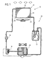
- figure 1 is a schematic view showing an air conditioning system for vehicles provided with a condenser according to the invention,
- figure 2 is a schematic front elevational view of a condenser according to the invention,
- figures 3 to 6 are schematic views showing preferred embodiments of the condenser, and
- figures 7 and 8 are schematic views showing two condensers according to the invention.
- Referring to figure 1, an air conditioning system for vehicles is indicated 10 and comprises a closed circuit in which are arranged in series to each other a
compressor 12, a condenser 14 adehydrating device 16 including a filter, anexpansion valve 18 and acooler 20. Thecondenser 14 comprises aheat exchanger core 22 formed, in a way per se known, by a plurality of tubes and fins forming a generically a rectangularly shaped structure. Thecondenser 14 comprises a pair ofdistributors heat exchanger core 22 so as to establish fluid communication therewith. The twodistributors heat exchanger core 22. - Referring to figures 2 to 6, the
condenser 14 is provided with an integralaccumulator expansion tank 28 formed by a tubular element extending along one of the sides of theheat exchanger core 22 orthogonal to thedistributors - In accordance with figure 2, the
distributor 26 and theaccumulator 28 are formed by a single tubular element bent approximately at 90° and closed at both ends indicated 30 and 32. A fitting for the fluid outlet, schematically indicated 34, can be applied e.g. by welding on the outer wall of the distributor 26 (figure 2) or in correspondence with the curve connecting thedistributor 26 to the accumulator 28 (figure 3). - In alternative, as shown in figure 4, the
distributor 26 and theaccumulator 28 could be formed by two different tubular elements welded to each other. The tubular element forming theaccumulator 28 is closed at bothends distributor 26 is closed at thelower end 30 and the open upper end is inserted into a hole formed in the lateral wall of thetubular element 28. - Figure 5 shows a solution similar to the one of figure 4, in which the tubular element forming the
accumulator 28 has a diameter greater than that of thedistributor 26 and a shorter length. - Finally, as a further preferred, alternative, in figure 6 is shown the case in which the
distributor 26 and theaccumulator 28 are formed by two different tubular elements connected to each other by acoupling element 38 fixed (for example by welding) to the open ends of thedistributor 26 andaccumulator 28 so as to form a liquid-tight connection. Theends distributor 26, andaccumulator 28 are closed. - The shape and the dimensions of the
accumulator 28 can be chosen so as to provide a total volume suitable for the characteristics of the system, which generally must be greater than about 100 cm2. - According to the invention, the tubular element forming the
accumulator 28 should have a slight inclination with respect to a horizontal direction and the outlet fitting of the condenser should be placed in correspondence with the lower point of theaccumulator 28. In this way, the outlet fitting 34 of the condenser will always be in communication with the zone of the accumulator in which the liquid is collected, whereas the vapour which is present in the accumulator tends to collect in the upper part of thetubular element 28, which is farther away from the outlet fitting 34. Figures 7 and 8 show two possible orientations of thetubular element 28 in which, the outlet fitting is arranged in correspondence with the distributor and, respectively, in correspondence with the end of the - tubular element opposite to thedistributor 26. - The fact that the accumulator is inclined towards the outlet prevents flow instabilities and guaranties that the cooling fluid at the exit of the condenser is in a liquid state. Preferably, the inclination of the
accumulator 28 with respect to the horizontal is comprised between 2° and 10°.
Claims (4)
- A condenser for an air conditioning system for a vehicle, comprising:characterized in that the accumulator/expansion tank (28) is inclined with respect to the respective side of the heat exchanger core (22) and in that said outlet fitting (34) of the condenser (14.) is arranged in correspondence with the lower zone of the accumulator (28).a substantially rectangularly shaped heat exchanger core (22) with tubes and fins,a pair of distributors (24, 26) parallel to each other and arranged on two opposite sides of the heat exchanger core (22), the distributors having an inlet fitting and outlet fitting (34), andan accumulator/expansion tank (28) integrally formed with one of said distributors (26), the accumulator/expansion tank having a closed end and an open end placed in fluid communication with a distributor (26), the accumulator/expansion tank (28) extending along one of the sides of the heat exchanger core (22) substantially orthogonal to the distributors (24, 26),
- A condenser according to claim 1, characterized in that the accumulator/expansion tank and the respective distributor (26) are formed by a single tubular element with closed ends and bent substantially at 90°.
- A condenser according to claim 1, characterized in that the accumulator/expansion tank and the respective distributor (26) are formed by two different tubular elements permanently fixed to each other by welding or by means of a coupling element (38).
- A condenser according to claim 1, characterized in that the accumulator/expansion tank (28) forms an angle with respect to the heat exchanger core, comprised between about 2° and 10°.
Applications Claiming Priority (2)
| Application Number | Priority Date | Filing Date | Title |
|---|---|---|---|
| IT98TO000489A ITTO980489A1 (en) | 1998-06-05 | 1998-06-05 | CONDENSER FOR AN AIR CONDITIONING SYSTEM FOR A VEHICLE, HAVING AN INTEGRATED ACCUMULATOR / EXPANSION VESSEL. |
| ITTO980489 | 1998-06-05 |
Publications (2)
| Publication Number | Publication Date |
|---|---|
| EP0962345A1 EP0962345A1 (en) | 1999-12-08 |
| EP0962345B1 true EP0962345B1 (en) | 2002-01-02 |
Family
ID=11416820
Family Applications (1)
| Application Number | Title | Priority Date | Filing Date |
|---|---|---|---|
| EP99830244A Expired - Lifetime EP0962345B1 (en) | 1998-06-05 | 1999-04-23 | A condenser for an air conditioning system for a vehicle, having an integral accumulator/expansion tank |
Country Status (4)
| Country | Link |
|---|---|
| EP (1) | EP0962345B1 (en) |
| DE (1) | DE69900659T2 (en) |
| ES (1) | ES2168161T3 (en) |
| IT (1) | ITTO980489A1 (en) |
Families Citing this family (1)
| Publication number | Priority date | Publication date | Assignee | Title |
|---|---|---|---|---|
| US8166774B2 (en) | 2006-01-25 | 2012-05-01 | Visteon Global Technologies, Inc. | Heat exchanger with an expansion stage |
Family Cites Families (7)
| Publication number | Priority date | Publication date | Assignee | Title |
|---|---|---|---|---|
| US2158388A (en) * | 1938-01-20 | 1939-05-16 | Gen Motors Corp | Surge tank |
| US5172758A (en) * | 1989-02-01 | 1992-12-22 | Sanden Corporation | Condenser with a built-in receiver |
| JP3013492B2 (en) | 1990-10-04 | 2000-02-28 | 株式会社デンソー | Refrigeration apparatus, heat exchanger with modulator, and modulator for refrigeration apparatus |
| US5146767A (en) * | 1991-05-13 | 1992-09-15 | General Motors Corporation | Condenser with dehydrator subcooler |
| JP3301169B2 (en) * | 1992-11-06 | 2002-07-15 | 株式会社デンソー | Refrigeration equipment |
| DE4245046C8 (en) | 1992-11-18 | 2008-08-21 | Behr Gmbh & Co. Kg | Condenser for an air conditioning system of a vehicle |
| FR2709344B1 (en) * | 1993-08-27 | 1995-10-13 | Valeo Thermique Moteur Sa | Condenser for motor vehicle air conditioning system. |
-
1998
- 1998-06-05 IT IT98TO000489A patent/ITTO980489A1/en unknown
-
1999
- 1999-04-23 ES ES99830244T patent/ES2168161T3/en not_active Expired - Lifetime
- 1999-04-23 EP EP99830244A patent/EP0962345B1/en not_active Expired - Lifetime
- 1999-04-23 DE DE69900659T patent/DE69900659T2/en not_active Expired - Lifetime
Also Published As
| Publication number | Publication date |
|---|---|
| ES2168161T3 (en) | 2002-06-01 |
| EP0962345A1 (en) | 1999-12-08 |
| DE69900659T2 (en) | 2002-08-14 |
| ITTO980489A1 (en) | 1999-12-05 |
| DE69900659D1 (en) | 2002-02-21 |
Similar Documents
| Publication | Publication Date | Title |
|---|---|---|
| US6182744B1 (en) | Heat exchanger apparatus including auxiliary radiator for cooling exothermic component | |
| KR100256077B1 (en) | Refrigerant condenser integral with liquid receiver | |
| CN1991288B (en) | Integrated heat exchanger and heat exchanger | |
| US5546761A (en) | Receiver-integrated refrigerant condenser | |
| US5088294A (en) | Condenser with a built-in receiver | |
| EP0930477B1 (en) | Liquid cooled, two phase heat exchanger | |
| JP3996244B2 (en) | Collector heat transfer unit constituting unit and air conditioner | |
| US5394710A (en) | Refrigerating apparatus | |
| US20020056541A1 (en) | Mounting structure for heat exchanger and duplex heat exchanger | |
| JPH11304293A (en) | Refrigerant condenser | |
| JPH07280392A (en) | Refrigerant condenser | |
| US20080041093A1 (en) | Accumulator of air conditioner | |
| US20040089439A1 (en) | Tube-to-tube heat exchanger assembly | |
| US20050279125A1 (en) | Integrated condenser/receiver and insert for use therein | |
| US7264043B2 (en) | Condenser for vehicles and integrated radiator-condenser body including said condenser | |
| JP2000227265A (en) | Recipient integrated refrigerant condenser | |
| JP3557628B2 (en) | Recipient integrated refrigerant condenser | |
| JP2002162134A (en) | Refrigeration cycle device | |
| JP4207333B2 (en) | Condenser with integrated receiver | |
| US6276445B1 (en) | Heat exchanger with heat insulating member disposed between condenser and radiator tanks | |
| JP2000213826A (en) | Recipient integrated refrigerant condenser | |
| JPH08219588A (en) | Liquid receiver integrated refrigerant condenser | |
| EP0962345A1 (en) | A condenser for an air conditioning system for a vehicle, having an integral accumulator/expansion tank | |
| JP3854381B2 (en) | Heat exchanger connection structure | |
| JP2000213825A5 (en) |
Legal Events
| Date | Code | Title | Description |
|---|---|---|---|
| PUAI | Public reference made under article 153(3) epc to a published international application that has entered the european phase |
Free format text: ORIGINAL CODE: 0009012 |
|
| AK | Designated contracting states |
Kind code of ref document: A1 Designated state(s): DE ES FR GB |
|
| AX | Request for extension of the european patent |
Free format text: AL;LT;LV;MK;RO;SI |
|
| 17P | Request for examination filed |
Effective date: 20000107 |
|
| AKX | Designation fees paid |
Free format text: DE ES FR GB |
|
| 17Q | First examination report despatched |
Effective date: 20001227 |
|
| GRAG | Despatch of communication of intention to grant |
Free format text: ORIGINAL CODE: EPIDOS AGRA |
|
| GRAG | Despatch of communication of intention to grant |
Free format text: ORIGINAL CODE: EPIDOS AGRA |
|
| GRAH | Despatch of communication of intention to grant a patent |
Free format text: ORIGINAL CODE: EPIDOS IGRA |
|
| GRAH | Despatch of communication of intention to grant a patent |
Free format text: ORIGINAL CODE: EPIDOS IGRA |
|
| GRAA | (expected) grant |
Free format text: ORIGINAL CODE: 0009210 |
|
| REG | Reference to a national code |
Ref country code: GB Ref legal event code: IF02 |
|
| AK | Designated contracting states |
Kind code of ref document: B1 Designated state(s): DE ES FR GB |
|
| RAP2 | Party data changed (patent owner data changed or rights of a patent transferred) |
Owner name: DENSO THERMAL SYSTEMS S.P.A. |
|
| REF | Corresponds to: |
Ref document number: 69900659 Country of ref document: DE Date of ref document: 20020221 |
|
| REG | Reference to a national code |
Ref country code: ES Ref legal event code: FG2A Ref document number: 2168161 Country of ref document: ES Kind code of ref document: T3 |
|
| ET | Fr: translation filed | ||
| PLBE | No opposition filed within time limit |
Free format text: ORIGINAL CODE: 0009261 |
|
| STAA | Information on the status of an ep patent application or granted ep patent |
Free format text: STATUS: NO OPPOSITION FILED WITHIN TIME LIMIT |
|
| 26N | No opposition filed | ||
| PGFP | Annual fee paid to national office [announced via postgrant information from national office to epo] |
Ref country code: GB Payment date: 20120419 Year of fee payment: 14 Ref country code: FR Payment date: 20120511 Year of fee payment: 14 |
|
| PGFP | Annual fee paid to national office [announced via postgrant information from national office to epo] |
Ref country code: ES Payment date: 20120420 Year of fee payment: 14 |
|
| PGFP | Annual fee paid to national office [announced via postgrant information from national office to epo] |
Ref country code: DE Payment date: 20130628 Year of fee payment: 15 |
|
| GBPC | Gb: european patent ceased through non-payment of renewal fee |
Effective date: 20130423 |
|
| PG25 | Lapsed in a contracting state [announced via postgrant information from national office to epo] |
Ref country code: GB Free format text: LAPSE BECAUSE OF NON-PAYMENT OF DUE FEES Effective date: 20130423 |
|
| REG | Reference to a national code |
Ref country code: FR Ref legal event code: ST Effective date: 20131231 |
|
| PG25 | Lapsed in a contracting state [announced via postgrant information from national office to epo] |
Ref country code: FR Free format text: LAPSE BECAUSE OF NON-PAYMENT OF DUE FEES Effective date: 20130430 |
|
| REG | Reference to a national code |
Ref country code: DE Ref legal event code: R231 Ref document number: 69900659 Country of ref document: DE |
|
| PG25 | Lapsed in a contracting state [announced via postgrant information from national office to epo] |
Ref country code: DE Free format text: LAPSE BECAUSE OF THE APPLICANT RENOUNCES Effective date: 20140414 |
|
| REG | Reference to a national code |
Ref country code: ES Ref legal event code: FD2A Effective date: 20150710 |
|
| PG25 | Lapsed in a contracting state [announced via postgrant information from national office to epo] |
Ref country code: ES Free format text: LAPSE BECAUSE OF NON-PAYMENT OF DUE FEES Effective date: 20130424 |