EP0962210B1 - Air mat - Google Patents
Air mat Download PDFInfo
- Publication number
- EP0962210B1 EP0962210B1 EP99110587A EP99110587A EP0962210B1 EP 0962210 B1 EP0962210 B1 EP 0962210B1 EP 99110587 A EP99110587 A EP 99110587A EP 99110587 A EP99110587 A EP 99110587A EP 0962210 B1 EP0962210 B1 EP 0962210B1
- Authority
- EP
- European Patent Office
- Prior art keywords
- air
- mat
- cells
- air cells
- air mat
- Prior art date
- Legal status (The legal status is an assumption and is not a legal conclusion. Google has not performed a legal analysis and makes no representation as to the accuracy of the status listed.)
- Expired - Lifetime
Links
- 239000004744 fabric Substances 0.000 claims description 12
- 239000004033 plastic Substances 0.000 claims description 2
- 102100040428 Chitobiosyldiphosphodolichol beta-mannosyltransferase Human genes 0.000 description 8
- 206010040007 Sense of oppression Diseases 0.000 description 4
- 206010011985 Decubitus ulcer Diseases 0.000 description 3
- 238000000034 method Methods 0.000 description 3
- 238000003466 welding Methods 0.000 description 3
- 239000004677 Nylon Substances 0.000 description 2
- 208000002193 Pain Diseases 0.000 description 2
- 230000000694 effects Effects 0.000 description 2
- 229920001778 nylon Polymers 0.000 description 2
- 230000036407 pain Effects 0.000 description 2
- 230000002146 bilateral effect Effects 0.000 description 1
- 230000017531 blood circulation Effects 0.000 description 1
- 239000012141 concentrate Substances 0.000 description 1
- 238000006073 displacement reaction Methods 0.000 description 1
- 238000010030 laminating Methods 0.000 description 1
- 230000017074 necrotic cell death Effects 0.000 description 1
- 210000004218 nerve net Anatomy 0.000 description 1
- 230000001105 regulatory effect Effects 0.000 description 1
- 238000009877 rendering Methods 0.000 description 1
- 208000024891 symptom Diseases 0.000 description 1
- 229920005992 thermoplastic resin Polymers 0.000 description 1
- 238000009827 uniform distribution Methods 0.000 description 1
Images



Classifications
-
- A—HUMAN NECESSITIES
- A61—MEDICAL OR VETERINARY SCIENCE; HYGIENE
- A61G—TRANSPORT, PERSONAL CONVEYANCES, OR ACCOMMODATION SPECIALLY ADAPTED FOR PATIENTS OR DISABLED PERSONS; OPERATING TABLES OR CHAIRS; CHAIRS FOR DENTISTRY; FUNERAL DEVICES
- A61G7/00—Beds specially adapted for nursing; Devices for lifting patients or disabled persons
- A61G7/05—Parts, details or accessories of beds
- A61G7/057—Arrangements for preventing bed-sores or for supporting patients with burns, e.g. mattresses specially adapted therefor
- A61G7/05769—Arrangements for preventing bed-sores or for supporting patients with burns, e.g. mattresses specially adapted therefor with inflatable chambers
- A61G7/05776—Arrangements for preventing bed-sores or for supporting patients with burns, e.g. mattresses specially adapted therefor with inflatable chambers with at least two groups of alternately inflated chambers
-
- Y—GENERAL TAGGING OF NEW TECHNOLOGICAL DEVELOPMENTS; GENERAL TAGGING OF CROSS-SECTIONAL TECHNOLOGIES SPANNING OVER SEVERAL SECTIONS OF THE IPC; TECHNICAL SUBJECTS COVERED BY FORMER USPC CROSS-REFERENCE ART COLLECTIONS [XRACs] AND DIGESTS
- Y10—TECHNICAL SUBJECTS COVERED BY FORMER USPC
- Y10S—TECHNICAL SUBJECTS COVERED BY FORMER USPC CROSS-REFERENCE ART COLLECTIONS [XRACs] AND DIGESTS
- Y10S5/00—Beds
- Y10S5/933—Massaging bed
Definitions
- the present invention relates generally to an air mat, and more particularly to an air mat suitable for preventing decubitus that can easily afflict a bedridden patient.
- Decubitus is a symptom that can arise mainly in the tissues in bonny areas of a bedridden patient, for example, caused by necrosis due to local oppressions of the tissue and resulting obstruction of blood circulation therein while he or she has been in bed for a long time.
- an air mat which consists of a multiplicity of interleaved elongate air cells arranged in parallel in the direction of the width of the air mat (hereinafter referred to as the transverse direction or the direction of the mat width). These air cells are divided into two groups such that the two groups of the air cells are inflated with air and deflated alternately at a given period of time.
- the patient often feels inflation and deflation operations of the air mat not only monotonous but also uncomfortable when the air mat is partially deflated because then his/her body tends to sink due to his/her weight.
- each air cells is divided lengthwise into a right and a left sections communicating with each other at the center thereof, and arranged in such a way that the right and the left sections are offset to each other in the longitudinal direction of the air mat.
- the air mat can support the body of the patient stretched out on the air mat, with a central groove formed along the connecting sections of the right and the left section fitting better to the patient's backbone with a less pressure.
- the central connection sections extends along the length of the air mat and the central connection sections make a rather deep and steep longitudinal V-shaped groove as the right and the left air cells are fully inflated. Consequently, the area of the air mat supporting the backbone is reduced to a degree that part of the groove sometimes fails to abuts on the backbone. This can result in an extreme decrease in the supporting force of the air mat for the backbone.
- the decrease in the supporting force acting on the backbone implies a corresponding increase in the supporting force acting on its neighboring areas, thereby failing to provide the patient with loosing a comfortable uniform distribution of the supporting force on the back.
- the invention is directed to overcome these problems by providing an improved air mat which can support in good balance the backbone section as well as its neighboring area of the patient, so that the patient may rest on the air mat in comfort.
- FIG. 1 there is shown in plan view of an air mat 1 embodying the invention which is completely deflated.
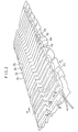
- Fig. 2 shows the air mat with its first unit 2 of air cells (hereinafter referred to as first air cell unit 2) inflated while the second unit 3 of the air cells (hereinafter referred to as second air cell unit 3) deflated.
- first air cell unit 2 first unit 2 of air cells
- second air cell unit 3 second unit 3 of the air cells
- the first and the second air cell unit 2 and 3, respectively, of the air mat 1 are made of flexible airtight sheets in the form of elongate sealable bags.
- the air cells of the first air cell unit 2 are connected at the right ends thereof (referred to as communication ends 4) with the adjacent ones, which are in turn connected to an air pump (not shown) via an air inlet/outlet tube 5.
- the air cells of the second air cell unit 3 are connected at their left communication ends 6 with their neighbors, which are also in turn connected to the air pump via an air inlet/outlet tube 7.
- the air cells of the first and the second air cell unit 2 and 3, respectively, are arranged to alternate in the direction of the mat length and are alternately inflated and deflated at a given period of time.
- the air mat is adapted to maintain the air pressure in the air cells at a level which is about one half the pressure of the fully inflated air cells even when they are deflated, as shown in Fig. 2, so that the pressure difference between the inflated and the deflated air cells would not give the patient an uncomfortable feeling.
- the air mat pressure may be arbitrarily regulated to harden or soften the air mat on the request of the patient.
- Each of the first and the second air cell unit 2 and 3, respectively, are provided with right air cells 2a and 3a, respectively, and left air cells 2b and 3b, respectively, and central bent sections 2c and 3c, respectively, which are each connected between a pair of the right and left air cells of a given air cell unit.
- bent sections 2c and 3c connect smoothly, but relatively offset positions in the longitudinal direction, the associated pairs of the right and the left air cells 2a and 2b, respectively, of the first air cell unit 2, and the right and the left air cells 3a and 3b, respectively, of the second air cell unit 3.
- the frontal air cell 2d belonging to the first air cell unit 2 and the rear most air cell 3d belonging to the second air cell unit 3 have one half the length of the rest of the air cells and aligned to the terminal air cells of the other unit so that a line of air cells is formed across the entire width at the frontal end as well as the rear end of the air mat, leaving no abrupt step at both ends.
- the widths of the right and the left air cells 2a, 3a, 2b and 3b of the first and the second air cell units 2 and 3, respectively, are of the same width W of the central bent sections as measured along the center line P1 of the air mat.
- the width Wc of the bent sections as measured in the direction normal thereto is smaller than W. That is, the bent sections have smaller circular diameter than the right and the left air cells 2a, 3a, 2b and 3b.
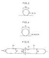
- the difference in width between the bent sections 2c and 3c and the right and the left air cells 2a, 3a, 2b and 3b is 2h as shown in Figs. 3 - 5.
- the right air cells 2a and 3a are connected smoothly with the associated left air cells 2b and 3b by the respective bent sections 2c and 3c.
- the width W of a completely deflated air cell in the range from 5 to 20 cm
- the width Wa of the bent sections 2c and 3c in the ranges from 5 to 30 cm.
- the choice of the above mentioned range for the width of the air cells is desirable in distributing the inflated and deflated air cells at proper intervals to appropriately support the body of a patient.
- the range of the width for the bent sections is chosen to ensure a sufficient width of the bent sections for widely and uniformly supporting areas including the backbone of the patient.
- the right air cells 2a of the first air cell unit 2 and the left air cells 3b of the second air cell unit 3 are arranged so that the corresponding right and left air cells are linearly aligned, as shown in Fig. 2, and that the right air cells 3a of the second air cell unit 2 and the left air cells 2b of the first air cell unit 2 are arranged so that the corresponding right and left air cells are linearly aligned in the same manner.
- the center lines P2 of the completely deflated right and the left air cells 2a and 3b, respectively, are relatively offset in the longitudinal direction on the opposite sides of the center line P1, as shown in Fig. 1.
- the air mat 1 shrinks in the longitudinal direction (in the direction parallel to the center line P1) and the center line P2 of the air cells 2a and 3b are aligned with each other when the air mat 1 is inflated.
- the two units alternately support different portions of the patient in good balance.
- the offset angle ⁇ of the bent sections with respect to the direction of the mat width preferably ranges from 10 to 70 degrees.
- the dimension Wa of the bent sections in the direction of the mat width is preferably in the range from 5 to 30 cm, and the width W of the light and the left air cells 2a, 3a, 2b and 3b, respectively, are in the range from 5 to 20 cm, as described previously.
- the bent section gets much bent in the direction of the mat width and making the area of bent section relative to the entire supporting area of the mat becomes very small, thereby providing only a weak supporting force to the patient. This force is undesirably unbalanced with the forces given by the right and the left air cells connected therewith.
- the angle ⁇ is made smaller than 10 degrees, the pressure difference between the bent section and the associated right and left air cells 2 and 3 becomes very small and can excessively oppress the backbone area of the patient. Further, if the angle ⁇ is less than 10 degrees, the offset in the longitudinal direction of the right and the left air cells 2 and 3, respectively, becomes too small to maintain well balanced supporting forces for the patient, as discussed in connection with a conventional air mat.
- bent sections 2c and 3c and the right and the left air cells are dimensioned within the ranges as described above, so that, when they are inflated the right and the left air cells 2a, 3a, 2b and 3b are substantially aligned in the direction of the mat width and maintain adequate intervals to provide an massaging effect to the patient by the abutting sections.
- the air mat can be fabricated from duplicated impervious (i.e. airtight) sheets by bonding them together along the boundary lines 8 that defines the intended air cells, using a high frequency welding technique for example.
- Each of the sheets can be obtained by laminating a thermoplastic resin such as polyvynilchloride (PVC) on one or both sides of a woven nylon fabric for example.
- PVC polyvynilchloride
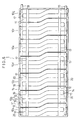
- FIG. 6 shows another example of an air mat 1 according to the invention, in which the air mat 1 consists of a multiplicity of (for example, seven) separate air mats 10a-10g.
- the air mat 1 consists of a multiplicity of (for example, seven) separate air mats 10a-10g.
- Each of the separate air mats 10a-10g has basically the same structure as the first example described above.
- Each of the separate air mats 10b-10f comprises a first and a second air cell units 11 and 12, respectively, each unit having two air cells in such way that the air cells of the two units are interleaved in the longitudinal direction of the air mat.
- the two air cells of the unit 11 are connected with each other at the communication ends 13 thereof as shown in Fig. 6, while the two air cells of the unit 12 are connected for communication at the communication ends 14 thereof.
- each of the terminal air mats 10a and 10g has an air cell (which is a first air cell 11 in the case of the separate air mat 10a and a second air cell 12 in the case of the separate air mat 10g), plus an additional air cell unit including 3/2 air cells (which unit is a second air cell unit 12 in the case of the separate air mat 10a, and a first air cell unit 11 in the case of the separate air mat 10g).
- the separate air mats 10b-10f are provided with two units each having two air cells for the following reason.
- the air cell units 11 and 12 are alternately inflated and deflated, they must have an even number of air cells.
- the air cell units could have 2, 4, 6, or 8 air cells for example.
- optimizing such design factors as convenience of the air mat, an overall dimensional limitation, and exchangeability of the separate air mats, use of four air cells for one separate air mat is the best choice.
- each air cell unit is made of a single air cell, the air cell can be deformed independently, the deformation being appreciable in the central region of the air mat, so that the deviation of the body of the patient becomes significant. This makes the patient uncomfortable on the air mat. It has been known that this is also the case when the air cell unit consists of two air cells.
- the inventors have experimentally shown that an air cell unit having 6 air cells exhibits the same effect as the air cell unit having four air cells.
- the separate air mats 10a-10g are fabricated by welding two sheets in the same process as in the case of the first example. They are adapted to be removably fastened to a base fabric 15 underlying the mats 10a-10g by means of fasteners.
- the fasteners can be hooks or buttons 16 as shown in Fig. 6.
- the base fabric 15 can be a waterproofed antislipping nylon fabric.
- the base fabric 15 is provided with a pair of cloth bands 17 for preventing the air mats to be displaced from their normal positions while supporting a patient.
- air inlet/outlet tubes 18 and 19 are provided between the separate air mats 10a-10g and the base fabric 15 which are connected to the respective air mats at the opposite communication ends 13 and 14 of the air mats.
- the air inlet/outlet tubes 18 and 19 are provided with joints 20 made of a plastic such as PVC for connecting the air inlet/ outlet tubes with the communication ends 13 and 14 of the first and the second air cell units 11 and 12, respectively.
- Each of the joints 20 has a male and a female joints 21 and 22, respectively, each having four protrusions 23 and 24, respectively, as shown in Figs. 7 and 8.
- the male joint 21 is provided with a rubber O-ring 25 inserted in a bottom section of the male joint 21.
- the male joints 21 are connected to the air inlet/outlet tube 18 and 19, while the female joints 22 are connect to the communication ends 13 and 14 as shown in Fig. 8, using a known bonding technique such as high frequency welding.
- the male and female joints 21 and 22, respectively, can be firmly coupled together by forcing the female joint 22 onto the male joint 21 and rotating the female joint 22 through an angle of about 45 degrees until the protrusions 24 of the female joint are seated under the protrusions 23 of the male joint 21.
- each of the separate air mats 10a-10g may by removed from the base fabric 15 independently, so that if one of them is broken or stained, it can be replaced.
- the dimensions of the fully deflated first and the second air cell units 2 and 3, respectively, not including the communication ends 4 and 6, are 80 cm in length as measured in the direction of the mat width and 265 cm in width as measured along the centerline P1.
- the dimensions of the right and the left air cells 2a, 3a, 2b and 3b are 34.5 cm in length and 10 cm in width W.
- the dimensions of the bent sections 2c and 3c having an offset angle of 30 degrees are 11 cm in length and 8.66 cm in width Wc.
- the inflated air cells 2a, 3a, 2b and 3b are aligned in the direction of the mat width.
- the air pressure inside the inflated air cells in use is in the range from 26 700 to 107 000 Pa.
- the air pressure drops to about 1/2 when the air cells are deflated.
- the bent sections 2c and 3c as well as the right and the left air cells of the air cell units 2 and 3 have round cross sections as shown in Figs. 3 and 4, when they are inflated.
- the bent sections 2c and 3c have a smaller radius than the air cells 2a, 3a, 2b and 3b by has described previously.
- the first and the second air cell units 2 and 3 are inflated alternately.
- the corresponding left air cells 3b adjacent to the right air cells are inflated.
- the air mat has been described for a case where the first and the second air cell units which are alternately inflated and deflated. It would be understood, however, the first and the second air cell units may be simultaneously inflated.
- the first and the second air cell units may be connected with each other by a single tube without distinguishing them, so that they can be inflated and deflated together.
- an air mat is realized in which the right and the left air cells are inflated high while keeping all the central bent sections low by inflating all the air cells at a uniform pressure.
- the right and the left air cells may support the right and the left portions of the patient, and the bent sections may support his protruding backbone without any excessive oppression thereof, thereby providing for a well balanced support for the entire portions of the patient.
- each of the air cells has a generally linear configuration in the form of an hourglass shape or of two truncated cones joined together at their truncated ends, so that the air cell has a longitudinal V-shaped cross section at the center thereof.
- an air mat in accordance with the invention has a central lower portion consisting of closely spaced neighboring bent sections of air cells, thereby overcoming the above mentioned disadvantages pertinent to the known air mat.
Landscapes
- Health & Medical Sciences (AREA)
- Nursing (AREA)
- Life Sciences & Earth Sciences (AREA)
- Animal Behavior & Ethology (AREA)
- General Health & Medical Sciences (AREA)
- Public Health (AREA)
- Veterinary Medicine (AREA)
- Invalid Beds And Related Equipment (AREA)
- Mattresses And Other Support Structures For Chairs And Beds (AREA)
Description
- The present invention relates generally to an air mat, and more particularly to an air mat suitable for preventing decubitus that can easily afflict a bedridden patient.
- Decubitus is a symptom that can arise mainly in the tissues in bonny areas of a bedridden patient, for example, caused by necrosis due to local oppressions of the tissue and resulting obstruction of blood circulation therein while he or she has been in bed for a long time.
- If the patient does not suffer from such decubitus, he or she often feels pains or unpleasant oppression at the bonny areas. In order to relieve such pains and unpleasant oppression, an air mat has been developed and widely used which consists of a multiplicity of interleaved elongate air cells arranged in parallel in the direction of the width of the air mat (hereinafter referred to as the transverse direction or the direction of the mat width). These air cells are divided into two groups such that the two groups of the air cells are inflated with air and deflated alternately at a given period of time.
- We also refer to the longitudinal direction of the mat as the direction of the mat length; and the length and the width of air cells as the cell length and the cell width, respectively.
- Unfortunately, such known air mat as mentioned above abuts symmetrically on the back of the patient at his right and left sides, since air cells extend linearly in the transverse direction of the mat.
- It is known that given stimuli at bilaterally symmetrical positions, a patient feels the positions of stimuli clearly since a nerve net of a human being has a generally bilateral symmetry.
- Further, the patient often feels inflation and deflation operations of the air mat not only monotonous but also uncomfortable when the air mat is partially deflated because then his/her body tends to sink due to his/her weight.
- To solve such problems as mentioned above, an air mat has been disclosed in which each air cells is divided lengthwise into a right and a left sections communicating with each other at the center thereof, and arranged in such a way that the right and the left sections are offset to each other in the longitudinal direction of the air mat.
- Having this structure, the air mat can support the body of the patient stretched out on the air mat, with a central groove formed along the connecting sections of the right and the left section fitting better to the patient's backbone with a less pressure.
- In this type of air mat, however, the central connection sections extends along the length of the air mat and the central connection sections make a rather deep and steep longitudinal V-shaped groove as the right and the left air cells are fully inflated. Consequently, the area of the air mat supporting the backbone is reduced to a degree that part of the groove sometimes fails to abuts on the backbone. This can result in an extreme decrease in the supporting force of the air mat for the backbone.
- The decrease in the supporting force acting on the backbone implies a corresponding increase in the supporting force acting on its neighboring areas, thereby failing to provide the patient with loosing a comfortable uniform distribution of the supporting force on the back.
- The invention is directed to overcome these problems by providing an improved air mat which can support in good balance the backbone section as well as its neighboring area of the patient, so that the patient may rest on the air mat in comfort.
- From US-A-3,199,124 an air mat according to the preamble part of the main claim is known.
- The above-mentioned problems of the conventional air mat are overcome by the features of the main claim.
- Advantageous embodiments are mentioned in the sub claims.
-
- Fig. 1 is a plan view of a first air mat embodying the invention.
- Fig. 2 is a perspective view of the air mat of Fig. 1 in use.
- Fig. 3 is a cross section of air mat taken along line III-III of Fig. 2.
- Fig. 4 is a cross section of air mat taken along line IV-IV of Fig. 2.
- Fig. 5 is a cross section of air mat taken along line V-V of Fig. 2.
- Fig. 6 is a plan view of a second air mat embodying the invention comprising a multiplicity of separate air mats.
- Fig. 7 is an exploded perspective view of a fastener for fastening the separate air mats shown in Fig. 6.
- Fig. 8 is a cross section of the fastener, showing the structure thereof when it is used to lock a separate air mat in position.
- The invention will now be described in detail by way of examples with reference to accompanying drawings.
- Referring now to Fig. 1, there is shown in plan view of an
air mat 1 embodying the invention which is completely deflated. Fig. 2 shows the air mat with itsfirst unit 2 of air cells (hereinafter referred to as first air cell unit 2) inflated while thesecond unit 3 of the air cells (hereinafter referred to as second air cell unit 3) deflated. - The first and the second
air cell unit air mat 1 are made of flexible airtight sheets in the form of elongate sealable bags. - The air cells of the first
air cell unit 2 are connected at the right ends thereof (referred to as communication ends 4) with the adjacent ones, which are in turn connected to an air pump (not shown) via an air inlet/outlet tube 5. Similarly, the air cells of the secondair cell unit 3 are connected at their left communication ends 6 with their neighbors, which are also in turn connected to the air pump via an air inlet/outlet tube 7. - The air cells of the first and the second
air cell unit - The air mat is adapted to maintain the air pressure in the air cells at a level which is about one half the pressure of the fully inflated air cells even when they are deflated, as shown in Fig. 2, so that the pressure difference between the inflated and the deflated air cells would not give the patient an uncomfortable feeling. In addition, the air mat pressure may be arbitrarily regulated to harden or soften the air mat on the request of the patient.
- Each of the first and the second
air cell unit right air cells left air cells central bent sections - The
bent sections left air cells air cell unit 2, and the right and theleft air cells air cell unit 3. - As shown in Fig. 1, the
frontal air cell 2d belonging to the firstair cell unit 2 and the rearmost air cell 3d belonging to the secondair cell unit 3 have one half the length of the rest of the air cells and aligned to the terminal air cells of the other unit so that a line of air cells is formed across the entire width at the frontal end as well as the rear end of the air mat, leaving no abrupt step at both ends. - The widths of the right and the
left air cells air cell units - Consequently, the width Wc of the bent sections as measured in the direction normal thereto is smaller than W. That is, the bent sections have smaller circular diameter than the right and the
left air cells - The difference in width between the
bent sections left air cells right air cells left air cells respective bent sections - In the example shown herein, it is preferable to choose the width W of a completely deflated air cell in the range from 5 to 20 cm, and the width Wa of the
bent sections - The choice of the above mentioned range for the width of the air cells is desirable in distributing the inflated and deflated air cells at proper intervals to appropriately support the body of a patient.
- The range of the width for the bent sections, 5 - 30 cm, is chosen to ensure a sufficient width of the bent sections for widely and uniformly supporting areas including the backbone of the patient.
- It is preferable that the
right air cells 2a of the firstair cell unit 2 and theleft air cells 3b of the secondair cell unit 3 are arranged so that the corresponding right and left air cells are linearly aligned, as shown in Fig. 2, and that theright air cells 3a of the secondair cell unit 2 and theleft air cells 2b of the firstair cell unit 2 are arranged so that the corresponding right and left air cells are linearly aligned in the same manner. - In order to ensure such skewed arrangement of the air cells as described above, the center lines P2 of the completely deflated right and the
left air cells - In this arrangement, the
air mat 1 shrinks in the longitudinal direction (in the direction parallel to the center line P1) and the center line P2 of theair cells air mat 1 is inflated. As the first and thesecond air cells - The offset angle θ of the bent sections with respect to the direction of the mat width preferably ranges from 10 to 70 degrees. The dimension Wa of the bent sections in the direction of the mat width is preferably in the range from 5 to 30 cm, and the width W of the light and the
left air cells - It is noted that if the angle θ is larger than 70 degrees, the bent section gets much bent in the direction of the mat width and making the area of bent section relative to the entire supporting area of the mat becomes very small, thereby providing only a weak supporting force to the patient. This force is undesirably unbalanced with the forces given by the right and the left air cells connected therewith.
- On the other hand, if the angle θ is made smaller than 10 degrees, the pressure difference between the bent section and the associated right and
left air cells left air cells - Thus, the
bent sections left air cells - The air mat can be fabricated from duplicated impervious (i.e. airtight) sheets by bonding them together along the
boundary lines 8 that defines the intended air cells, using a high frequency welding technique for example. Each of the sheets can be obtained by laminating a thermoplastic resin such as polyvynilchloride (PVC) on one or both sides of a woven nylon fabric for example. - It will be apparent that when PVC laminated fabrics are used for this purpose the laminated surfaces are bonded.
- Fig. 6 shows another example of an
air mat 1 according to the invention, in which theair mat 1 consists of a multiplicity of (for example, seven) separate air mats 10a-10g. Each of the separate air mats 10a-10g has basically the same structure as the first example described above. - Each of the
separate air mats 10b-10f, except for the terminal ones, comprises a first and a secondair cell units unit 11 are connected with each other at the communication ends 13 thereof as shown in Fig. 6, while the two air cells of theunit 12 are connected for communication at the communication ends 14 thereof. - It would be noted that in order to complete the linear arrangements of the terminal air cells at the
terminal mats 10a and 10g of theair mat 1, each of theterminal air mats 10a and 10g has an air cell (which is afirst air cell 11 in the case of the separate air mat 10a and asecond air cell 12 in the case of theseparate air mat 10g), plus an additional air cell unit including 3/2 air cells (which unit is a secondair cell unit 12 in the case of the separate air mat 10a, and a firstair cell unit 11 in the case of theseparate air mat 10g). - The
separate air mats 10b-10f are provided with two units each having two air cells for the following reason. - Since the first and the second
air cell units - It should be noted that if each air cell unit is made of a single air cell, the air cell can be deformed independently, the deformation being appreciable in the central region of the air mat, so that the deviation of the body of the patient becomes significant. This makes the patient uncomfortable on the air mat. It has been known that this is also the case when the air cell unit consists of two air cells.
- As opposed to this, in the case where four air cells are united in one unit, if the weight of the patient concentrates on one of the air cells, a deflated one say, so that the body is acted upon by a force deviating the body in one direction (to the deflated air cell in the example above), the neighboring air cells communicating with the very one air cell is inflated and not deformed greatly, so that the neighboring air cells will suppress the deviation of the body. Such unified air cells may be obtained by bonding two sheets, as described previously.
- The inventors have experimentally shown that an air cell unit having 6 air cells exhibits the same effect as the air cell unit having four air cells.
- The separate air mats 10a-10g are fabricated by welding two sheets in the same process as in the case of the first example. They are adapted to be removably fastened to a
base fabric 15 underlying the mats 10a-10g by means of fasteners. - The fasteners can be hooks or
buttons 16 as shown in Fig. 6. Thebase fabric 15 can be a waterproofed antislipping nylon fabric. - The
base fabric 15 is provided with a pair ofcloth bands 17 for preventing the air mats to be displaced from their normal positions while supporting a patient. - Provided between the separate air mats 10a-10g and the
base fabric 15 are air inlet/outlet tubes - The air inlet/
outlet tubes joints 20 made of a plastic such as PVC for connecting the air inlet/ outlet tubes with the communication ends 13 and 14 of the first and the secondair cell units - Each of the
joints 20 has a male and afemale joints protrusions - The male joint 21 is provided with a rubber O-
ring 25 inserted in a bottom section of the male joint 21. The male joints 21 are connected to the air inlet/outlet tube female joints 22 are connect to the communication ends 13 and 14 as shown in Fig. 8, using a known bonding technique such as high frequency welding. - The male and
female joints protrusions 24 of the female joint are seated under theprotrusions 23 of the male joint 21. - Under the coupled condition, the female joint 22 abuts on the resilient rubber O-
ring 25 fitted on the male joint 21 to seal the joint 20 as shown in Fig. 8. - With this arrangement, each of the separate air mats 10a-10g may by removed from the
base fabric 15 independently, so that if one of them is broken or stained, it can be replaced. - By preparing extra separate air mats, replacement of a separate air mat can be done very easily and promptly, without inconvenient replacement of the entire air mat, thereby rendering the air mat more usable.
- As an example, the dimensions of the fully deflated first and the second
air cell units - The dimensions of the right and the
left air cells bent sections - When the air cells are inflated, the width W becomes 6.36 cm; Wc, 5.51 cm. The difference h in radius between the bent section and the right and the left air cells becomes 0.85 cm.
- The
inflated air cells - The air pressure inside the inflated air cells in use is in the range from 26 700 to 107 000 Pa. The air pressure drops to about 1/2 when the air cells are deflated.
- The
bent sections air cell units bent sections air cells - In this arrangement, when a patient lies on the
air mat 1, the first and the secondair cell units right air cells 2a are deflated, the correspondingleft air cells 3b adjacent to the right air cells are inflated. - Consequently, portions of the body of the patient not supported directly by the deflated air cells of one air cell unit are supported indirectly by the inflated air cells of the other air cell unit. The inventors have confirmed that this arrangement may prevent appreciable vertical displacements of the patient's body through inflation and deflation operations and hence enhance stability of the patient.
- It has been also confirmed that the supporting forces given by the
bent sections left cells - In the example shown hereinabove, the air mat has been described for a case where the first and the second air cell units which are alternately inflated and deflated. It would be understood, however, the first and the second air cell units may be simultaneously inflated.
- When the air mat is to be used in this manner, the first and the second air cell units may be connected with each other by a single tube without distinguishing them, so that they can be inflated and deflated together.
- Thus, in this case, an air mat is realized in which the right and the left air cells are inflated high while keeping all the central bent sections low by inflating all the air cells at a uniform pressure.
- Then the right and the left air cells may support the right and the left portions of the patient, and the bent sections may support his protruding backbone without any excessive oppression thereof, thereby providing for a well balanced support for the entire portions of the patient.
- It should be appreciated that, since the central sections of the air mat is lowered, the patient has a less chance to roll over the air mat to the right or the left and falls off the air mat.
- An air mat has been known which has a lower central section in order to stabilize the body of a patient. For example, each of the air cells has a generally linear configuration in the form of an hourglass shape or of two truncated cones joined together at their truncated ends, so that the air cell has a longitudinal V-shaped cross section at the center thereof.
- However, when a multiplicity of such linear air cells are arranged in parallel with each other, their spacing is limited by the large diameter of the opposite ends of the air cells, so that the central narrow sections are largely spaced apart from the adjacent ones, providing only an uncomfortable support for the patient. That is, they are not capable of providing a comfortable support required for a practical and useful air mat.
- As opposed to such known air mats, an air mat in accordance with the invention has a central lower portion consisting of closely spaced neighboring bent sections of air cells, thereby overcoming the above mentioned disadvantages pertinent to the known air mat.
Claims (6)
- An air mat having a longitudinal and a transverse direction and including a first (2) and a second (3) air cell units, said units respectively including a multiplicity of elongate flexible air cells arranged in the transverse direction of said air mat, with the air cells of one air cell unit interleaved by the air cells of the other air cell unit, said two air cell units adapted to be inflated and deflated alternately, said air mat being characterized in that:each of said first and second air cell units includes right (2a, 3a) and left (2b, 3b) air cells; andbent sections (2c, 3c) connected between said right and left air cells, and located at the center line (P1) along the length of said air mat, whereinsaid right and left air cells are offset each other in the longitudinal direction of said air mat by said bent sections; andsaid first and second air cell units are arranged such that, when said first or second air cell unit is inflated, the right air cells of said inflated air cell unit (2 or 3) have respective centerlines (P2) along the transverse direction of said air mat aligned with the centerlines of corresponding left air cells of the deflated air cell unit (3 or 2).
- The air mat according to claim 1, wherein said right and left air cells of said first and second air cell units (2, 3) and said bent sections (2c, 3c) have the same cell width as measured in the direction of the mat length.
- The air mat according to claim 1 or 2, wherein
the offset angle of said bent sections (2c, 3c) is in the range from 10 to 70 degrees;
the width of said right and left air cells (2a, 3a, 2b, 3b) as measured in the direction of the mat length is in the range from 5 to 20 cm; and
the dimension of said bent section (2c, 3c) as measured in the direction of mat width is in the range from 5 to 30 cm. - The air mat according to claim 1, wherein said air mat is made of two airtight fabric sheets bonded along the boundaries of intended air cells of said first and second air cell units, each of said sheets laminated with a plastic on at least one side thereof.
- The air mat according to claim 1, wherein
said air mat comprises a multiplicity of separate air mats which are adapted to be removably mounted on a base fabric by means of fasteners (20); and
each of said first and second air cell units of said separate air mat is provided with an air inlet/outlet tube (7, 8, 18, 19) disposed between said separate air mat and said base fabric. - The air mat according to claim 4 or 5, wherein
each of said separate air mats comprises a first and a second units of two air cells;
said air cells of said first unit are connected at one ends thereof and at one end of said air mat; and
said air cells of said second unit are connected at one ends thereof and at the opposite end of said air mat.
Applications Claiming Priority (6)
| Application Number | Priority Date | Filing Date | Title |
|---|---|---|---|
| JP15417998 | 1998-06-03 | ||
| JP15417998 | 1998-06-03 | ||
| JP20894698 | 1998-07-24 | ||
| JP20894698 | 1998-07-24 | ||
| JP12913799A JP3290159B2 (en) | 1998-06-03 | 1999-05-10 | Air mat |
| JP12913799 | 1999-05-10 |
Publications (3)
| Publication Number | Publication Date |
|---|---|
| EP0962210A2 EP0962210A2 (en) | 1999-12-08 |
| EP0962210A3 EP0962210A3 (en) | 2000-05-03 |
| EP0962210B1 true EP0962210B1 (en) | 2006-01-18 |
Family
ID=27315883
Family Applications (1)
| Application Number | Title | Priority Date | Filing Date |
|---|---|---|---|
| EP99110587A Expired - Lifetime EP0962210B1 (en) | 1998-06-03 | 1999-06-01 | Air mat |
Country Status (7)
| Country | Link |
|---|---|
| US (1) | US6151740A (en) |
| EP (1) | EP0962210B1 (en) |
| JP (1) | JP3290159B2 (en) |
| AU (1) | AU749108B2 (en) |
| CA (1) | CA2273623C (en) |
| DE (1) | DE69929484T2 (en) |
| DK (1) | DK0962210T3 (en) |
Families Citing this family (22)
| Publication number | Priority date | Publication date | Assignee | Title |
|---|---|---|---|---|
| USD474061S1 (en) | 1998-08-24 | 2003-05-06 | The Nautilus Group, Inc. | Air mattress |
| USD471051S1 (en) | 1998-08-24 | 2003-03-04 | The Nautilus Group, Inc. | Air mattress |
| US6665893B2 (en) * | 2001-04-06 | 2003-12-23 | L & P Property Management Company | Sofa sleeper with integral air mattress and valve |
| KR100431662B1 (en) * | 2001-10-16 | 2004-05-17 | 현대메디칼 주식회사 | Method of manufacturing an abdominal belt and mould |
| US6643875B2 (en) | 2001-11-14 | 2003-11-11 | Aero International Products, Inc. | Inflatable mattress topper |
| WO2006006216A1 (en) * | 2004-07-09 | 2006-01-19 | Ngc Corporation | Buffer mat for gymnastics |
| DE602006006417D1 (en) * | 2005-02-14 | 2009-06-04 | Pegasus Ltd | CHANGE OF PRESSURE MATTRESS |
| CA2620256A1 (en) * | 2005-08-25 | 2007-03-01 | Molten Corporation | Air mattress |
| FR2917278A1 (en) | 2007-06-18 | 2008-12-19 | Hill Rom Ind S A Sa | MATTRESS-TYPE SUPPORT DEVICE HAVING A HETEROGENEUS INFLATABLE STRUCTURE |
| FR2922439B1 (en) | 2007-10-18 | 2010-12-10 | Hill Rom Ind Sa | METHOD FOR ALTERNATE INFLATION OF AN INFLATABLE CELL SUPPORT DEVICE AND DEVICE FOR IMPLEMENTING IT |
| US8127386B2 (en) * | 2007-12-03 | 2012-03-06 | Molten Corporation | Air mattress |
| FR2924927B1 (en) * | 2007-12-14 | 2009-12-25 | Thaddee Mulliez | ANTI-ESCARTER INFLATABLE MATTRESS |
| GB2458892B (en) * | 2008-03-31 | 2012-11-28 | Talley Group Ltd | Temperature controlled mattress system |
| US20110252571A1 (en) * | 2010-04-15 | 2011-10-20 | Liu Tsung Hsi | Multiple air passages applied to air mattress |
| US8863338B2 (en) | 2010-06-02 | 2014-10-21 | Touchsensor Technologies, Llc | Therapeutic support device allowing capillary blood flow |
| ES2913287T3 (en) | 2010-10-05 | 2022-06-01 | Dabir Surfaces Inc | Apparatus, system and method of support |
| DE202014001059U1 (en) * | 2014-02-08 | 2015-08-06 | Ernst Heinrich | Massage topper with heat function for mattresses and lying surfaces |
| DE202014001062U1 (en) * | 2014-02-09 | 2015-05-12 | Ernst Heinrich | Zones - air massage mattress with heat function |
| CN105266995A (en) * | 2014-07-23 | 2016-01-27 | 上海尔玛医疗器械有限公司 | Fluctuant mattress and wave-shaped massage air cushion of same |
| US10531996B2 (en) | 2015-11-06 | 2020-01-14 | Andrei Cernasov | Supporting surface with programmable supports and method to reduce pressure on selected areas of a body |
| FR3109908B1 (en) * | 2020-05-07 | 2023-07-07 | Paris Sciences Lettres Quartier Latin | Pneumatic structure and associated manufacturing method |
| KR102791083B1 (en) * | 2024-08-19 | 2025-04-07 | 주식회사 제이엠세이프티 | Shift support mattress and control method thereof |
Family Cites Families (10)
| Publication number | Priority date | Publication date | Assignee | Title |
|---|---|---|---|---|
| US3199124A (en) * | 1963-03-29 | 1965-08-10 | R D Grant Company | Air mattress |
| GB1286197A (en) * | 1970-03-13 | 1972-08-23 | Ronald James Peter Evans | Improvements in or relating to alternating pressure pads for bed patients |
| US4267611A (en) * | 1979-03-08 | 1981-05-19 | Arnold Agulnick | Inflatable massaging and cooling mattress |
| US4347633A (en) * | 1980-07-22 | 1982-09-07 | American Hospital Supply Corporation | Patient treating mattress |
| GB2090734B (en) * | 1980-10-27 | 1985-03-13 | Olivelark Ltd | Improvements in alternating pressure beds |
| US5103518A (en) * | 1989-08-01 | 1992-04-14 | Bio Clinic Corporation | Alternating pressure pad |
| US5243723A (en) * | 1992-03-23 | 1993-09-14 | Innovative Medical Systems, Inc. | Multi-chambered sequentially pressurized air mattress with four layers |
| US5437068A (en) * | 1992-06-10 | 1995-08-01 | Intex Recreation Corp. | Body-conforming, multi-foldable, inflatable mattress having phase-shifted sinusoidal seals |
| US5701622A (en) * | 1996-01-16 | 1997-12-30 | Sentech Medical Systems, Inc. | Pulsating operating table cushion |
| US5901393A (en) * | 1996-05-31 | 1999-05-11 | Gaymar Industries Inc. | Alternating pressure support pad |
-
1999
- 1999-05-10 JP JP12913799A patent/JP3290159B2/en not_active Expired - Lifetime
- 1999-06-01 DE DE69929484T patent/DE69929484T2/en not_active Expired - Lifetime
- 1999-06-01 DK DK99110587T patent/DK0962210T3/en active
- 1999-06-01 US US09/323,043 patent/US6151740A/en not_active Expired - Lifetime
- 1999-06-01 CA CA002273623A patent/CA2273623C/en not_active Expired - Fee Related
- 1999-06-01 EP EP99110587A patent/EP0962210B1/en not_active Expired - Lifetime
- 1999-06-03 AU AU33141/99A patent/AU749108B2/en not_active Ceased
Also Published As
| Publication number | Publication date |
|---|---|
| CA2273623C (en) | 2007-02-06 |
| AU3314199A (en) | 1999-12-16 |
| DE69929484D1 (en) | 2006-04-06 |
| EP0962210A2 (en) | 1999-12-08 |
| DE69929484T2 (en) | 2006-09-07 |
| AU749108B2 (en) | 2002-06-20 |
| US6151740A (en) | 2000-11-28 |
| EP0962210A3 (en) | 2000-05-03 |
| JP3290159B2 (en) | 2002-06-10 |
| DK0962210T3 (en) | 2006-05-29 |
| JP2000093467A (en) | 2000-04-04 |
| CA2273623A1 (en) | 1999-12-03 |
Similar Documents
| Publication | Publication Date | Title |
|---|---|---|
| CA2273623C (en) | Air mat | |
| US5109561A (en) | Alternating pressure pad | |
| US5619764A (en) | Mattress for decubitus prophylaxis | |
| US4472847A (en) | Patient treating mattress | |
| CA1163884A (en) | Patient treating mattress | |
| US6701556B2 (en) | Mattress or cushion structure | |
| US5243723A (en) | Multi-chambered sequentially pressurized air mattress with four layers | |
| US5918336A (en) | Structure of alternately inflated/deflated air bed | |
| CA2360231C (en) | Air mattress | |
| US4698864A (en) | Cellular cushion | |
| US7107640B2 (en) | Inflatable support | |
| CN1209733A (en) | Alternating pad | |
| US20110203053A1 (en) | Inflatable cell for anti-eschar mattresses | |
| US4914762A (en) | Inflatable cushion | |
| US5621934A (en) | Mattress | |
| JPH08164167A (en) | Air mat for medical treatment | |
| EP1874250B1 (en) | An inflatatable component for an alternating pressure mattress | |
| WO1997012531A1 (en) | Pressure ulcer-relieving mattress | |
| JPH09224983A (en) | Air mat device | |
| JPH0585183B2 (en) | ||
| KR102752185B1 (en) | A waist pillow | |
| EP1031338B1 (en) | Alternating pressure pad for wheel chairs and mattresses | |
| JPH08206159A (en) | Air mat | |
| CA1163885A (en) | Patient treating mattress | |
| KR20210032814A (en) | Active body pressure dispersion-typed air cell mattress |
Legal Events
| Date | Code | Title | Description |
|---|---|---|---|
| PUAI | Public reference made under article 153(3) epc to a published international application that has entered the european phase |
Free format text: ORIGINAL CODE: 0009012 |
|
| AK | Designated contracting states |
Kind code of ref document: A2 Designated state(s): DE DK FR GB NL |
|
| AX | Request for extension of the european patent |
Free format text: AL;LT;LV;MK;RO;SI |
|
| PUAL | Search report despatched |
Free format text: ORIGINAL CODE: 0009013 |
|
| AK | Designated contracting states |
Kind code of ref document: A3 Designated state(s): AT BE CH CY DE DK ES FI FR GB GR IE IT LI LU MC NL PT SE |
|
| AX | Request for extension of the european patent |
Free format text: AL;LT;LV;MK;RO;SI |
|
| 17P | Request for examination filed |
Effective date: 20000630 |
|
| AKX | Designation fees paid |
Free format text: DE DK FR GB NL |
|
| 17Q | First examination report despatched |
Effective date: 20030210 |
|
| GRAP | Despatch of communication of intention to grant a patent |
Free format text: ORIGINAL CODE: EPIDOSNIGR1 |
|
| GRAS | Grant fee paid |
Free format text: ORIGINAL CODE: EPIDOSNIGR3 |
|
| GRAA | (expected) grant |
Free format text: ORIGINAL CODE: 0009210 |
|
| AK | Designated contracting states |
Kind code of ref document: B1 Designated state(s): DE DK FR GB NL |
|
| RAP1 | Party data changed (applicant data changed or rights of an application transferred) |
Owner name: MOLTEN CORPORATION |
|
| REG | Reference to a national code |
Ref country code: GB Ref legal event code: FG4D |
|
| REF | Corresponds to: |
Ref document number: 69929484 Country of ref document: DE Date of ref document: 20060406 Kind code of ref document: P |
|
| ET | Fr: translation filed | ||
| PLBE | No opposition filed within time limit |
Free format text: ORIGINAL CODE: 0009261 |
|
| STAA | Information on the status of an ep patent application or granted ep patent |
Free format text: STATUS: NO OPPOSITION FILED WITHIN TIME LIMIT |
|
| 26N | No opposition filed |
Effective date: 20061019 |
|
| PGFP | Annual fee paid to national office [announced via postgrant information from national office to epo] |
Ref country code: FR Payment date: 20100706 Year of fee payment: 12 Ref country code: DK Payment date: 20100610 Year of fee payment: 12 |
|
| PGFP | Annual fee paid to national office [announced via postgrant information from national office to epo] |
Ref country code: NL Payment date: 20100614 Year of fee payment: 12 |
|
| PGFP | Annual fee paid to national office [announced via postgrant information from national office to epo] |
Ref country code: GB Payment date: 20100618 Year of fee payment: 12 Ref country code: DE Payment date: 20100625 Year of fee payment: 12 |
|
| REG | Reference to a national code |
Ref country code: NL Ref legal event code: V1 Effective date: 20120101 |
|
| REG | Reference to a national code |
Ref country code: DK Ref legal event code: EBP |
|
| GBPC | Gb: european patent ceased through non-payment of renewal fee |
Effective date: 20110601 |
|
| REG | Reference to a national code |
Ref country code: FR Ref legal event code: ST Effective date: 20120229 |
|
| REG | Reference to a national code |
Ref country code: DE Ref legal event code: R119 Ref document number: 69929484 Country of ref document: DE Effective date: 20120103 |
|
| PG25 | Lapsed in a contracting state [announced via postgrant information from national office to epo] |
Ref country code: DE Free format text: LAPSE BECAUSE OF NON-PAYMENT OF DUE FEES Effective date: 20120103 Ref country code: FR Free format text: LAPSE BECAUSE OF NON-PAYMENT OF DUE FEES Effective date: 20110630 |
|
| PG25 | Lapsed in a contracting state [announced via postgrant information from national office to epo] |
Ref country code: NL Free format text: LAPSE BECAUSE OF NON-PAYMENT OF DUE FEES Effective date: 20120101 |
|
| PG25 | Lapsed in a contracting state [announced via postgrant information from national office to epo] |
Ref country code: GB Free format text: LAPSE BECAUSE OF NON-PAYMENT OF DUE FEES Effective date: 20110601 |
|
| PG25 | Lapsed in a contracting state [announced via postgrant information from national office to epo] |
Ref country code: DK Free format text: LAPSE BECAUSE OF NON-PAYMENT OF DUE FEES Effective date: 20110630 |