EP0961630B1 - Naso-gastric tube retainer - Google Patents
Naso-gastric tube retainer Download PDFInfo
- Publication number
- EP0961630B1 EP0961630B1 EP98903758A EP98903758A EP0961630B1 EP 0961630 B1 EP0961630 B1 EP 0961630B1 EP 98903758 A EP98903758 A EP 98903758A EP 98903758 A EP98903758 A EP 98903758A EP 0961630 B1 EP0961630 B1 EP 0961630B1
- Authority
- EP
- European Patent Office
- Prior art keywords
- retainer
- naso
- spine
- tube
- gastric tube
- Prior art date
- Legal status (The legal status is an assumption and is not a legal conclusion. Google has not performed a legal analysis and makes no representation as to the accuracy of the status listed.)
- Expired - Lifetime
Links
Images
Classifications
-
- A—HUMAN NECESSITIES
- A61—MEDICAL OR VETERINARY SCIENCE; HYGIENE
- A61M—DEVICES FOR INTRODUCING MEDIA INTO, OR ONTO, THE BODY; DEVICES FOR TRANSDUCING BODY MEDIA OR FOR TAKING MEDIA FROM THE BODY; DEVICES FOR PRODUCING OR ENDING SLEEP OR STUPOR
- A61M25/00—Catheters; Hollow probes
- A61M25/01—Introducing, guiding, advancing, emplacing or holding catheters
- A61M25/02—Holding devices, e.g. on the body
- A61M2025/0213—Holding devices, e.g. on the body where the catheter is attached by means specifically adapted to a part of the human body
- A61M2025/0226—Holding devices, e.g. on the body where the catheter is attached by means specifically adapted to a part of the human body specifically adapted for the nose
-
- A—HUMAN NECESSITIES
- A61—MEDICAL OR VETERINARY SCIENCE; HYGIENE
- A61M—DEVICES FOR INTRODUCING MEDIA INTO, OR ONTO, THE BODY; DEVICES FOR TRANSDUCING BODY MEDIA OR FOR TAKING MEDIA FROM THE BODY; DEVICES FOR PRODUCING OR ENDING SLEEP OR STUPOR
- A61M25/00—Catheters; Hollow probes
- A61M25/01—Introducing, guiding, advancing, emplacing or holding catheters
- A61M25/02—Holding devices, e.g. on the body
- A61M2025/0266—Holding devices, e.g. on the body using pads, patches, tapes or the like
- A61M2025/0273—Holding devices, e.g. on the body using pads, patches, tapes or the like having slits to place the pad around a catheter puncturing site
-
- A—HUMAN NECESSITIES
- A61—MEDICAL OR VETERINARY SCIENCE; HYGIENE
- A61M—DEVICES FOR INTRODUCING MEDIA INTO, OR ONTO, THE BODY; DEVICES FOR TRANSDUCING BODY MEDIA OR FOR TAKING MEDIA FROM THE BODY; DEVICES FOR PRODUCING OR ENDING SLEEP OR STUPOR
- A61M2210/00—Anatomical parts of the body
- A61M2210/06—Head
- A61M2210/0618—Nose
-
- Y—GENERAL TAGGING OF NEW TECHNOLOGICAL DEVELOPMENTS; GENERAL TAGGING OF CROSS-SECTIONAL TECHNOLOGIES SPANNING OVER SEVERAL SECTIONS OF THE IPC; TECHNICAL SUBJECTS COVERED BY FORMER USPC CROSS-REFERENCE ART COLLECTIONS [XRACs] AND DIGESTS
- Y10—TECHNICAL SUBJECTS COVERED BY FORMER USPC
- Y10S—TECHNICAL SUBJECTS COVERED BY FORMER USPC CROSS-REFERENCE ART COLLECTIONS [XRACs] AND DIGESTS
- Y10S128/00—Surgery
- Y10S128/26—Cannula supporters
Definitions
- the present invention relates generally to devices for retaining medical and surgical tubes, and more particularly to devices for anchoring naso-gastric tubes to a patient's nose.
- Medical tubes such as catheters, are often required to provide an unobstructed passageway into the body of a patient for delivering or extracting fluids. Such tubes are often secured to the patient's body in order to prevent the tube from chafing and tearing at the patient's skin or tissue.
- a naso-gastric tube is inserted into a patient's nostril and extended through the esophagus to the patient's stomach.
- Such tubes may be used for stomach pumping or feeding.
- the naso-gastric tube commonly is left in place for significant lengths of time, during which swallowing or other motion or patient movements tend to displace the tube relative to the patient. Movement of the tube often causes irritation to the nasal passages and the esophagus.
- naso-gastric tubes have been adhered to the patient's nose with adhesive tape. Strips of tape are attached to the patient's face and extend to wrap around the naso-gastric tube. Stresses caused by motion of the tube or the patient, however, tend to cause tearing of the tape and/or detachment of the tape, necessitating frequent changing of the adhesive tapes.
- US 4, 823, 789 discloses an adhesive coated sheet particularly shaped to facilitate the anchoring of a nasal-gastric tube to the nose of a patient to prevent accidental dislodgement thereof.
- EP-A-0343821 discloses a naso-gastric tube holding device having an adhesive pad and a pair of clamping jaws pivotally supported along one edge of the pad.
- One aspect of the present invention involves a naso-gastric tube retainer that includes a nose end and a tube end.
- the nose end and the tube end of the retainer define a longitudinal axis between the ends.
- the retainer comprises a nose pad at the nose end, which includes a structural layer and an adjacent adhesive layer.
- a tube attachment section at the tube end also includes a structural layer and an adjacent adhesive layer.
- a longitudinal neck which is narrower than either the nose pad or the tube attachment section, connects the nose pad to the tube attachment section.
- a flexible, substantially inelastic spine extends at least along the length of the neck.
- a one-piece naso-gastric retainer has an upper portion, a lower portion, and a neck portion connecting the upper and lower portions.
- the retainer comprises a first structural layer, an adhesive layer adjacent the first structural layer, and a second structural layer adjacent the first structural layer.
- a spine is secured between the first and second structural layers. The spine extends at least the length of the neck portion, is at least as narrow as the neck portion, and comprises a substantially inelastic, flexible material with a tensile strength greater than that of either structural layers.
- an adhesive, external anchoring device for attaching a medical tube to the body of a patient.
- the device comprises a first end portion, including an adhesive pad for securing the device to a patient, both wider and longer than about 1 inch (2.54 cm), to provide a sufficient adhesive area to anchor the device on the patient, while resisting movement of the tube.
- a second end portion includes an adhesive pad for securing the device to a naso-gastric tube.
- a neck portion which is narrower than the first end portion and the second end portion, connects the first end portion to the second end portion.
- a spine is secured to both the first end portion and the second end portion. The spine extends along at least the length of the neck portion.
- a naso-gastric tube retainer including an upper end portion.
- the upper and portion includes first means for attaching the retainer to the nose of a patient.
- a lower end portion includes second means for attaching the retainer to a naso-gastric tube.
- a flexible, substantially inelastic spine is affixed to and extends between the upper end and lower end portions.
- Still another aspect of the present invention involves a medical tube retainer which includes a first pad and a second pad.
- the retainer includes means for coupling the first and second pads together while allowing movement of the second pad relative to the first pad without producing substantial stress within the retainer.
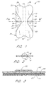
- FIG. 1 illustrates a tube retainer 10 that is configured in accordance with an embodiment of the present invention.
- the tube retainer 10 has particular utility in the context of retaining naso-gastric tubes in relation to a patient's face.
- the tube retainer 10 is accordingly illustrated and described in connection with a naso-gastric tube. It should be understood, however, that the skilled artisan can readily adapt the tube retainer for use in other applications to retain many different types of medical tubes to a patient.
- the tube retainer may have utility in securing many other types of catheters to other locations on a patient's skin.
- a removable liner 14 is visible.
- the liner 14 may be coextensive with the shape of the retainer 10 to ease manufacture.
- the removable liner 14 extends below an area covered by the remainder of the retainer 10. The liner 14 is removed before attachment of the retainer 10 to a patient or a tube.
- the liner 14 is desirably provided in two discontinuous liner pieces, an upper liner piece 16 and a lower liner piece 18, with a separation cut 19 extending below the remainder of the retainer.
- the liner 14 includes left and right notches 20, 22 at the lateral edges of the retainer 10, partially extending across the retainer 10 and partially separating the upper liner piece 16 from the lower liner piece 18. These notches 20, 22 further facilitate alignment of the retainer 10 on the patient, as well as facilitate removal of the liner 14 prior to use of the retainer 10.
- the retainer 10 narrows at a neck portion 30 of the retainer 10, relative to an upper portion 32 and a lower portion 34 of the retainer 10.
- the upper portion 32 is the mirror image of the lower portion 34 about a lateral axis (coinciding with the cut line 19 which separates the upper liner piece 16 from the lower liner piece 18).
- the lateral axis thus crosses the retainer 10 at the neck portion 30.
- the upper portion 32 comprises an upper left lobe 36 and an upper right lobe 38, which extend both laterally and longitudinally from the center of the retainer 10, thereby defining an upper edge 40 which appears concave from the view of Figure 1.
- the lower portion 34 comprises a lower left lobe 42 and a lower right lobe 44, which extend both laterally and longitudinally from the center of the retainer, thereby defining a concave lower edge 46.
- Concave left and right edges 48, 49 also result, leading to a minimal width at the lateral axis.
- the "neck” or bridge portion 30 of the retainer 10 is defined as that portion of the retainer 10 which structurally connects the upper portion 32 to the lower portion 34, where the upper portion 32 is designed to attach to the patient's skin and the lower portion is designed to attach to a medical tube.
- the neck may be defined as the narrowest portion of the retainer 10, where width is measured in a direction perpendicular to the longitudinal axis (i.e., laterally as seen from the view of Figure 1).
- the neck portion 30 comprises the area centered around the line of minimal width, of a longitudinal length at least about 5% of the total length of the retainer 10, and bounded by the side edges 48, 49.
- the longitudinal length of the neck portion 30 is at least about 10% of the total retainer length, and more desirably greater than about 20% of the total retainer length.
- at least a part of the neck portion 30 is generally between patient's nose and the medical tube and not attached to either, as will be understood by reference to Figures 4 to 6.
- a spine 50 that extends longitudinally.
- the spine 50 provides structural strength in the longitudinal direction to assist in supporting the attached tube when in use on a patient.
- the spine 50 forms a structural link between the upper portion 32 and the lower portion 34, and accordingly extends at least across the neck portion 30 of the retainer 10.
- the spine 50 extends to the lower edge 46.
- the spine 50 extends the entire length of retainer 10 along the longitudinal, axis. Such an arrangement ensures a large surface area over which the spine 50 may be secured to each of the upper portion 32 and the lower portion 34 of the retainer.
- Means of attaching the spine 50 to the upper and lower portions 32 are described below, along with a discussion of the laminate structure of the illustrated embodiment.
- the dimensions of the naso-gastric tube retainer 10 are suitably selected for a desired application, e.g., for attachment to a patient's nose and to a medical tube.
- the longitudinal length of the retainer desirably is between about 2 inches (5.08 cm) and 5 inches (12.7 cm), particularly about 3 inches (7.62 cm).
- the length of the upper portion, which must provide adhesion with the patient's skin is at least about 0.5 inch (1.27 cm), desirably greater than about 1.0 inch (2.54 cm), and particularly about 1.5 inches (3.81 cm).
- the lower portion 34 has a similar length, However, it will be understood that a smaller surface area is required for the lower portion 34 to exhibit strong enough adhesion to a medical tube.
- the lateral width for the upper portion 32 is also chosen to provide suitable adhesion with a patient's skin and therefore depends upon the length of the upper portion 32 and the adhesive used. Desirably, the width is between about 1 inch (2.54 cm) and 3 inches (7.62 cm), more desirably between about 1.3 inches (3.30 cm) and 1.7 inches (4.32 cm), and particularly about 1.5 inches (3.81 cm).
- this the lower portion 34 has a similar width. It will be understood, however, that the surface area of the lower portion need not be as great as that of the upper portion 32 in order to provide sufficient adhesion to a medical tube.
- the neck portion 30 should be narrower than the width at the lobes 36, 38 or 42, 44, while wide enough to resist tearing due to the load of the tube. While this dimension may vary greatly depending upon the materials used, the width at the neck portion 30 of the illustrated embodiment may be between about 0.05 inch (0.127 cm) and 3 inches (7.62 cm), desirably between about 0.10 inch (0.254 cm) and 2 inches (5.08 cm), and particularly about 0.5 inch (1.27 cm). In light of the additional support provided by the spine 50, however, this dimension is not critical for providing strength.
- the width of the spine 50 may vary greatly depending upon the materials used and the degree of support provided by the remaining layers.
- the spine should more narrow than the neck portion 30, so as not to interfere with the bending of the retainer to wrap around the patient's nose or the medical tube.
- the spine 50 should be more narrow than the diameter of the tube to which the retainer 10 is to attach.
- Typical naso-gastric tubes for example, may have diameters of about 0.3 inch, give or take about 0.1 inch (0.254 cm).
- the width of the spine 50 should be between about 0.05 inch (0.127 cm) and 1 inch (2.54 cm), desirably between about 0.1 inch (0.254 cm) and 0.5 inch (1.27 cm), and particularly less than about 0.3 inches (0.762 cm).
- the spine 50 has a width of about 0.25 inch (0.635 cm).
- the illustrated retainer 10 has a laminate structure.
- a first or bottom structural layer 80 is provided, which is desirably coextensive with the outline of the retainer 10 shown in the plan view of Figure 1.
- This bottom layer 60 provides a large surface area for attachment to the patient's nose or to a medical tube.
- the bottom layer 60 comprises a lightweight and flexible structural material.
- the material can be capable of breathing to allow moisture to escape outwardly, such as breathable foam or tape fabric.
- An example of a suitable material is a spunlaced polyester nonwoven fabric, available from Avery Dennison in a nominal thickness of about 0.025 inch (0.0635 cm) under the trade name MED 5707.
- An adhesive layer 61 underlies the structural layer 60, interposed between the structural layer 60 and the removable liner 14.
- the adhesive 61 desirably comprises a medical grade adhesive.
- Such adhesives exhibit an affinity for a patient's skin and for the polymeric material of most medical tubes, without irritating the patient's skin.
- An example of a suitable material is a nonsensitizing porous acrylic copolymer, which is provided on one side of the MED 5707 tape from Avery Dennison, used for the illustrated bottom structural layer 60.
- the surface of the liner 14 in contact with the adhesive 61 does not have a high affinity for the adhesive 61, and may be easily peeled away to expose the adhesive layer 61 when the retainer 10 is ready for use.
- the MED 5707 tape is provided with a densified kraft paper liner with a silicon release coating on one side for reversible adhesion to the adhesive 61.
- the illustrated retainer 10 further comprises a second or top layer 62 over the first layer 60.
- the top layer 62 is coextensive with the bottom layer 60, though it need not be.
- the top layer 62 comprises a lightweight and flexible structural material.
- the top layer 62 may also be capable of breathing to allow moisture to escape outwardly, such as foam or tape fabric.
- the top layer 12 is desirably skin-colored for aesthetic reasons, namely to blend in with the patient's skin.
- An example of a suitable material comprises the same polyester material as the illustrated bottom layer 60.
- a tan embossed version of the nonwoven polyester fabric is available from Avery Dennison in a nominal thickness of 0.011 inch (0.02794 cm) under the trade name MED 5717P.
- the spine 50 is attached to the bottom layer 60 above and below the neck portion 30 ( Figure 1) by means of a laminating adhesive.
- the spine 50 is sandwiched between the top and bottom layers 62, 60, and the layers are desirably attached along the entire length of the spine 50.
- An adhesive on the bottom surface of the top layer 62 binds the top layer 62 to the bottom layer 60, with the spine 50 secured therebetween.
- the top layer 62 of the illustrated retainer protects the integrity of the underlying layers, holds the spine in place over the bottom layer, allows outward escape of moisture, and visually blends in with the skin of the patient for aesthetic purposes.
- the spine 50 of the illustrated embodiment is internally located, it will be understood that in other embodiments the spine may be located outside one or more structural layers.
- the spine may be affixed to the top or the bottom of a structural layer.
- the spine may also be attached to the structural layer(s) by any other suitable means (e.g., the spine may be sewn to a structural layer).
- the spine 50 comprises a material of greater tensile strength than the structural layer 60 or layers 60, 62, to increase resistance to failure due to the longitudinal load exerted by a medical tube.
- the layers 60, 62 of the illustrated embodiment comprise polyester fabric with tensile strengths in the range of about 10-12lbs./inch (1752-2102 N/m)
- the tensile strength of the spine material used in conjunction with the top layer 62 and bottom layer 60 should be greater than about 12 lbs./inch (2102 N/m).
- the tensile strength of the spine material in the longitudinal direction is greater than about 15 lbs./inch (2628 N/m), more desirably greater than about 25 lbs./inch (4380 N/m), and particularly greater than about 40 lbs./inch (7008 N/m).
- the spine material is flexible with a relatively low modulus of rigidity, such that deflections of the spine 50 during normal use on a patient do not cause substantial internal stress within the retainer 10.
- Substantial internal stress is that amount of elastic force, created in reaction to deflection of the spine, which causes the retainer to lift from at least a portion of either the patient's skin or the medical tube. It has been determined that materials having a modulus of elasticity of less than about 500,000 p.s.i. (3447 MPa) do not cause substantial internal stress. For purposes of the present description, such materials are considered substantially inelastic.
- the spine material of the illustrated embodiment desirably has a modulus of elasticity of less than about 200,000 p.s.i. (1379 MPa), more desirably less than about 150,000 p.s.i. (1034 MPa), and particularly less than about 100,000 p.s.i. (689.5 MPa).
- the spine 50 is particularly advantageous for the spine 50 to be substantially inelastic and flexible in directions orthogonal to the longitudinal axis. Specifically, the spine 50 should flexibly bend along the longitudinal axis. For the illustrated embodiment, such flexibility allows the spine 50 to bend around the end of the patient's nose.
- the spine 50 is also desirably flexible in response to twisting or torsion about the longitudinal axis, to accommodate twisting motions of the tube relative to the patient's body.
- the spine 50 also desirably bends flexibly along the lateral axis. Such flexibility is particularly desirable where spine is wider than the medical tube so that the wider spine may wrap around the tube.
- the spine 50 also exhibits a shear strength sufficient to withstand tearing in the context of its intended use.
- the shear strength of the spine 50 measured in a propagating or Elmendorf tear, is at least about 0.5 lb./inch (87.6 N/m), more desirably greater than about 0.8 lb./inch (140.2 N/m), and particularly greater than about 1.2 lbs./inch (210.2 N/m).
- the spine 50 of the illustrated embodiment comprises a spun bonded olefin, paper-like material available from E.I. DuPont de Nemours, Inc. under the trade name 1073-8 TyvekTM.
- the illustrated spine 50 has a thickness between 0.001 inch (0.00254 cm) and 0,020 inch (0,0508 cm), desirably between about 0.004 inch (0.0102 cm) and 0.012 inch (0.0305 cm), and particularly between about 0.006 inch (0.0152 cm) and 0.010 inch (0.0254 cm) in order to exhibit the desired strength and elasticity set forth above.
- "Merge 18024" is a specific type of TyvekTM which is particularly advantageous for use in the medical field, available in a nominal thickness of 0.0073 inch (0.0185 cm).
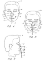
- the head of a patient 70 is depicted with a naso-gastric tube 72 inserted into the patient's right nostril 74.
- the naso-gastric retainer 10 in accordance with the illustrated embodiment is positioned in front of the patient 70 prior to adhering the retainer to the patient's nose 76 but after peeling away the removable liner 14 (Fig. 1).
- the notches 22 or separation cut 19 may be aligned with the tip of the patient's nose 76, such that the upper portion 32 of the retainer 10 is aligned with the patient's nose 76.
- the lower portion 34 is thereby aligned with the medical tube 72.
- the upper liner piece 16 (Fig. 1) may be removed first and the upper portion 32 of the retainer 10 attached to the patient's nose 76.
- the lower liner piece 18 (Fig. 1) may then be removed and the lower portion 34 of the retainer 10 attached to the medical tube 72.
- Figures 5 and 6 show the naso-gastric tube 72 attached to the patient 70 by way of the naso-gastric tube retainer 10 of the illustrated embodiment.
- the upper portion 32 of the retainer 10 serves as a nose pad, with the upper lobes 36, 38 wrapped around either side of and adhering to the patient's nose 76 while the concave upper edge 40 conforms to the bridge of the nose 76.
- the lower portion 34 of the retainer 10 serves as a tube attachment section, with the lower lobes 42, 44 wrapped around and adhering to the medical tube 72.
- the upper and lower portions 32, 34 of the retainer 10 are thus sized for adequate adhesion to a patient's skin and a medical tube, respectively.
- a narrow neck 30 between the upper portion 32 and the lower portion 34 allows flexibility to allow wrapping of the lower portion 34 around a medical tube without causing the retainer 10 to bunch. After application of the retainer 10, the neck 30 allows movement of the attached tube relative to the patient. Unfortunately, the narrow neck portion 30 is particularly susceptible to tearing.
- the spine 50 extends across the narrow neck portion 30 of the retainer, providing increased structural support for the tube attachment.
- the retainer 10 is thus less susceptible to tearing along the neck 30 and the patient 70 is subjected to fewer changes of the retainer 10 for the duration of the treatment.
- the spine 50 is flexible and substantially inelastic, allowing deflection in a horizontal plane without exerting stress on the points of adhesion. Lateral movement of the tube 72 is thereby allowed, while maintaining the tube 72 longitudinally relative to the patient 70.
Landscapes
- Health & Medical Sciences (AREA)
- Life Sciences & Earth Sciences (AREA)
- Hematology (AREA)
- Public Health (AREA)
- Engineering & Computer Science (AREA)
- Anesthesiology (AREA)
- Biomedical Technology (AREA)
- Heart & Thoracic Surgery (AREA)
- Biophysics (AREA)
- Animal Behavior & Ethology (AREA)
- General Health & Medical Sciences (AREA)
- Pulmonology (AREA)
- Veterinary Medicine (AREA)
- Media Introduction/Drainage Providing Device (AREA)
- Materials For Medical Uses (AREA)
- Orthopedics, Nursing, And Contraception (AREA)
- Investigating Or Analyzing Materials By The Use Of Ultrasonic Waves (AREA)
- Medicines Containing Material From Animals Or Micro-Organisms (AREA)
- Separation Using Semi-Permeable Membranes (AREA)
Abstract
Description
Claims (18)
- A naso-gastric tube retainer (10) having a nose end and a tube end defining a longitudinal axis therebetween, the retainer comprising:characterised in that said retainer further comprises a flexible, substantially inelastic spine (50) extending at least the length of the neck and being affixed to at least two locations on the neck that are spaced from each other along the longitudinal axis.a nose pad (32) at the nose end of the retainer, including a structural layer (60) and an adjacent adhesive layer (61);a tube attachment section (34) at the tube end of the retainer, including a structural layer (60) and an adjacent adhesive layer (61);a longitudinal neck (30) connecting the nose pad (32) to the tube attachment section (34), wherein the neck (30) is narrower in a dimension perpendicular to the longitudinal axis than each of the nose pad (32) and the tube attachment section (34);
- The naso-gastric tube retainer of claim 1, wherein the spine (50) exhibits a longitudinal tensile strength of at least about 25 lbs./inch (4380 N/m).
- The naso-gastric tube retainer of claim 1 or 2, wherein the spine (50) exhibits a longitudinal tensile strength of at least about 40 lbs./inch (7008 N/m).
- The naso-gastric tube retainer of any preceding claim, wherein the spine (50) has a modulus of elasticity of less than about 150,000 p.s.i. (1034 MPa).
- The naso-gastric tube retainer of any preceding claim, wherein the spine (50) has a modulus of elasticity of less than about 100,000 psi (689.5 MPa).
- The naso-gastric tube retainer of any preceding claim, wherein the spine (50) exhibits a shear strength in a direction perpendicular to the neck of at least about 0.8 lbs./inch (140.2 N/m).
- The naso-gastric tube retainer of any preceding claim, wherein the spine (50) exhibits a shear strength in a direction perpendicular to the neck of at least about 1.2 lbs./inch (210.2 N/m).
- The naso-gastric tube retainer of any preceding claim, wherein the structural and adhesive layers (60 and 61) of the nose pad (32) are continuous across the neck (30) with the structural and adhesive layers (60 and 61) of the tube attachment section (34), forming an integral structural layer and an integral adhesive layer.
- The naso-gastric tube retainer of any preceding claim, wherein the retainer further comprising a removable liner (14) adjacent to and directly contacting each adhesive layer (61).
- The naso-gastric tube retainer of any preceding claim, wherein the retainer further comprising a second structural layer adjacent each structural layer, each structural layer interposed between the second structural layer and the adhesive layer.
- The naso-gastric tube retainer of claim 10, wherein the spine (50) is interposed between the second structural layer and the structural layer of each of the nose pad (32) and the tube attachment section (34).
- The naso-gastric tube retainer of any preceding claim, wherein the spine (50) is coextensive with the length of the retainer (10) along the longitudinal axis.
- The naso-gastric tube retainer of any preceding claim, wherein the spine (50) is narrower than the neck.
- The naso-gastric tube retainer of any preceding claim, wherein the structural layers comprise polyester.
- The naso-gastric tube retainer of claim 14, wherein the structural layers comprise a spunlaced nonwoven fabric.
- The naso-gastric tube retainer of any preceding claim, wherein the spine (50) comprises a high-density polyethylene.
- The naso-gastric tube retainer of any preceding claim, wherein the spine (50) is secured between the nose pad (32) and the tube attachment section (34), the spine (50) being at least as narrow as the longitudinal neck of the retainer, the spine (50) at least in part formed of a material with a tensile strength greater than that of the nose pad (32) and that of the tube attachment section (34).
- The naso-gastric retainer of any preceding claim, wherein each of the nose pad (32) and tube attachment sections (34) comprises a right lobe (36 and 42) and a left lobe (38 and 44) defining a concave longitudinal end of the retainer.
Applications Claiming Priority (3)
| Application Number | Priority Date | Filing Date | Title |
|---|---|---|---|
| US789084 | 1997-01-27 | ||
| US08/789,084 US5833663A (en) | 1997-01-27 | 1997-01-27 | Naso-gastric tube retainer |
| PCT/US1998/001543 WO1998032481A1 (en) | 1997-01-27 | 1998-01-26 | Naso-gastric tube retainer |
Publications (2)
| Publication Number | Publication Date |
|---|---|
| EP0961630A1 EP0961630A1 (en) | 1999-12-08 |
| EP0961630B1 true EP0961630B1 (en) | 2005-05-18 |
Family
ID=25146544
Family Applications (1)
| Application Number | Title | Priority Date | Filing Date |
|---|---|---|---|
| EP98903758A Expired - Lifetime EP0961630B1 (en) | 1997-01-27 | 1998-01-26 | Naso-gastric tube retainer |
Country Status (9)
| Country | Link |
|---|---|
| US (1) | US5833663A (en) |
| EP (1) | EP0961630B1 (en) |
| JP (1) | JP4069462B2 (en) |
| AT (1) | ATE295751T1 (en) |
| AU (1) | AU737535B2 (en) |
| CA (1) | CA2279269C (en) |
| DE (1) | DE69830234T2 (en) |
| ES (1) | ES2239797T3 (en) |
| WO (1) | WO1998032481A1 (en) |
Cited By (1)
| Publication number | Priority date | Publication date | Assignee | Title |
|---|---|---|---|---|
| USD827144S1 (en) | 2017-09-14 | 2018-08-28 | 3M Innovative Properties Company | Nasogastric tube securement device |
Families Citing this family (29)
| Publication number | Priority date | Publication date | Assignee | Title |
|---|---|---|---|---|
| WO2000074761A1 (en) | 1999-06-08 | 2000-12-14 | Venetec International, Inc. | Medical line securement device for use with neonates |
| US6551285B1 (en) | 2000-06-08 | 2003-04-22 | Venetec International, Inc. | Medical line securement device for use with neonates |
| US6837238B2 (en) * | 2001-10-12 | 2005-01-04 | Southmedic Incorporated | Lightweight oxygen delivery device for patients |
| US8096300B2 (en) | 2004-12-03 | 2012-01-17 | Dale Medical Products, Inc. | Endotracheal tube holder |
| AT9375U1 (en) * | 2005-04-12 | 2007-09-15 | Lang Leonh | FIXING DEVICE FOR FIXING A MEDICAL TOOL INTO A BODY OPENING |
| US20060289011A1 (en) * | 2005-06-27 | 2006-12-28 | Helsel Paula A | Resilient nasal intubation tube supporter |
| WO2007028007A2 (en) | 2005-08-31 | 2007-03-08 | Venetec International, Inc. | Anchoring system for a catheter |
| US8052648B2 (en) | 2005-12-21 | 2011-11-08 | Venetec International, Inc. | Intravenous catheter anchoring device |
| US7879013B2 (en) | 2005-12-21 | 2011-02-01 | Venetec International, Inc. | Intravenous catheter anchoring device |
| US8474461B2 (en) * | 2006-06-17 | 2013-07-02 | Stephen J. Masella | Apparatus for holding nasal tubes |
| US7806873B2 (en) | 2006-07-13 | 2010-10-05 | Venetec International, Inc. | Intravenous securement device with adhesively interconnected anchoring component and permeable adhesive strip |
| US8241253B2 (en) | 2007-07-20 | 2012-08-14 | C.R. Bard, Inc. | Securement system for a medical article |
| US8394067B2 (en) | 2009-05-21 | 2013-03-12 | C.R. Bard, Inc. | Medical device securement system |
| US8598403B2 (en) * | 2010-08-10 | 2013-12-03 | Lq Product & Devices, Llc | Infant nasal septum protective device |
| GB2484719B (en) | 2010-10-21 | 2013-02-27 | Andrew Levy | Tube anchor assembly |
| US8556859B2 (en) | 2011-12-21 | 2013-10-15 | Securcath LLC | Securement device for medical fixtures |
| US20160101264A1 (en) * | 2014-10-13 | 2016-04-14 | Benjamin Bertram | Cutaneous catheter anchoring device and method of stabilizing a catheter site |
| WO2016159783A1 (en) * | 2015-03-30 | 2016-10-06 | Fisher & Paykel Healthcare Limited | Patient interface |
| WO2017034913A1 (en) * | 2015-08-21 | 2017-03-02 | 3M Innovative Properties Company | Nasogastric tube securement systems and methods of using same |
| US20200078561A1 (en) * | 2015-08-21 | 2020-03-12 | 3M Innovative Properties Company | Nasogastric Tube Securement Systems and Methods of Using Same |
| EP3337545B1 (en) | 2015-08-21 | 2021-01-13 | 3M Innovative Properties Company | Nasogastric tube securement systems |
| EP3337546B1 (en) * | 2015-08-21 | 2020-09-23 | 3M Innovative Properties Company | Nasogastric tube securement systems |
| CN107949416A (en) | 2015-08-21 | 2018-04-20 | 3M创新有限公司 | Nose catheter fixed system and its application method |
| CN113876488B (en) | 2016-05-13 | 2022-09-13 | C·R·巴德股份有限公司 | Catheter securement device including guide nose |
| CN113507957A (en) * | 2019-03-13 | 2021-10-15 | 3M创新有限公司 | Pipe fixing device |
| WO2020214856A1 (en) | 2019-04-17 | 2020-10-22 | Bard Access Systems, Inc. | Catheter securement device including extended anchor pad and release liner clasping features |
| USD928312S1 (en) | 2019-10-30 | 2021-08-17 | 3M Innovative Properties Company | Tube securement device |
| EP4247471A1 (en) * | 2020-11-20 | 2023-09-27 | Phagenesis Limited | Devices, systems, and methods for securing treatment members |
| US11944589B1 (en) | 2021-09-23 | 2024-04-02 | Carmen V. Garcia | Nasogastric tube securing device |
Family Cites Families (27)
| Publication number | Priority date | Publication date | Assignee | Title |
|---|---|---|---|---|
| US2748766A (en) * | 1953-12-23 | 1956-06-05 | Medical Fabrics Co Inc | Bandage for joint areas |
| US3046989A (en) * | 1960-09-29 | 1962-07-31 | Edward J Hill | Means for holding nasal tubes in position |
| GB934342A (en) * | 1962-07-09 | 1963-08-14 | Edward Joseph Hill | Means for holding nasal tubes in position |
| US3529597A (en) * | 1968-04-19 | 1970-09-22 | George T Fuzak | Fingertip bandage |
| US3556096A (en) * | 1968-09-27 | 1971-01-19 | Scholl Mfg Co Inc | Cushioning and protective surgical bandage |
| US3677250A (en) * | 1971-02-11 | 1972-07-18 | Morton I Thomas | Tabbed anchoring tape means |
| US4057066A (en) * | 1976-09-02 | 1977-11-08 | Taylor Harry E | Catheter holder for securing a urethral catheter to a patient |
| US4120304A (en) * | 1976-10-12 | 1978-10-17 | Moor Burdette J | Naso-gastric tube holder |
| US4142527A (en) * | 1977-02-07 | 1979-03-06 | Garcia Nelson C | Endotracheal tube holder |
| US4133307A (en) * | 1977-05-09 | 1979-01-09 | Ness Richard A | Traction device |
| US4480639A (en) * | 1982-01-18 | 1984-11-06 | Peterson Edward D | Medical tube retaining device |
| US4660555A (en) * | 1984-09-21 | 1987-04-28 | Payton Hugh W | Oxygen delivery and administration system |
| US5037397A (en) * | 1985-05-03 | 1991-08-06 | Medical Distributors, Inc. | Universal clamp |
| US4838867A (en) * | 1985-05-03 | 1989-06-13 | Glenda G. Kalt | Universal clamp |
| US4742824A (en) * | 1986-11-19 | 1988-05-10 | Hugh W. Payton | Oxygen tube support patch |
| US4823789A (en) * | 1988-02-16 | 1989-04-25 | Genetic Laboratories, Inc. | Nose tube anchoring strip |
| US4932943A (en) * | 1988-05-23 | 1990-06-12 | Hollister Incorporated | Nasogastric tube holding device |
| US5261893A (en) * | 1989-04-03 | 1993-11-16 | Zamierowski David S | Fastening system and method |
| US4986815A (en) * | 1989-12-11 | 1991-01-22 | Hollister Incorporated | Nasogastric tube holding device |
| US4976700A (en) * | 1990-02-07 | 1990-12-11 | Tollini Dennis R | Medical securing tape |
| US5156641A (en) * | 1990-03-07 | 1992-10-20 | Mayo Foundation For Medical Education And Research | Naso-gastric catheter anchor system |
| US5533499A (en) * | 1991-06-10 | 1996-07-09 | Creative Integration & Design, Inc. | Nasal dilator |
| US5135506A (en) * | 1991-06-10 | 1992-08-04 | Conmed Corporation | Cannula holding device |
| US5295950A (en) * | 1992-10-21 | 1994-03-22 | Godley Frederick A | Ear pressure dressing |
| US5292312A (en) * | 1993-01-08 | 1994-03-08 | Struckmeyer Corporation | Universal tube lumen catheter holder |
| US5468231A (en) * | 1994-03-10 | 1995-11-21 | Minnesota Mining And Manufacturing Company | Refastenable tube and cable restraint for surgical use |
| US5520656A (en) * | 1995-03-29 | 1996-05-28 | Byrd; Timothy N. | Medical tube/wire holding device and associated tube/wire holding method |
-
1997
- 1997-01-27 US US08/789,084 patent/US5833663A/en not_active Expired - Lifetime
-
1998
- 1998-01-26 WO PCT/US1998/001543 patent/WO1998032481A1/en active IP Right Grant
- 1998-01-26 EP EP98903758A patent/EP0961630B1/en not_active Expired - Lifetime
- 1998-01-26 AU AU60444/98A patent/AU737535B2/en not_active Ceased
- 1998-01-26 AT AT98903758T patent/ATE295751T1/en not_active IP Right Cessation
- 1998-01-26 DE DE69830234T patent/DE69830234T2/en not_active Expired - Fee Related
- 1998-01-26 CA CA002279269A patent/CA2279269C/en not_active Expired - Fee Related
- 1998-01-26 JP JP53223198A patent/JP4069462B2/en not_active Expired - Fee Related
- 1998-01-26 ES ES98903758T patent/ES2239797T3/en not_active Expired - Lifetime
Cited By (1)
| Publication number | Priority date | Publication date | Assignee | Title |
|---|---|---|---|---|
| USD827144S1 (en) | 2017-09-14 | 2018-08-28 | 3M Innovative Properties Company | Nasogastric tube securement device |
Also Published As
| Publication number | Publication date |
|---|---|
| CA2279269C (en) | 2008-10-07 |
| WO1998032481A1 (en) | 1998-07-30 |
| JP4069462B2 (en) | 2008-04-02 |
| AU6044498A (en) | 1998-08-18 |
| ATE295751T1 (en) | 2005-06-15 |
| ES2239797T3 (en) | 2005-10-01 |
| EP0961630A1 (en) | 1999-12-08 |
| AU737535B2 (en) | 2001-08-23 |
| US5833663A (en) | 1998-11-10 |
| CA2279269A1 (en) | 1998-07-30 |
| DE69830234D1 (en) | 2005-06-23 |
| JP2001521412A (en) | 2001-11-06 |
| DE69830234T2 (en) | 2006-01-26 |
Similar Documents
| Publication | Publication Date | Title |
|---|---|---|
| EP0961630B1 (en) | Naso-gastric tube retainer | |
| US4823789A (en) | Nose tube anchoring strip | |
| US4838878A (en) | Universal clamp | |
| US8616198B2 (en) | Nasal dilator | |
| US5664581A (en) | Intravenous tubing secure strap | |
| JP4169243B2 (en) | Surgical drape and suction head for wound healing | |
| US5156641A (en) | Naso-gastric catheter anchor system | |
| US4738662A (en) | Universal clamp | |
| US5037397A (en) | Universal clamp | |
| US5513635A (en) | Nasal cannula anchoring apparatus | |
| JPH06502772A (en) | General purpose clamp | |
| US5308339A (en) | Universal clamp | |
| JPS63501477A (en) | General purpose clamp | |
| US11452848B2 (en) | Catheter securement device including extended anchor pad and release liner clasping features | |
| US6165156A (en) | Device and method for fastening a catheter | |
| JP2008509712A (en) | Compression belt | |
| CA1279054C (en) | Universal clamp | |
| US20110166529A1 (en) | Medical appliance securing device | |
| US10596350B2 (en) | Catheter securement device with dual retention straps | |
| JPH03501818A (en) | General purpose medical supplies | |
| US9233228B1 (en) | Medical appliance securing device | |
| CN113507957A (en) | Pipe fixing device | |
| US20070071799A1 (en) | Anchor point for affixing tubes and the like to skin | |
| CN110236955A (en) | Nasal gastrointestinal tube fixes device | |
| WO2000074761A1 (en) | Medical line securement device for use with neonates |
Legal Events
| Date | Code | Title | Description |
|---|---|---|---|
| PUAI | Public reference made under article 153(3) epc to a published international application that has entered the european phase |
Free format text: ORIGINAL CODE: 0009012 |
|
| 17P | Request for examination filed |
Effective date: 19990803 |
|
| AK | Designated contracting states |
Kind code of ref document: A1 Designated state(s): AT BE CH DE DK ES FI FR GB GR IE IT LI LU MC NL PT SE |
|
| 17Q | First examination report despatched |
Effective date: 20030707 |
|
| RAP1 | Party data changed (applicant data changed or rights of an application transferred) |
Owner name: VENETEC INTERNATIONAL, INC. |
|
| GRAP | Despatch of communication of intention to grant a patent |
Free format text: ORIGINAL CODE: EPIDOSNIGR1 |
|
| GRAS | Grant fee paid |
Free format text: ORIGINAL CODE: EPIDOSNIGR3 |
|
| GRAA | (expected) grant |
Free format text: ORIGINAL CODE: 0009210 |
|
| AK | Designated contracting states |
Kind code of ref document: B1 Designated state(s): AT BE CH DE DK ES FI FR GB GR IE IT LI LU MC NL PT SE |
|
| PG25 | Lapsed in a contracting state [announced via postgrant information from national office to epo] |
Ref country code: NL Free format text: LAPSE BECAUSE OF FAILURE TO SUBMIT A TRANSLATION OF THE DESCRIPTION OR TO PAY THE FEE WITHIN THE PRESCRIBED TIME-LIMIT Effective date: 20050518 Ref country code: LI Free format text: LAPSE BECAUSE OF FAILURE TO SUBMIT A TRANSLATION OF THE DESCRIPTION OR TO PAY THE FEE WITHIN THE PRESCRIBED TIME-LIMIT Effective date: 20050518 Ref country code: FI Free format text: LAPSE BECAUSE OF FAILURE TO SUBMIT A TRANSLATION OF THE DESCRIPTION OR TO PAY THE FEE WITHIN THE PRESCRIBED TIME-LIMIT Effective date: 20050518 Ref country code: CH Free format text: LAPSE BECAUSE OF FAILURE TO SUBMIT A TRANSLATION OF THE DESCRIPTION OR TO PAY THE FEE WITHIN THE PRESCRIBED TIME-LIMIT Effective date: 20050518 Ref country code: BE Free format text: LAPSE BECAUSE OF FAILURE TO SUBMIT A TRANSLATION OF THE DESCRIPTION OR TO PAY THE FEE WITHIN THE PRESCRIBED TIME-LIMIT Effective date: 20050518 Ref country code: AT Free format text: LAPSE BECAUSE OF FAILURE TO SUBMIT A TRANSLATION OF THE DESCRIPTION OR TO PAY THE FEE WITHIN THE PRESCRIBED TIME-LIMIT Effective date: 20050518 |
|
| REG | Reference to a national code |
Ref country code: GB Ref legal event code: FG4D |
|
| REG | Reference to a national code |
Ref country code: CH Ref legal event code: EP |
|
| REG | Reference to a national code |
Ref country code: IE Ref legal event code: FG4D |
|
| REF | Corresponds to: |
Ref document number: 69830234 Country of ref document: DE Date of ref document: 20050623 Kind code of ref document: P |
|
| PG25 | Lapsed in a contracting state [announced via postgrant information from national office to epo] |
Ref country code: SE Free format text: LAPSE BECAUSE OF FAILURE TO SUBMIT A TRANSLATION OF THE DESCRIPTION OR TO PAY THE FEE WITHIN THE PRESCRIBED TIME-LIMIT Effective date: 20050818 Ref country code: DK Free format text: LAPSE BECAUSE OF FAILURE TO SUBMIT A TRANSLATION OF THE DESCRIPTION OR TO PAY THE FEE WITHIN THE PRESCRIBED TIME-LIMIT Effective date: 20050818 |
|
| REG | Reference to a national code |
Ref country code: GR Ref legal event code: EP Ref document number: 20050402277 Country of ref document: GR |
|
| REG | Reference to a national code |
Ref country code: ES Ref legal event code: FG2A Ref document number: 2239797 Country of ref document: ES Kind code of ref document: T3 |
|
| PG25 | Lapsed in a contracting state [announced via postgrant information from national office to epo] |
Ref country code: PT Free format text: LAPSE BECAUSE OF FAILURE TO SUBMIT A TRANSLATION OF THE DESCRIPTION OR TO PAY THE FEE WITHIN THE PRESCRIBED TIME-LIMIT Effective date: 20051024 |
|
| REG | Reference to a national code |
Ref country code: CH Ref legal event code: PL |
|
| NLV1 | Nl: lapsed or annulled due to failure to fulfill the requirements of art. 29p and 29m of the patents act | ||
| PG25 | Lapsed in a contracting state [announced via postgrant information from national office to epo] |
Ref country code: IE Free format text: LAPSE BECAUSE OF NON-PAYMENT OF DUE FEES Effective date: 20060126 |
|
| PG25 | Lapsed in a contracting state [announced via postgrant information from national office to epo] |
Ref country code: MC Free format text: LAPSE BECAUSE OF NON-PAYMENT OF DUE FEES Effective date: 20060131 Ref country code: LU Free format text: LAPSE BECAUSE OF NON-PAYMENT OF DUE FEES Effective date: 20060131 |
|
| PLBE | No opposition filed within time limit |
Free format text: ORIGINAL CODE: 0009261 |
|
| STAA | Information on the status of an ep patent application or granted ep patent |
Free format text: STATUS: NO OPPOSITION FILED WITHIN TIME LIMIT |
|
| ET | Fr: translation filed | ||
| 26N | No opposition filed |
Effective date: 20060221 |
|
| REG | Reference to a national code |
Ref country code: IE Ref legal event code: MM4A |
|
| PGFP | Annual fee paid to national office [announced via postgrant information from national office to epo] |
Ref country code: ES Payment date: 20090218 Year of fee payment: 12 |
|
| PGFP | Annual fee paid to national office [announced via postgrant information from national office to epo] |
Ref country code: DE Payment date: 20090123 Year of fee payment: 12 |
|
| PGFP | Annual fee paid to national office [announced via postgrant information from national office to epo] |
Ref country code: IT Payment date: 20090128 Year of fee payment: 12 |
|
| PGFP | Annual fee paid to national office [announced via postgrant information from national office to epo] |
Ref country code: FR Payment date: 20090113 Year of fee payment: 12 |
|
| PGFP | Annual fee paid to national office [announced via postgrant information from national office to epo] |
Ref country code: GR Payment date: 20091215 Year of fee payment: 13 |
|
| REG | Reference to a national code |
Ref country code: FR Ref legal event code: ST Effective date: 20100930 |
|
| PG25 | Lapsed in a contracting state [announced via postgrant information from national office to epo] |
Ref country code: FR Free format text: LAPSE BECAUSE OF NON-PAYMENT OF DUE FEES Effective date: 20100201 |
|
| PG25 | Lapsed in a contracting state [announced via postgrant information from national office to epo] |
Ref country code: DE Free format text: LAPSE BECAUSE OF NON-PAYMENT OF DUE FEES Effective date: 20100803 |
|
| PG25 | Lapsed in a contracting state [announced via postgrant information from national office to epo] |
Ref country code: IT Free format text: LAPSE BECAUSE OF NON-PAYMENT OF DUE FEES Effective date: 20100126 |
|
| REG | Reference to a national code |
Ref country code: ES Ref legal event code: FD2A Effective date: 20110408 |
|
| PG25 | Lapsed in a contracting state [announced via postgrant information from national office to epo] |
Ref country code: ES Free format text: LAPSE BECAUSE OF NON-PAYMENT OF DUE FEES Effective date: 20110324 |
|
| PG25 | Lapsed in a contracting state [announced via postgrant information from national office to epo] |
Ref country code: ES Free format text: LAPSE BECAUSE OF NON-PAYMENT OF DUE FEES Effective date: 20100127 |
|
| PG25 | Lapsed in a contracting state [announced via postgrant information from national office to epo] |
Ref country code: GR Free format text: LAPSE BECAUSE OF NON-PAYMENT OF DUE FEES Effective date: 20110802 |
|
| PGFP | Annual fee paid to national office [announced via postgrant information from national office to epo] |
Ref country code: GB Payment date: 20120125 Year of fee payment: 15 |
|
| GBPC | Gb: european patent ceased through non-payment of renewal fee |
Effective date: 20130126 |
|
| PG25 | Lapsed in a contracting state [announced via postgrant information from national office to epo] |
Ref country code: GB Free format text: LAPSE BECAUSE OF NON-PAYMENT OF DUE FEES Effective date: 20130126 |