EP0961575B1 - A medical device for the diagnosis of cartilage degeneration via spatial mapping of compression-induced electrical potentials - Google Patents
A medical device for the diagnosis of cartilage degeneration via spatial mapping of compression-induced electrical potentials Download PDFInfo
- Publication number
- EP0961575B1 EP0961575B1 EP98902884A EP98902884A EP0961575B1 EP 0961575 B1 EP0961575 B1 EP 0961575B1 EP 98902884 A EP98902884 A EP 98902884A EP 98902884 A EP98902884 A EP 98902884A EP 0961575 B1 EP0961575 B1 EP 0961575B1
- Authority
- EP
- European Patent Office
- Prior art keywords
- electrodes
- cartilage
- medical apparatus
- streaming
- potentials
- Prior art date
- Legal status (The legal status is an assumption and is not a legal conclusion. Google has not performed a legal analysis and makes no representation as to the accuracy of the status listed.)
- Expired - Lifetime
Links
Images


Classifications
-
- A—HUMAN NECESSITIES
- A61—MEDICAL OR VETERINARY SCIENCE; HYGIENE
- A61B—DIAGNOSIS; SURGERY; IDENTIFICATION
- A61B5/00—Measuring for diagnostic purposes; Identification of persons
- A61B5/45—For evaluating or diagnosing the musculoskeletal system or teeth
- A61B5/4514—Cartilage
-
- A—HUMAN NECESSITIES
- A61—MEDICAL OR VETERINARY SCIENCE; HYGIENE
- A61B—DIAGNOSIS; SURGERY; IDENTIFICATION
- A61B5/00—Measuring for diagnostic purposes; Identification of persons
- A61B5/103—Measuring devices for testing the shape, pattern, colour, size or movement of the body or parts thereof, for diagnostic purposes
-
- A—HUMAN NECESSITIES
- A61—MEDICAL OR VETERINARY SCIENCE; HYGIENE
- A61B—DIAGNOSIS; SURGERY; IDENTIFICATION
- A61B5/00—Measuring for diagnostic purposes; Identification of persons
- A61B5/24—Detecting, measuring or recording bioelectric or biomagnetic signals of the body or parts thereof
- A61B5/25—Bioelectric electrodes therefor
- A61B5/263—Bioelectric electrodes therefor characterised by the electrode materials
-
- A—HUMAN NECESSITIES
- A61—MEDICAL OR VETERINARY SCIENCE; HYGIENE
- A61B—DIAGNOSIS; SURGERY; IDENTIFICATION
- A61B5/00—Measuring for diagnostic purposes; Identification of persons
- A61B5/24—Detecting, measuring or recording bioelectric or biomagnetic signals of the body or parts thereof
- A61B5/25—Bioelectric electrodes therefor
- A61B5/279—Bioelectric electrodes therefor specially adapted for particular uses
-
- A—HUMAN NECESSITIES
- A61—MEDICAL OR VETERINARY SCIENCE; HYGIENE
- A61B—DIAGNOSIS; SURGERY; IDENTIFICATION
- A61B2562/00—Details of sensors; Constructional details of sensor housings or probes; Accessories for sensors
- A61B2562/02—Details of sensors specially adapted for in-vivo measurements
- A61B2562/0209—Special features of electrodes classified in A61B5/24, A61B5/25, A61B5/283, A61B5/291, A61B5/296, A61B5/053
- A61B2562/0217—Electrolyte containing
-
- A—HUMAN NECESSITIES
- A61—MEDICAL OR VETERINARY SCIENCE; HYGIENE
- A61B—DIAGNOSIS; SURGERY; IDENTIFICATION
- A61B2562/00—Details of sensors; Constructional details of sensor housings or probes; Accessories for sensors
- A61B2562/04—Arrangements of multiple sensors of the same type
- A61B2562/043—Arrangements of multiple sensors of the same type in a linear array
-
- A—HUMAN NECESSITIES
- A61—MEDICAL OR VETERINARY SCIENCE; HYGIENE
- A61B—DIAGNOSIS; SURGERY; IDENTIFICATION
- A61B5/00—Measuring for diagnostic purposes; Identification of persons
- A61B5/45—For evaluating or diagnosing the musculoskeletal system or teeth
- A61B5/4528—Joints
Definitions
- the present invention relates to a medical apparatus for early detection and diagnosis of cartilage degeneration and a method for using such apparatus.
- OA osteoarthritis
- rheumatoid arthritis Several of these degenerative joint processes are slow but progressive, requiring several years or decades to attain a symptomatic state which can only then be currently diagnosed using radiological and arthroscopic techniques. Unfortunately, the tissue damage accrued during this long period of progressive degeneration appears to be essentially irreversible, rendering the sole treatment of such conditions to be joint replacement. These costly treatments in themselves are of transitory benefit and may have to be repeated several times throughout the lifetime of the patient.
- One primary reason for the near exclusive use of radical and partial treatments such as joint replacement is the lack of diagnostic tools capable of detecting cartilage degeneration in the early and potentially reversible stages.
- osteoarthritis The most prevalent and costly joint disorder, osteoarthritis (OA), is currently diagnosed at a late stage based on physical examination (pain, swelling, deformity, joint enlargement, limitation of motion, osteophyte formation), X-ray and magnetic resonance imaging (MRI), which is a radiology imaging (joint space narrowing, reduced cartilage thickness, osteophyte formation, subchondral bone sclerosis), and by visual arthroscopy (cartilage fissuring, fibrillation, local erosion).
- physical examination pain, swelling, deformity, joint enlargement, limitation of motion, osteophyte formation
- MRI X-ray and magnetic resonance imaging
- MRI magnetic resonance imaging
- visual arthroscopy cartilage fissuring, fibrillation, local erosion
- Proposed methods for early detection and follow-up of cartilage degeneration in osteoarthritis have been based on serum and synovial fluid molecular markers, refined MRI, and evaluation of cartilage mechanical properties (International Application published under the publication number WO 93/02619 in the name of Kiviranta and Jurvelin and U.S. Patent No. 5,503,162 in the name of Athanasiou et al.) or electromechanical properties (U.S. Patent No. 5,246,013 in the name of Frank et al. y, WO 91/09568 (MASSACHUSETTS INST TECHNOLOGY)) via non-visual arthroscopic apparatus.
- Said WO application relates to an arthroscopic probe which administers an electric current to an articular surface to be tested and measures, further to the application of said electric current, a shift of the charges in the synovial liquid in order to measure the cartilage degradation.
- a precipitous loss of aggrecan is one of the earliest detectable events in osteoarthritis.
- the ability of cartilage to withstand compressive forces is tightly linked to the entrapment of highly concentrated aggrecan within the collagen network.
- Aggrecan is a highly sulfated and carboxylated molecule, leading to the presence of a high concentration of ionized negative charge groups covalently linked to the macromolecule. Compressive stiffness of cartilage is therefore in a large part due to repulsive electrostatic forces present between the charged units of aggrecan.
- the loss of aggrecan in osteoarthritis represents a significant functional tissue injury.
- Tissue compression convects interstitial fluid containing an excess of mobile positively charged counterions past the fixed negatively charged aggrecan to generate electrical fields and potentials, the latter being called streaming potentials.
- streaming potentials The amplitudes and dynamics of these electromechanical phenomena reflect the physical function of cartilage, with special reference to the contribution of aggrecan.
- One feature of the present invention is to provide a medical apparatus for early detection of cartilage degradation.
- Another feature of the present invention is to provide a medical apparatus for use in fundamental research on progressive degeneration of cartilage and treatments thereof, allowing monitoring of tissue health during extended periods of time.
- Another feature of the present invention is to provide an arthroscopic apparatus for mechanical and electromechanical evaluation of articular cartilage.
- Another feature of the present invention is to provide an electromechanical diagnostic apparatus based on a direct evaluation of physical function with particular sensitivity to the most labile and dynamic molecular component in osteoarthritis, that is aggrecan, allowing for an early diagnosis and follow-up of the disease.
- the above features preferably provide an arthroscopic apparatus for early detection of degradation in cartilage.
- the arthroscopic apparatus comprises at least two platinum point electrodes, immobilized on a solid surface for measuring the streaming potentials of cartilage, a front-end signal processor located in proximity of the electrode and comprising a voltage follower having a high input impedance and a low bias current to process signals received from the electrodes and maximize rejection of common-modes of measured differential voltages between adjacent electrodes, an abutment surface recessed from the electrodes for allowing the electrodes to be pressed in the cartilage until said cartilage abuts against the surface and means for analytical interpretation of data received from the processor for comparing the data received with other stored data obtained from given tissues affected by osteoarthritis at a given degree.
- the front-end signal processor reduces noise pick up and microphonic effects.
- the arthroscopic apparatus is sized and shaped to be introduced in an arthroscopic opening of about 2 to 6 mm of diameter and allows for spatially and temporally resolving the streaming potential between the electrodes.
- the above features also provide a method for detecting and mapping degradation in cartilage, in vitro.
- the method is defined in claim 16.
- the method may further comprise the step of comparing the measured streaming potentials with stored streaming potentials.
- the potentials measured with the apparatus in accordance with the present invention directly reflect articular cartilage function (unlike biochemical markers and imaging modalities).
- the electrical signals resulting from the measured potential are directly dependent on, and very sensitive to, the presence of one of the most labile and important molecules lost from cartilage in arthritis, that is aggrecan.
- the small size of the point electrodes allows for ease of arthroscopic use and high resolution maps of streaming potentials.
- the maps may be resolved in two dimensions.
- a medical apparatus to detect progressive degeneration of cartilage Fig. 1 illustrates a medical apparatus 1 that may be used in fundamental research to follow up in vitro degeneration of cartilage. This apparatus 1 may also be useful in assessing integrity of cartilage before, during or after treatment of that cartilage with drugs or chemical compounds, therefore allowing evaluation of the effects of drugs or chemical compounds on the cartilage.
- the apparatus 1 illustrated in Fig. 1 comprises a vessel 3 defining an enclosure having four sidewalls 5 and a rigid bottom wall 7 for containing a liquid 9 therein.
- An epoxy cylinder 11 containing four electrodes 13 is located on the bottom wall 7 at the center of the vessel 3.
- the electrodes 13 are connected to a signal conditioning module 15, which is itself connected to a computer 17 for interpreting and analyzing the data received from the module 15.
- the apparatus 1, according to this embodiment of the invention also comprises an actuator and a load cell 19 for applying a compression on a disk of cartilage 21 when the load cell 19 is positioned on the disk of cartilage, thereby producing a deformation of the cartilage 21.
- the electrodes 13 are platinum wires 12 secured through a nylon mesh producing 50 ⁇ m diameter point electrodes.
- the platinum wires 12 are cast into the epoxy cylinder 11 and exposed as a linear array with a regular center-to-center distance of 380 ⁇ m (determined by the nylon mesh), covering a total distance of 1.14 mm.
- the cylinder 11 containing the electrodes 13 is fixed to the bottom wall 7 of the vessel 3.
- the exposed surfaces of the platinum electrodes 13, at the surface of the bottom wall 7 are further platinized using electrochemical deposition to reduce the contact impedance of the electrodes 13. Electrical signals from the electrodes 13 are passed through the signal conditioning module 15 before being received by the computer 17.
- the vessel 3 is mounted in a micromechanical testing apparatus comprising the load cell 19 which is fixed to a precision actuator (not illustrated) for precisely positioning the load cell 19 over the electrodes 13 at a given distance thereof, and applying, in use, a given pressure along arrow 14 on the cartilage 21 against the electrodes 13.
- the electrodes 13, as described above, allow for a spatial resolution of the streaming potentials of the order of 0.38 mm, allowing to produce a streaming potential map.
- the electrodes 13 preferably have a diameter smaller than 500 ⁇ m and more preferably smaller than 100 ⁇ m. They may be point electrodes or circular electrodes. They could be made of other metals such as iridium or gold.
- the minimal number of electrodes used in accordance with the present invention is two. When more than two electrodes are used, they may be placed in such a manner as to define more than one axis to evaluate and resolve streaming potentials spatially in more than one dimension, such as length and width for example.
- the specialized signal conditioning module 15 is specifically designed for interfacing with the electrodes 13.
- the module 15 is mounted in proximity to the electrodes 13 to minimize noise pickup and microphonic effects.
- the signal conditioning module 15 may also be mounted further from the electrodes, provided that the electrodes are shielded to minimize noise pickup and microphonic effects.
- Fig. 9 shows a block diagram of a module used in an apparatus comprising two electrodes.
- the module comprises a voltage follower 37, a low-pass filter 39, a high-pass filter 41 and an amplifier 43.
- the voltage follower has a high input impedance ( »100 Mohm; 5 pF) and low bias current ( ⁇ 1 pAmp) to maximize rejection of common-modes of measured differential voltages between adjacent electrodes.
- the high input impedance of the voltage follower is required due to the relatively high impedance of the interface between the platinum wires and the electrolyte milieu.
- the input impedance of the first stage of the signal conditioning module must be significantly higher than this contact impedance to avoid the effect of a voltage divider.
- the precision actuator may be replaced by any means, such as an electromechanical, piezoelectric or manual means, for accurately supplying a defined compressive displacement of the electrodes surface into the cartilage.
- the computer 17 uses an analytical method of data interpretation to correlate imposed compressive displacements and measured electrical potentials to the composition and structure of the cartilage under test. This method relies on detected temporal and spatial variations of the streaming potentials across the tissue surface. A characterization of normal maps and maps typical of tissue deterioration at various degree due to osteoarthritis will indicate the degree of health or disease of an unknown tissue.
- the apparatus illustrated in Figs. 1 and 2 may be used in research to evaluate effects of chemical compounds or drugs on the cartilage.
- pieces of normal or abnormal cartilage may be cut from humans or animal models and analyzed.
- the pieces may also be submitted in culture to the chemical compounds or drugs. In doing so, it is possible to identify new chemical compounds or drugs to be used for the treatment or prophylaxis of osteoarthritis.
- FIG. 6 Another preferred embodiment is illustrated in Fig. 6.
- This second embodiment illustrates a clinical apparatus 23 to evaluate human articular cartilage function during an arthroscopy.
- the clinical apparatus 23 is embodied in a probe 25 resembling a pen.
- the probe 25 is connected to the computer 17 for data analysis.
- the probe 25 has a free end 27 provided with a tip 27' comprising point electrodes 33, an abutment surface 29 and the signal conditioning module 35 which is embedded in the tip 27', in close proximity of the electrodes 33.
- Fig. 7 illustrates an end view of the free end 27 and the tip 27' of the probe 25.
- Six electrodes 33 are immobilized in an array in the tip 27'.
- the abutment surface 29 illustrated in Fig. 8 is recessed compared to the tip 27'. Accordingly, the abutment surface 29 is used to create a defined compressive displacement on the cartilage.
- the tip 27' is applied on, and pressed against the cartilage until the abutment surface 29 rests on the cartilage. At this point, the tip 27' and the protruding electrodes 33 effect a compression on the cartilage inducing a streaming potential and allowing to measure and map this streaming potential.
- the potential measured by the electrodes 33 is sent to the signal conditioning module 35 which relays the data to the computer 17, allowing for a comparison of the map of streaming potential of the analyzed cartilage with typical maps of known healthy tissues.
- the overall diameter of the probe 25 of the clinical apparatus 23 which must be inserted into the joint can be much smaller than the arthroscopic opening (2-6 mm).
- the displacement of the electrodes is effected manually but precisely controlled by forcing the tip 27' into the cartilage until the abutment surface 29 stops the tip 27' from deforming the cartilage.
- the type of applied displacement is predetermined by the step between the face of the tip and the abutment surface.
- the resulting electrical signals vary after the compressive force is applied as they tend to an equilibrium. The amplitude of these signals have been proven to be strongly dependent on the integrity of the cartilage by using a cytokine-mediated (interleukin-1) in vitro cartilage degradation model.
- FIG. 3 An example of the raw data obtained with the apparatus of Figs. 1 and 2 is shown in Fig. 3 for a test at a frequency of 1 Hz using a 5 ⁇ m displacement amplitude.
- Figs. 3a to 3e illustrate the position, the load data and the differences of voltage present between three adjacent electrodes 13 contacting the articular disk surface 21, respectively.
- the voltage V1 is the streaming potential present between the center of the disk and 380 ⁇ m away from that center; voltage V2 is the next incremental streaming potential from 380 ⁇ m to 760 ⁇ m, and V3 is another incremental streaming potential from 760 ⁇ m to 1140 ⁇ m.
- the amplitude of the incremental streaming potential V1, V2 and V3 increases from the disk center to the periphery, demonstrating the inherent spatial variation of the electric field, induced by the actuator.
- a streaming potential radial profile can be constructed by taking the reference potential as that of the most peripheral electrode at 1.14mm from the disk center 21.
- Fig. 3 illustrates the electrical signals obtained from the apparatus and their spatial dependence.
- the magnitude and phase of V1, V2 and V3 in Figs. 3c to 3e depend on several factors including the geometry of the specimen, loading configuration, loading frequency and amplitude, content and distribution of charged species (aggrecan) in the tested issue, and degree of immobilization of aggrecan via entrapment in the collagen network.
- the ability to resolve streaming potentials on such a small spatial scale is an important aspect of the invention. Using this ability allows to discriminate between the factors listed above so that specific information on the distribution and content of aggrecan, and its immobilization in the collagen network can be obtained, providing for disease diagnosis.
- Figs. 4a and 4b The amplitude and phase of the radial profile of the potential obtained with the apparatus of Figs. 1 and 2 is shown in Figs. 4a and 4b, respectively, for three different frequencies conducted at a 5 ⁇ m amplitude.
- the reference for the potential phase is the phase of the applied axial displacement (see Fig. 3a).
- Figs. 4a, 4b and 5 illustrate the effects of frequency and amplitude on the measured signals for a healthy cartilage disk tested in the geometry of unconfined compression.
- Fig. 4a shows that the streaming potentials tend to increase in magnitude with higher frequencies.
- Fig. 4b shows that these streaming potentials tend to become more out of phase with the displacement at lower frequencies.
- Fig. 5 The amplitude of the radial streaming potential profile for three different displacement amplitudes at 1 Hz is shown in Fig. 5. These are the first spatially resolved ( ⁇ lmm resolution) measurements of streaming potential in loaded cartilage. Fig. 5 shows that the streaming potentials are approximately proportional to the applied displacement amplitude.
Landscapes
- Health & Medical Sciences (AREA)
- Life Sciences & Earth Sciences (AREA)
- General Health & Medical Sciences (AREA)
- Surgery (AREA)
- Pathology (AREA)
- Engineering & Computer Science (AREA)
- Biomedical Technology (AREA)
- Heart & Thoracic Surgery (AREA)
- Medical Informatics (AREA)
- Veterinary Medicine (AREA)
- Public Health (AREA)
- Animal Behavior & Ethology (AREA)
- Biophysics (AREA)
- Physics & Mathematics (AREA)
- Molecular Biology (AREA)
- Dentistry (AREA)
- Oral & Maxillofacial Surgery (AREA)
- Orthopedic Medicine & Surgery (AREA)
- Rheumatology (AREA)
- Investigating Or Analysing Biological Materials (AREA)
- Magnetic Resonance Imaging Apparatus (AREA)
- Electrotherapy Devices (AREA)
- Measurement And Recording Of Electrical Phenomena And Electrical Characteristics Of The Living Body (AREA)
- Apparatus For Radiation Diagnosis (AREA)
- Measuring And Recording Apparatus For Diagnosis (AREA)
Abstract
Description
- The present invention relates to a medical apparatus for early detection and diagnosis of cartilage degeneration and a method for using such apparatus.
- The physical and biochemical degeneration of articular cartilage constitutes the hallmark of several diseases of the joint including osteoarthritis (OA) and rheumatoid arthritis. Several of these degenerative joint processes are slow but progressive, requiring several years or decades to attain a symptomatic state which can only then be currently diagnosed using radiological and arthroscopic techniques. Unfortunately, the tissue damage accrued during this long period of progressive degeneration appears to be essentially irreversible, rendering the sole treatment of such conditions to be joint replacement. These costly treatments in themselves are of transitory benefit and may have to be repeated several times throughout the lifetime of the patient. One primary reason for the near exclusive use of radical and partial treatments such as joint replacement is the lack of diagnostic tools capable of detecting cartilage degeneration in the early and potentially reversible stages.
- The most prevalent and costly joint disorder, osteoarthritis (OA), is currently diagnosed at a late stage based on physical examination (pain, swelling, deformity, joint enlargement, limitation of motion, osteophyte formation), X-ray and magnetic resonance imaging (MRI), which is a radiology imaging (joint space narrowing, reduced cartilage thickness, osteophyte formation, subchondral bone sclerosis), and by visual arthroscopy (cartilage fissuring, fibrillation, local erosion). Proposed methods for early detection and follow-up of cartilage degeneration in osteoarthritis (OA) have been based on serum and synovial fluid molecular markers, refined MRI, and evaluation of cartilage mechanical properties (International Application published under the publication number WO 93/02619 in the name of Kiviranta and Jurvelin and U.S. Patent No. 5,503,162 in the name of Athanasiou et al.) or electromechanical properties (U.S. Patent No. 5,246,013 in the name of Frank et al. y, WO 91/09568 (MASSACHUSETTS INST TECHNOLOGY)) via non-visual arthroscopic apparatus. Said WO application relates to an arthroscopic probe which administers an electric current to an articular surface to be tested and measures, further to the application of said electric current, a shift of the charges in the synovial liquid in order to measure the cartilage degradation. These proposed early detection methods are still in development and none has reached the stage of widespread clinical application.
- Since the role of articular cartilage is primarily physical in transmitting forces of articular cartilage to bone and in providing low friction joint surfaces, it is attractive to develop diagnostic tools which directly reflect these functional physical properties. Biochemical markers and the various imaging modalities provide much information but none are specific for the qualities of joint articular cartilage necessary to fulfill its function.
- Although information concerning the most important initial events in osteoarthritis is scarce, several studies have indicated cartilage weakening due to the degradation or loss of the two main molecular constituents, the large aggregating proteoglycan, aggrecan, and the highly cross-linked network of collagen fibrils. Typically a precipitous loss of aggrecan is one of the earliest detectable events in osteoarthritis. The ability of cartilage to withstand compressive forces is tightly linked to the entrapment of highly concentrated aggrecan within the collagen network. Aggrecan is a highly sulfated and carboxylated molecule, leading to the presence of a high concentration of ionized negative charge groups covalently linked to the macromolecule. Compressive stiffness of cartilage is therefore in a large part due to repulsive electrostatic forces present between the charged units of aggrecan. The loss of aggrecan in osteoarthritis represents a significant functional tissue injury.
- The presence of a high concentration of ionized charge groups on aggrecan also gives rise to electromechanical transduction phenomena. Tissue compression convects interstitial fluid containing an excess of mobile positively charged counterions past the fixed negatively charged aggrecan to generate electrical fields and potentials, the latter being called streaming potentials. The amplitudes and dynamics of these electromechanical phenomena reflect the physical function of cartilage, with special reference to the contribution of aggrecan.
- One feature of the present invention is to provide a medical apparatus for early detection of cartilage degradation.
- Another feature of the present invention is to provide a medical apparatus for use in fundamental research on progressive degeneration of cartilage and treatments thereof, allowing monitoring of tissue health during extended periods of time.
- Another feature of the present invention is to provide an arthroscopic apparatus for mechanical and electromechanical evaluation of articular cartilage.
- Another feature of the present invention is to provide an electromechanical diagnostic apparatus based on a direct evaluation of physical function with particular sensitivity to the most labile and dynamic molecular component in osteoarthritis, that is aggrecan, allowing for an early diagnosis and follow-up of the disease.
- The above features, from a broad aspect of the present invention, provide a medical apparatus for early detection of degradation in cartilage as defined in
claim 1. - The above features, still from a broad aspect of the present invention, preferably provide an arthroscopic apparatus for early detection of degradation in cartilage. The arthroscopic apparatus comprises at least two platinum point electrodes, immobilized on a solid surface for measuring the streaming potentials of cartilage, a front-end signal processor located in proximity of the electrode and comprising a voltage follower having a high input impedance and a low bias current to process signals received from the electrodes and maximize rejection of common-modes of measured differential voltages between adjacent electrodes, an abutment surface recessed from the electrodes for allowing the electrodes to be pressed in the cartilage until said cartilage abuts against the surface and means for analytical interpretation of data received from the processor for comparing the data received with other stored data obtained from given tissues affected by osteoarthritis at a given degree. The front-end signal processor reduces noise pick up and microphonic effects. The arthroscopic apparatus is sized and shaped to be introduced in an arthroscopic opening of about 2 to 6 mm of diameter and allows for spatially and temporally resolving the streaming potential between the electrodes.
- The above features, still from a broad aspect of the present invention, also provide a method for detecting and mapping degradation in cartilage, in vitro. The method is defined in claim 16. The method may further comprise the step of comparing the measured streaming potentials with stored streaming potentials.
- The potentials measured with the apparatus in accordance with the present invention directly reflect articular cartilage function (unlike biochemical markers and imaging modalities). The electrical signals resulting from the measured potential are directly dependent on, and very sensitive to, the presence of one of the most labile and important molecules lost from cartilage in arthritis, that is aggrecan.
- The small size of the point electrodes allows for ease of arthroscopic use and high resolution maps of streaming potentials. The maps may be resolved in two dimensions.
- Having thus generally described the nature of the invention, reference will now be made to the accompanying drawings, showing by way of illustration a preferred embodiment thereof, and wherein:
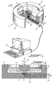
- Fig. 1 is a fragmentary perspective view of a medical apparatus for early detection and diagnosis of cartilage degeneration and constructed in accordance with a preferred embodiment of the present invention;
- Fig. 2 is a vertical cross-section view partly schematic along lines 2-2 of Fig. 1;
- Figs. 3a to 3e are graphs illustrating the value of the electrical signals measured with the apparatus of Fig. 1 and their spatial dependency;
- Figs. 4a and 4b are graphs illustrating the effect of frequency on signals measured with the apparatus of Fig. 1;
- Fig. 5 is a graph illustrating the effect of amplitude on signals measured with the apparatus of Fig. 1;
- Fig. 6 is a perspective view of another embodiment of an apparatus in accordance with the present invention;
- Fig. 7 is an enlarged end view illustrating a tip of a probe of an arthroscopic apparatus according to the other preferred embodiment of the apparatus of Fig. 6;
- Fig. 8 is a fragmentary cross-section along lines 8-8 of the tip of Fig. 7; and
- Fig. 9 is a block diagram of a signal processing module used in the apparatus comprising two electrodes.
-
- In accordance with one preferred embodiment of the present invention, there is provided a medical apparatus to detect progressive degeneration of cartilage. Fig. 1 illustrates a
medical apparatus 1 that may be used in fundamental research to follow up in vitro degeneration of cartilage. Thisapparatus 1 may also be useful in assessing integrity of cartilage before, during or after treatment of that cartilage with drugs or chemical compounds, therefore allowing evaluation of the effects of drugs or chemical compounds on the cartilage. - The
apparatus 1 illustrated in Fig. 1 comprises avessel 3 defining an enclosure having foursidewalls 5 and arigid bottom wall 7 for containing a liquid 9 therein. Anepoxy cylinder 11 containing fourelectrodes 13 is located on thebottom wall 7 at the center of thevessel 3. Theelectrodes 13 are connected to asignal conditioning module 15, which is itself connected to acomputer 17 for interpreting and analyzing the data received from themodule 15. Theapparatus 1, according to this embodiment of the invention, also comprises an actuator and aload cell 19 for applying a compression on a disk ofcartilage 21 when theload cell 19 is positioned on the disk of cartilage, thereby producing a deformation of thecartilage 21. - The
electrodes 13 areplatinum wires 12 secured through a nylon mesh producing 50µm diameter point electrodes. Theplatinum wires 12 are cast into theepoxy cylinder 11 and exposed as a linear array with a regular center-to-center distance of 380 µm (determined by the nylon mesh), covering a total distance of 1.14 mm. Thecylinder 11 containing theelectrodes 13 is fixed to thebottom wall 7 of thevessel 3. The exposed surfaces of theplatinum electrodes 13, at the surface of thebottom wall 7 are further platinized using electrochemical deposition to reduce the contact impedance of theelectrodes 13. Electrical signals from theelectrodes 13 are passed through thesignal conditioning module 15 before being received by thecomputer 17. Thevessel 3 is mounted in a micromechanical testing apparatus comprising theload cell 19 which is fixed to a precision actuator (not illustrated) for precisely positioning theload cell 19 over theelectrodes 13 at a given distance thereof, and applying, in use, a given pressure alongarrow 14 on thecartilage 21 against theelectrodes 13. - The
electrodes 13, as described above, allow for a spatial resolution of the streaming potentials of the order of 0.38 mm, allowing to produce a streaming potential map. In order to allow for such a resolution, theelectrodes 13 preferably have a diameter smaller than 500 µm and more preferably smaller than 100 µm. They may be point electrodes or circular electrodes. They could be made of other metals such as iridium or gold. - The minimal number of electrodes used in accordance with the present invention is two. When more than two electrodes are used, they may be placed in such a manner as to define more than one axis to evaluate and resolve streaming potentials spatially in more than one dimension, such as length and width for example.
- The specialized
signal conditioning module 15 is specifically designed for interfacing with theelectrodes 13. Themodule 15 is mounted in proximity to theelectrodes 13 to minimize noise pickup and microphonic effects. Thesignal conditioning module 15 may also be mounted further from the electrodes, provided that the electrodes are shielded to minimize noise pickup and microphonic effects. - Fig. 9 shows a block diagram of a module used in an apparatus comprising two electrodes. The module comprises a
voltage follower 37, a low-pass filter 39, a high-pass filter 41 and anamplifier 43. The voltage follower has a high input impedance ( »100 Mohm; 5 pF) and low bias current (<1 pAmp) to maximize rejection of common-modes of measured differential voltages between adjacent electrodes. The high input impedance of the voltage follower is required due to the relatively high impedance of the interface between the platinum wires and the electrolyte milieu. The input impedance of the first stage of the signal conditioning module must be significantly higher than this contact impedance to avoid the effect of a voltage divider. However, too high an impedance in the voltage followers leads to environmental noise pickup and microphonic effects. Therefore, a precise balance between the electrode contact impedance and the noise pickup must be struck for the signals to be acquired. A minimal distance between the electrodes and the voltage follower is preferred to minimize noise pickup. - The precision actuator may be replaced by any means, such as an electromechanical, piezoelectric or manual means, for accurately supplying a defined compressive displacement of the electrodes surface into the cartilage.
- The
computer 17 uses an analytical method of data interpretation to correlate imposed compressive displacements and measured electrical potentials to the composition and structure of the cartilage under test. This method relies on detected temporal and spatial variations of the streaming potentials across the tissue surface. A characterization of normal maps and maps typical of tissue deterioration at various degree due to osteoarthritis will indicate the degree of health or disease of an unknown tissue. - The apparatus illustrated in Figs. 1 and 2 may be used in research to evaluate effects of chemical compounds or drugs on the cartilage. To do so, pieces of normal or abnormal cartilage may be cut from humans or animal models and analyzed. The pieces may also be submitted in culture to the chemical compounds or drugs. In doing so, it is possible to identify new chemical compounds or drugs to be used for the treatment or prophylaxis of osteoarthritis.
- Another preferred embodiment is illustrated in Fig. 6. This second embodiment illustrates a
clinical apparatus 23 to evaluate human articular cartilage function during an arthroscopy. Theclinical apparatus 23 is embodied in aprobe 25 resembling a pen. Theprobe 25 is connected to thecomputer 17 for data analysis. Theprobe 25 has afree end 27 provided with a tip 27' comprisingpoint electrodes 33, anabutment surface 29 and thesignal conditioning module 35 which is embedded in the tip 27', in close proximity of theelectrodes 33. - Fig. 7 illustrates an end view of the
free end 27 and the tip 27' of theprobe 25. Sixelectrodes 33 are immobilized in an array in the tip 27'. Theabutment surface 29 illustrated in Fig. 8 is recessed compared to the tip 27'. Accordingly, theabutment surface 29 is used to create a defined compressive displacement on the cartilage. The tip 27' is applied on, and pressed against the cartilage until theabutment surface 29 rests on the cartilage. At this point, the tip 27' and the protrudingelectrodes 33 effect a compression on the cartilage inducing a streaming potential and allowing to measure and map this streaming potential. The potential measured by theelectrodes 33 is sent to thesignal conditioning module 35 which relays the data to thecomputer 17, allowing for a comparison of the map of streaming potential of the analyzed cartilage with typical maps of known healthy tissues. - Since the size of the electrode array may be on the order of I mm, the overall diameter of the
probe 25 of theclinical apparatus 23 which must be inserted into the joint can be much smaller than the arthroscopic opening (2-6 mm). The displacement of the electrodes is effected manually but precisely controlled by forcing the tip 27' into the cartilage until theabutment surface 29 stops the tip 27' from deforming the cartilage. Thus the type of applied displacement is predetermined by the step between the face of the tip and the abutment surface. The resulting electrical signals vary after the compressive force is applied as they tend to an equilibrium. The amplitude of these signals have been proven to be strongly dependent on the integrity of the cartilage by using a cytokine-mediated (interleukin-1) in vitro cartilage degradation model. - The present invention will be more readily understood by referring to the following example which is given to illustrate the invention rather than to limit its scope.
- Articular cartilage explants were isolated from a humeral head of a 1-2 year old steer. Disks of cartilage were cut from the explants. An articular cartilage disk was placed in the
vessel 3 of theapparatus 1 illustrated in Figs. 1 and 2. Thevessel 3 was filled with 0.01 M NaCl. One of theelectrodes 13 of the apparatus, located in the center of the cylinder, was placed in contact with the center of the articular disk, the other three electrodes being disposed across the first 1.14mm of the 1.5mm radius of thedisk 21. After contacting the upper surface of thedisk 21 with theload cell 19, a 240µm static compression offset was applied in a sequence of small stepped compressions. Following equilibrium, a series of dynamic sinusoidal tests was performed using frequencies in the range 0.02Hz to 2.0Hz and amplitudes in the range 0.5µm to 20µm. Ten cycles were executed for each test and harmonic analysis of the signals was performed on the last 6 cycles. - An example of the raw data obtained with the apparatus of Figs. 1 and 2 is shown in Fig. 3 for a test at a frequency of 1 Hz using a 5µm displacement amplitude. Figs. 3a to 3e illustrate the position, the load data and the differences of voltage present between three
adjacent electrodes 13 contacting thearticular disk surface 21, respectively. The voltage V1 is the streaming potential present between the center of the disk and 380µm away from that center; voltage V2 is the next incremental streaming potential from 380µm to 760µm, and V3 is another incremental streaming potential from 760µm to 1140µm. The amplitude of the incremental streaming potential V1, V2 and V3 increases from the disk center to the periphery, demonstrating the inherent spatial variation of the electric field, induced by the actuator. A streaming potential radial profile can be constructed by taking the reference potential as that of the most peripheral electrode at 1.14mm from thedisk center 21. Fig. 3 illustrates the electrical signals obtained from the apparatus and their spatial dependence. The magnitude and phase of V1, V2 and V3 in Figs. 3c to 3e depend on several factors including the geometry of the specimen, loading configuration, loading frequency and amplitude, content and distribution of charged species (aggrecan) in the tested issue, and degree of immobilization of aggrecan via entrapment in the collagen network. The ability to resolve streaming potentials on such a small spatial scale ( «lmm) is an important aspect of the invention. Using this ability allows to discriminate between the factors listed above so that specific information on the distribution and content of aggrecan, and its immobilization in the collagen network can be obtained, providing for disease diagnosis. - The amplitude and phase of the radial profile of the potential obtained with the apparatus of Figs. 1 and 2 is shown in Figs. 4a and 4b, respectively, for three different frequencies conducted at a 5µm amplitude. The reference for the potential phase is the phase of the applied axial displacement (see Fig. 3a). Figs. 4a, 4b and 5 illustrate the effects of frequency and amplitude on the measured signals for a healthy cartilage disk tested in the geometry of unconfined compression. Fig. 4a shows that the streaming potentials tend to increase in magnitude with higher frequencies. Fig. 4b shows that these streaming potentials tend to become more out of phase with the displacement at lower frequencies.
- The amplitude of the radial streaming potential profile for three different displacement amplitudes at 1 Hz is shown in Fig. 5. These are the first spatially resolved (<lmm resolution) measurements of streaming potential in loaded cartilage. Fig. 5 shows that the streaming potentials are approximately proportional to the applied displacement amplitude.
- Further data have been analyzed having altered the state of health (integrity) of the tissue by culturing cartilage disks with interleukin-1. The cell-mediated interleukin-1-induced loss of aggrecan results in greatly diminished amplitudes of the measured streaming potentials.
Claims (19)
- A medical apparatus for early detection of degradation in cartilage, said apparatus comprising:characterized in that each said electrodes are point electrodes for measuring streaming potentials in such cartilage, wherein said medical apparatus allows for spatially and temporally resolving the streaming potentials measured between said electrodes resulting from a compression applied to said cartilage.a) at least two spaced apart electrodes fixed to a solid surface and exposed for contact with a cartilage to be analyzed;b) means for compressing said electrodes and cartilage together;c) signal processing means for processing signals received from the electrodes; andd) means for analytical interpretation of data received from said signal processing means,
- The medical apparatus of claim 1, characterized in that the electrodes are made of metal wires
- The medical apparatus of claim 1, characterized in that the processing means are in close proximity to the electrodes for reducing noise pick up and microphonic effects
- The medical apparatus of claim 1, characterized in that the electrodes are made of platinum.
- The medical apparatus of claim 4, characterized in that the electrodes have a surface of platinum wire exposed to the cartilage, said exposed surface being treated to reduce electrical contact impedance.
- The medical apparatus of claim 1, characterized in that the means for processing comprises a voltage follower having a high input impedance and a low bias current to maximize rejection of common-modes of measured differential voltages between adjacent electrodes.
- The medical apparatus of claim 1, characterized in that the means for supplying a compressive displacement of the electrodes is selected from electromechanical, piezoelectric or manual means.
- The medical apparatus of claim 7, characterized in that the manual means comprise a defined abutment recessed from the electrodes for allowing said electrodes to be pressed in the cartilage until said cartilage abuts against said defined abutment.
- The medical apparatus of claim 7, characterized in that the electromechanical means comprise a precision actuator for positioning a load cell at a given height over the medical apparatus and pressing the cartilage against the electrodes.
- The medical apparatus of claim 1, characterized in that the electrodes have a diameter smaller than 500 µm.
- The medical apparatus of claim 10, characterized in that the electrodes have a diameter smaller than 100 µm.
- The medical apparatus of claim 1, characterized in that said apparatus comprising at least three electrodes, wherein said at least three electrodes define two dimensions from which data are to be analyzed.
- The medical apparatus of claim 1, characterized in that the electrodes are capable of spatially resolving streaming potentials at a resolution of about 0.38 mm.
- The medical apparatus of claim 1, characterized in that the metal wires are made of a metal selected from the group consisting of iridium, platinum and gold.
- An arthroscopic apparatus for early detection of degradation in cartilage, characterized in that said apparatus comprises:wherein said apparatus is sized and shaped to be introduced in an arthroscopic opening of about 2 to 6 mm of diameter and allows for spatially and temporally resolving the streaming potential between the electrodes.a) at least two platinum point electrodes, immobilized on a solid surface for measuring the streaming potentials of cartilage;b) an abutment surface recessed from the electrodes for allowing the electrodes to be pressed in the cartilage until said cartilage abuts against the surface;c) a front-end signal processor located in close proximity to the electrodes and comprising a voltage follower having a high input impedance and a low bias current to process signals received from the electrodes and maximize rejection of common-modes of measured differential voltages between adjacent electrodes, said processor reducing noise pick up and microphonic effects; andd) a means for analytical interpretation of data received from the processor for comparing the data received with other stored data obtained from given tissues affected by osteoarthritis at a given degree, and
- A method for detecting and mapping degradation in cartilage, in vitro, characterized in that said method comprise the steps of:wherein said at least two point electrodes allow for spatially resolving in two dimensions said streaming potentials resulting from a compression applied to said cartilage.a) applying at least two point electrodes against the cartilage;b) compressing said electrodes and cartilage together;c) measuring a streaming potential at each of said electrodes;d) analyzing and resolving the streaming potentials to obtain a map thereof; ande) interpreting said measured signals to determine the condition of the cartilage,
- The method of claim 16, characterized in that said method further comprises the step of comparing the measured signals with stored signals.
- The method of claim 16, characterized in that said step (b) comprises the steps of (i) positioning said electrodes against said cartilage, and (ii) applying a compressive force on said cartilage to press said cartilage against said electrodes.
- The method of claim 16, characterized in that said step (b) comprises the steps of (i) providing said electrodes at a tip of a probe, and (ii) pressing said tip of said probe against said cartilage.
Applications Claiming Priority (3)
| Application Number | Priority Date | Filing Date | Title |
|---|---|---|---|
| US08/796,299 US5779651A (en) | 1997-02-07 | 1997-02-07 | Medical apparatus for the diagnosis of cartilage degeneration via spatial mapping of compression-induced electrical potentials |
| US796299 | 1997-02-07 | ||
| PCT/CA1998/000084 WO1998034539A1 (en) | 1997-02-07 | 1998-02-06 | A medical device for the diagnosis of cartilage degeneration via spatial mapping of compression-induced electrical potentials |
Publications (2)
| Publication Number | Publication Date |
|---|---|
| EP0961575A1 EP0961575A1 (en) | 1999-12-08 |
| EP0961575B1 true EP0961575B1 (en) | 2004-01-14 |
Family
ID=25167858
Family Applications (1)
| Application Number | Title | Priority Date | Filing Date |
|---|---|---|---|
| EP98902884A Expired - Lifetime EP0961575B1 (en) | 1997-02-07 | 1998-02-06 | A medical device for the diagnosis of cartilage degeneration via spatial mapping of compression-induced electrical potentials |
Country Status (9)
| Country | Link |
|---|---|
| US (1) | US5779651A (en) |
| EP (1) | EP0961575B1 (en) |
| JP (1) | JP4225578B2 (en) |
| AT (1) | ATE257671T1 (en) |
| AU (1) | AU5976798A (en) |
| CA (1) | CA2278520C (en) |
| DE (1) | DE69821090T2 (en) |
| NO (1) | NO326653B1 (en) |
| WO (1) | WO1998034539A1 (en) |
Families Citing this family (33)
| Publication number | Priority date | Publication date | Assignee | Title |
|---|---|---|---|---|
| US7799077B2 (en) | 2002-10-07 | 2010-09-21 | Conformis, Inc. | Minimally invasive joint implant with 3-dimensional geometry matching the articular surfaces |
| US7468075B2 (en) | 2001-05-25 | 2008-12-23 | Conformis, Inc. | Methods and compositions for articular repair |
| US8617242B2 (en) | 2001-05-25 | 2013-12-31 | Conformis, Inc. | Implant device and method for manufacture |
| US9603711B2 (en) | 2001-05-25 | 2017-03-28 | Conformis, Inc. | Patient-adapted and improved articular implants, designs and related guide tools |
| US8882847B2 (en) | 2001-05-25 | 2014-11-11 | Conformis, Inc. | Patient selectable knee joint arthroplasty devices |
| US8480754B2 (en) | 2001-05-25 | 2013-07-09 | Conformis, Inc. | Patient-adapted and improved articular implants, designs and related guide tools |
| US8771365B2 (en) | 2009-02-25 | 2014-07-08 | Conformis, Inc. | Patient-adapted and improved orthopedic implants, designs, and related tools |
| US8735773B2 (en) | 2007-02-14 | 2014-05-27 | Conformis, Inc. | Implant device and method for manufacture |
| US8556983B2 (en) | 2001-05-25 | 2013-10-15 | Conformis, Inc. | Patient-adapted and improved orthopedic implants, designs and related tools |
| US8545569B2 (en) | 2001-05-25 | 2013-10-01 | Conformis, Inc. | Patient selectable knee arthroplasty devices |
| US7239908B1 (en) | 1998-09-14 | 2007-07-03 | The Board Of Trustees Of The Leland Stanford Junior University | Assessing the condition of a joint and devising treatment |
| DE69941304D1 (en) | 1998-09-14 | 2009-10-01 | Univ R | CONDITIONAL STATEMENT OF A JOINT AND DAMAGE |
| AU1613400A (en) * | 1998-11-10 | 2000-05-29 | Donald R. Durousseau | Fmri compatible electrode and electrode placement techniques |
| DE19929578C2 (en) * | 1999-06-21 | 2001-06-07 | Universitaetsklinikum Charite | Method and device for testing cartilage |
| WO2001008555A1 (en) * | 1999-07-29 | 2001-02-08 | Bio Syntech Canada, Inc. | Characterization of the contact distribution between two arbitrary surfaces using electrode arrays |
| US6735468B2 (en) * | 2000-02-02 | 2004-05-11 | Massachusetts Institute Of Technology | Arthroscopic impedance probe to detect cartilage degeneration |
| EP1322224B1 (en) * | 2000-09-14 | 2008-11-05 | The Board Of Trustees Of The Leland Stanford Junior University | Assessing condition of a joint and cartilage loss |
| WO2002022014A1 (en) | 2000-09-14 | 2002-03-21 | The Board Of Trustees Of The Leland Stanford Junior University | Assessing the condition of a joint and devising treatment |
| DE60136549D1 (en) | 2000-09-14 | 2008-12-24 | Univ R | METHOD FOR MANIPULATING MEDICAL IMAGES |
| JP2005504563A (en) | 2001-05-25 | 2005-02-17 | イメージング セラピューティクス,インコーポレーテッド | Methods and compositions for resurfacing joints |
| WO2004043305A1 (en) | 2002-11-07 | 2004-05-27 | Conformis, Inc. | Methods for determing meniscal size and shape and for devising treatment |
| GB0228276D0 (en) * | 2002-12-04 | 2003-01-08 | Univ Heriot Watt | Apparatus for mapping biological tissue quality |
| FR2857770B1 (en) * | 2003-07-18 | 2005-10-21 | Valois Sas | IMPROVED DOSAGE INDICATOR FOR FLUID PRODUCT DISPENSING DEVICE. |
| US7661384B2 (en) * | 2005-01-26 | 2010-02-16 | Marc J Mataya | Closure cap for a container having time-date indicators |
| WO2009105895A1 (en) * | 2008-02-29 | 2009-09-03 | Corporation De L'École Polytechnique De Montréal | Non-invasive measuring of load-induced electric potentials in diarthroidial joints |
| WO2009111626A2 (en) | 2008-03-05 | 2009-09-11 | Conformis, Inc. | Implants for altering wear patterns of articular surfaces |
| WO2009111656A1 (en) * | 2008-03-05 | 2009-09-11 | Conformis, Inc. | Edge-matched articular implant |
| JP2011519713A (en) | 2008-05-12 | 2011-07-14 | コンフォーミス・インコーポレイテッド | Devices and methods for treatment of facet joints and other joints |
| EP2405865B1 (en) | 2009-02-24 | 2019-04-17 | ConforMIS, Inc. | Automated systems for manufacturing patient-specific orthopedic implants and instrumentation |
| US20110082389A1 (en) * | 2009-10-07 | 2011-04-07 | The Regents Of The University Of California | Apparatus and method for assessing condition of articular cartilage |
| EP2509539B1 (en) | 2009-12-11 | 2020-07-01 | ConforMIS, Inc. | Patient-specific and patient-engineered orthopedic implants |
| EP2754419B1 (en) | 2011-02-15 | 2024-02-07 | ConforMIS, Inc. | Patient-adapted and improved orthopedic implants |
| US8714023B2 (en) * | 2011-03-10 | 2014-05-06 | Qualcomm Mems Technologies, Inc. | System and method for detecting surface perturbations |
Family Cites Families (5)
| Publication number | Priority date | Publication date | Assignee | Title |
|---|---|---|---|---|
| US4364399A (en) * | 1981-02-23 | 1982-12-21 | Dashefsky Joseph H | Diagnostic instrument |
| US5246013A (en) * | 1989-12-22 | 1993-09-21 | Massachusetts Institute Of Technology | Probe, system and method for detecting cartilage degeneration |
| WO1991009568A1 (en) * | 1989-12-22 | 1991-07-11 | Massachusetts Institute Of Technology | Diagnostic electromechanical spectroscopy for detection of cartilage degeneration |
| NO902883D0 (en) * | 1990-06-28 | 1990-06-28 | Bentech Subsea As | PROCEDURE AND APPARATUS FOR SEARCHING AN OBJECTS. |
| US5503162A (en) * | 1992-04-21 | 1996-04-02 | Board Of Regents, University Of Texas System | Arthroscopic cartilage evaluator and method for using the same |
-
1997
- 1997-02-07 US US08/796,299 patent/US5779651A/en not_active Expired - Lifetime
-
1998
- 1998-02-06 EP EP98902884A patent/EP0961575B1/en not_active Expired - Lifetime
- 1998-02-06 CA CA002278520A patent/CA2278520C/en not_active Expired - Fee Related
- 1998-02-06 AU AU59767/98A patent/AU5976798A/en not_active Abandoned
- 1998-02-06 WO PCT/CA1998/000084 patent/WO1998034539A1/en not_active Ceased
- 1998-02-06 AT AT98902884T patent/ATE257671T1/en not_active IP Right Cessation
- 1998-02-06 DE DE69821090T patent/DE69821090T2/en not_active Expired - Lifetime
- 1998-02-06 JP JP53346198A patent/JP4225578B2/en not_active Expired - Fee Related
-
1999
- 1999-08-06 NO NO19993819A patent/NO326653B1/en not_active IP Right Cessation
Also Published As
| Publication number | Publication date |
|---|---|
| CA2278520C (en) | 2007-07-24 |
| DE69821090T2 (en) | 2004-09-02 |
| US5779651A (en) | 1998-07-14 |
| DE69821090D1 (en) | 2004-02-19 |
| AU5976798A (en) | 1998-08-26 |
| NO993819D0 (en) | 1999-08-06 |
| CA2278520A1 (en) | 1998-08-13 |
| JP2001510370A (en) | 2001-07-31 |
| EP0961575A1 (en) | 1999-12-08 |
| NO993819L (en) | 1999-08-06 |
| ATE257671T1 (en) | 2004-01-15 |
| WO1998034539A1 (en) | 1998-08-13 |
| NO326653B1 (en) | 2009-01-26 |
| JP4225578B2 (en) | 2009-02-18 |
Similar Documents
| Publication | Publication Date | Title |
|---|---|---|
| CA2278520C (en) | A medical device for the diagnosis of cartilage degeneration via spatial mapping of compression-induced electrical potentials | |
| US6585666B2 (en) | Arthroscopic diagnostic probe to measure mechanical properties of articular cartilage | |
| US6735468B2 (en) | Arthroscopic impedance probe to detect cartilage degeneration | |
| Bell-Krotoski et al. | The force/time relationship of clinically used sensory testing instruments | |
| Blight et al. | Morphometric analysis of experimental spinal cord injury in the cat: the relation of injury intensity to survival of myelinated axons | |
| US20040092839A1 (en) | Apparatus and method for measuring local skin impedance using multiple array elecrtodes | |
| Bell-Krotoski et al. | The force/time relationship of clinically used sensory testing instruments | |
| US6010889A (en) | Electrochemical noise measurement to assess cellular behavior and metabolic activity | |
| JP2003501645A (en) | Apparatus for evaluating dynamic mechanical properties of materials | |
| CN109009105B (en) | Performance characterization method of scalp electroencephalogram sensing electrode interface material | |
| RU2399051C1 (en) | Method for estimating dynamic balance of human homeostasis stability | |
| Huang et al. | Miniaturized Water‐Jet Ultrasound Indentation System for Quantitative Assessment of Articular Cartilage Degeneration: A Validation Study | |
| EP1199983B1 (en) | Characterization of the contact distribution between two arbitrary surfaces using electrode arrays | |
| RU2206091C1 (en) | Method determining parametric characteristics of biological fluids | |
| Nabila et al. | Electrical Impedance Spectroscopic Analysis on Whole Blood Cells to Correlate Severity Level of Ischemic Stroke Patients | |
| Freund et al. | Differential diagnosis of motor disorders by tremor analysis | |
| Hastings et al. | Non-contacting electrode system for the measurement of strain generated potentials in bone | |
| WO1991009568A1 (en) | Diagnostic electromechanical spectroscopy for detection of cartilage degeneration | |
| Bombard | A surface probe for in situ detection of cartilage degradation via electromechanical spectroscopy | |
| CHOI et al. | INDENTATION TECHNIQUE FOR SIMULTANEOUS ESTIMATION OF YOUNG'S MODULUS AND POISSON'S RATIO OF SOFT TISSUES | |
| Treppo et al. | Physical diagnostics of cartilage degeneration | |
| Yang | A Stepwise Compression-Relaxation Testing Method for Tissue Characterization and Tumor Detection Via a Two-Dimensional Tactile Sensor |
Legal Events
| Date | Code | Title | Description |
|---|---|---|---|
| PUAI | Public reference made under article 153(3) epc to a published international application that has entered the european phase |
Free format text: ORIGINAL CODE: 0009012 |
|
| 17P | Request for examination filed |
Effective date: 19990810 |
|
| AK | Designated contracting states |
Kind code of ref document: A1 Designated state(s): AT BE CH DE DK ES FI FR GB GR IE IT LI LU NL PT SE |
|
| RIN1 | Information on inventor provided before grant (corrected) |
Inventor name: SAVARD, PIERRE Inventor name: LE GUYADER, PIERRE Inventor name: GARON, MARTIN Inventor name: GUARDO, ROBERT Inventor name: BUSCHMANN, MICHAEL, D. |
|
| RAP1 | Party data changed (applicant data changed or rights of an application transferred) |
Owner name: BIO SYNTECH CANADA INC. |
|
| 17Q | First examination report despatched |
Effective date: 20020912 |
|
| GRAH | Despatch of communication of intention to grant a patent |
Free format text: ORIGINAL CODE: EPIDOS IGRA |
|
| GRAS | Grant fee paid |
Free format text: ORIGINAL CODE: EPIDOSNIGR3 |
|
| GRAA | (expected) grant |
Free format text: ORIGINAL CODE: 0009210 |
|
| AK | Designated contracting states |
Kind code of ref document: B1 Designated state(s): AT BE CH DE DK ES FI FR GB GR IE IT LI LU NL PT SE |
|
| PG25 | Lapsed in a contracting state [announced via postgrant information from national office to epo] |
Ref country code: NL Free format text: LAPSE BECAUSE OF FAILURE TO SUBMIT A TRANSLATION OF THE DESCRIPTION OR TO PAY THE FEE WITHIN THE PRESCRIBED TIME-LIMIT Effective date: 20040114 Ref country code: LI Free format text: LAPSE BECAUSE OF FAILURE TO SUBMIT A TRANSLATION OF THE DESCRIPTION OR TO PAY THE FEE WITHIN THE PRESCRIBED TIME-LIMIT Effective date: 20040114 Ref country code: IT Free format text: LAPSE BECAUSE OF FAILURE TO SUBMIT A TRANSLATION OF THE DESCRIPTION OR TO PAY THE FEE WITHIN THE PRESCRIBED TIME-LIMIT;WARNING: LAPSES OF ITALIAN PATENTS WITH EFFECTIVE DATE BEFORE 2007 MAY HAVE OCCURRED AT ANY TIME BEFORE 2007. THE CORRECT EFFECTIVE DATE MAY BE DIFFERENT FROM THE ONE RECORDED. Effective date: 20040114 Ref country code: FI Free format text: LAPSE BECAUSE OF FAILURE TO SUBMIT A TRANSLATION OF THE DESCRIPTION OR TO PAY THE FEE WITHIN THE PRESCRIBED TIME-LIMIT Effective date: 20040114 Ref country code: CH Free format text: LAPSE BECAUSE OF FAILURE TO SUBMIT A TRANSLATION OF THE DESCRIPTION OR TO PAY THE FEE WITHIN THE PRESCRIBED TIME-LIMIT Effective date: 20040114 Ref country code: BE Free format text: LAPSE BECAUSE OF FAILURE TO SUBMIT A TRANSLATION OF THE DESCRIPTION OR TO PAY THE FEE WITHIN THE PRESCRIBED TIME-LIMIT Effective date: 20040114 Ref country code: AT Free format text: LAPSE BECAUSE OF FAILURE TO SUBMIT A TRANSLATION OF THE DESCRIPTION OR TO PAY THE FEE WITHIN THE PRESCRIBED TIME-LIMIT Effective date: 20040114 |
|
| REG | Reference to a national code |
Ref country code: GB Ref legal event code: FG4D |
|
| REG | Reference to a national code |
Ref country code: CH Ref legal event code: EP |
|
| PG25 | Lapsed in a contracting state [announced via postgrant information from national office to epo] |
Ref country code: LU Free format text: LAPSE BECAUSE OF NON-PAYMENT OF DUE FEES Effective date: 20040206 Ref country code: IE Free format text: LAPSE BECAUSE OF NON-PAYMENT OF DUE FEES Effective date: 20040206 |
|
| REG | Reference to a national code |
Ref country code: IE Ref legal event code: FG4D |
|
| REF | Corresponds to: |
Ref document number: 69821090 Country of ref document: DE Date of ref document: 20040219 Kind code of ref document: P |
|
| PG25 | Lapsed in a contracting state [announced via postgrant information from national office to epo] |
Ref country code: SE Free format text: LAPSE BECAUSE OF FAILURE TO SUBMIT A TRANSLATION OF THE DESCRIPTION OR TO PAY THE FEE WITHIN THE PRESCRIBED TIME-LIMIT Effective date: 20040414 Ref country code: GR Free format text: LAPSE BECAUSE OF FAILURE TO SUBMIT A TRANSLATION OF THE DESCRIPTION OR TO PAY THE FEE WITHIN THE PRESCRIBED TIME-LIMIT Effective date: 20040414 Ref country code: DK Free format text: LAPSE BECAUSE OF FAILURE TO SUBMIT A TRANSLATION OF THE DESCRIPTION OR TO PAY THE FEE WITHIN THE PRESCRIBED TIME-LIMIT Effective date: 20040414 |
|
| PG25 | Lapsed in a contracting state [announced via postgrant information from national office to epo] |
Ref country code: ES Free format text: LAPSE BECAUSE OF FAILURE TO SUBMIT A TRANSLATION OF THE DESCRIPTION OR TO PAY THE FEE WITHIN THE PRESCRIBED TIME-LIMIT Effective date: 20040425 |
|
| NLV1 | Nl: lapsed or annulled due to failure to fulfill the requirements of art. 29p and 29m of the patents act | ||
| REG | Reference to a national code |
Ref country code: CH Ref legal event code: PL |
|
| ET | Fr: translation filed | ||
| REG | Reference to a national code |
Ref country code: IE Ref legal event code: MM4A |
|
| PLBE | No opposition filed within time limit |
Free format text: ORIGINAL CODE: 0009261 |
|
| STAA | Information on the status of an ep patent application or granted ep patent |
Free format text: STATUS: NO OPPOSITION FILED WITHIN TIME LIMIT |
|
| 26N | No opposition filed |
Effective date: 20041015 |
|
| PG25 | Lapsed in a contracting state [announced via postgrant information from national office to epo] |
Ref country code: PT Free format text: LAPSE BECAUSE OF NON-PAYMENT OF DUE FEES Effective date: 20040614 |
|
| PGFP | Annual fee paid to national office [announced via postgrant information from national office to epo] |
Ref country code: FR Payment date: 20100914 Year of fee payment: 13 |
|
| REG | Reference to a national code |
Ref country code: FR Ref legal event code: TP |
|
| REG | Reference to a national code |
Ref country code: GB Ref legal event code: 732E Free format text: REGISTERED BETWEEN 20110303 AND 20110309 |
|
| REG | Reference to a national code |
Ref country code: DE Ref legal event code: R081 Ref document number: 69821090 Country of ref document: DE Owner name: BIOMOMENTUM INC., LAVAL, CA Free format text: FORMER OWNER: BIO SYNTECH CANADA INC., LAVAL, QUEBEC, CA Effective date: 20110907 Ref country code: DE Ref legal event code: R081 Ref document number: 69821090 Country of ref document: DE Owner name: BIOMOMENTUM INC., CA Free format text: FORMER OWNER: BIO SYNTECH CANADA INC., LAVAL, CA Effective date: 20110907 |
|
| REG | Reference to a national code |
Ref country code: GB Ref legal event code: 732E Free format text: REGISTERED BETWEEN 20111013 AND 20111019 |
|
| REG | Reference to a national code |
Ref country code: FR Ref legal event code: ST Effective date: 20111102 |
|
| PG25 | Lapsed in a contracting state [announced via postgrant information from national office to epo] |
Ref country code: FR Free format text: LAPSE BECAUSE OF NON-PAYMENT OF DUE FEES Effective date: 20110228 |
|
| REG | Reference to a national code |
Ref country code: DE Ref legal event code: R082 Ref document number: 69821090 Country of ref document: DE Representative=s name: BOCKHORNI & KOLLEGEN, DE |
|
| REG | Reference to a national code |
Ref country code: DE Ref legal event code: R082 Ref document number: 69821090 Country of ref document: DE Representative=s name: BOCKHORNI & KOLLEGEN PATENT- UND RECHTSANWAELT, DE Effective date: 20120627 Ref country code: DE Ref legal event code: R081 Ref document number: 69821090 Country of ref document: DE Owner name: BIOMOMENTUM INC., LAVAL, CA Free format text: FORMER OWNER: PIRAMAL HEALTHCARE (CANADA) LTD., AURORA, CA Effective date: 20120627 Ref country code: DE Ref legal event code: R081 Ref document number: 69821090 Country of ref document: DE Owner name: BIOMOMENTUM INC., CA Free format text: FORMER OWNER: PIRAMAL HEALTHCARE (CANADA) LTD., AURORA, CA Effective date: 20120627 |
|
| REG | Reference to a national code |
Ref country code: DE Ref legal event code: R119 Ref document number: 69821090 Country of ref document: DE Effective date: 20130903 |
|
| PG25 | Lapsed in a contracting state [announced via postgrant information from national office to epo] |
Ref country code: DE Free format text: LAPSE BECAUSE OF NON-PAYMENT OF DUE FEES Effective date: 20130903 |
|
| REG | Reference to a national code |
Ref country code: DE Ref legal event code: R073 Ref document number: 69821090 Country of ref document: DE |
|
| REG | Reference to a national code |
Ref country code: DE Ref legal event code: R074 Ref document number: 69821090 Country of ref document: DE |
|
| PGFP | Annual fee paid to national office [announced via postgrant information from national office to epo] |
Ref country code: GB Payment date: 20140206 Year of fee payment: 17 |
|
| REG | Reference to a national code |
Ref country code: DE Ref legal event code: R074 Ref document number: 69821090 Country of ref document: DE Effective date: 20140531 |
|
| PGRI | Patent reinstated in contracting state [announced from national office to epo] |
Ref country code: DE Effective date: 20140528 |
|
| PGFP | Annual fee paid to national office [announced via postgrant information from national office to epo] |
Ref country code: DE Payment date: 20140704 Year of fee payment: 17 |
|
| REG | Reference to a national code |
Ref country code: DE Ref legal event code: R119 Ref document number: 69821090 Country of ref document: DE |
|
| GBPC | Gb: european patent ceased through non-payment of renewal fee |
Effective date: 20150206 |
|
| PG25 | Lapsed in a contracting state [announced via postgrant information from national office to epo] |
Ref country code: GB Free format text: LAPSE BECAUSE OF NON-PAYMENT OF DUE FEES Effective date: 20150206 |
|
| PG25 | Lapsed in a contracting state [announced via postgrant information from national office to epo] |
Ref country code: DE Free format text: LAPSE BECAUSE OF NON-PAYMENT OF DUE FEES Effective date: 20150901 |
|
| REG | Reference to a national code |
Ref country code: DE Ref legal event code: R082 Ref document number: 69821090 Country of ref document: DE Representative=s name: DOMPATENT VON KREISLER SELTING WERNER - PARTNE, DE |