EP0961366B1 - Halter für nachgiebige End-Steckerstifte - Google Patents
Halter für nachgiebige End-Steckerstifte Download PDFInfo
- Publication number
- EP0961366B1 EP0961366B1 EP99303915A EP99303915A EP0961366B1 EP 0961366 B1 EP0961366 B1 EP 0961366B1 EP 99303915 A EP99303915 A EP 99303915A EP 99303915 A EP99303915 A EP 99303915A EP 0961366 B1 EP0961366 B1 EP 0961366B1
- Authority
- EP
- European Patent Office
- Prior art keywords
- terminals
- insert
- insulative member
- terminal
- exposed portions
- Prior art date
- Legal status (The legal status is an assumption and is not a legal conclusion. Google has not performed a legal analysis and makes no representation as to the accuracy of the status listed.)
- Expired - Lifetime
Links
- 230000013011 mating Effects 0.000 claims description 7
- 230000014759 maintenance of location Effects 0.000 description 4
- 239000000463 material Substances 0.000 description 2
- 238000005476 soldering Methods 0.000 description 2
- 230000007704 transition Effects 0.000 description 2
- 230000037431 insertion Effects 0.000 description 1
- 238000003780 insertion Methods 0.000 description 1
- 230000006641 stabilisation Effects 0.000 description 1
- 238000011105 stabilization Methods 0.000 description 1
Images
Classifications
-
- H—ELECTRICITY
- H01—ELECTRIC ELEMENTS
- H01R—ELECTRICALLY-CONDUCTIVE CONNECTIONS; STRUCTURAL ASSOCIATIONS OF A PLURALITY OF MUTUALLY-INSULATED ELECTRICAL CONNECTING ELEMENTS; COUPLING DEVICES; CURRENT COLLECTORS
- H01R13/00—Details of coupling devices of the kinds covered by groups H01R12/70 or H01R24/00 - H01R33/00
- H01R13/46—Bases; Cases
- H01R13/502—Bases; Cases composed of different pieces
- H01R13/506—Bases; Cases composed of different pieces assembled by snap action of the parts
-
- H—ELECTRICITY
- H01—ELECTRIC ELEMENTS
- H01R—ELECTRICALLY-CONDUCTIVE CONNECTIONS; STRUCTURAL ASSOCIATIONS OF A PLURALITY OF MUTUALLY-INSULATED ELECTRICAL CONNECTING ELEMENTS; COUPLING DEVICES; CURRENT COLLECTORS
- H01R12/00—Structural associations of a plurality of mutually-insulated electrical connecting elements, specially adapted for printed circuits, e.g. printed circuit boards [PCB], flat or ribbon cables, or like generally planar structures, e.g. terminal strips, terminal blocks; Coupling devices specially adapted for printed circuits, flat or ribbon cables, or like generally planar structures; Terminals specially adapted for contact with, or insertion into, printed circuits, flat or ribbon cables, or like generally planar structures
- H01R12/70—Coupling devices
- H01R12/71—Coupling devices for rigid printing circuits or like structures
- H01R12/712—Coupling devices for rigid printing circuits or like structures co-operating with the surface of the printed circuit or with a coupling device exclusively provided on the surface of the printed circuit
- H01R12/716—Coupling device provided on the PCB
-
- H—ELECTRICITY
- H01—ELECTRIC ELEMENTS
- H01R—ELECTRICALLY-CONDUCTIVE CONNECTIONS; STRUCTURAL ASSOCIATIONS OF A PLURALITY OF MUTUALLY-INSULATED ELECTRICAL CONNECTING ELEMENTS; COUPLING DEVICES; CURRENT COLLECTORS
- H01R12/00—Structural associations of a plurality of mutually-insulated electrical connecting elements, specially adapted for printed circuits, e.g. printed circuit boards [PCB], flat or ribbon cables, or like generally planar structures, e.g. terminal strips, terminal blocks; Coupling devices specially adapted for printed circuits, flat or ribbon cables, or like generally planar structures; Terminals specially adapted for contact with, or insertion into, printed circuits, flat or ribbon cables, or like generally planar structures
- H01R12/70—Coupling devices
- H01R12/71—Coupling devices for rigid printing circuits or like structures
- H01R12/72—Coupling devices for rigid printing circuits or like structures coupling with the edge of the rigid printed circuits or like structures
- H01R12/722—Coupling devices for rigid printing circuits or like structures coupling with the edge of the rigid printed circuits or like structures coupling devices mounted on the edge of the printed circuits
- H01R12/724—Coupling devices for rigid printing circuits or like structures coupling with the edge of the rigid printed circuits or like structures coupling devices mounted on the edge of the printed circuits containing contact members forming a right angle
-
- H—ELECTRICITY
- H01—ELECTRIC ELEMENTS
- H01R—ELECTRICALLY-CONDUCTIVE CONNECTIONS; STRUCTURAL ASSOCIATIONS OF A PLURALITY OF MUTUALLY-INSULATED ELECTRICAL CONNECTING ELEMENTS; COUPLING DEVICES; CURRENT COLLECTORS
- H01R24/00—Two-part coupling devices, or either of their cooperating parts, characterised by their overall structure
- H01R24/60—Contacts spaced along planar side wall transverse to longitudinal axis of engagement
- H01R24/62—Sliding engagements with one side only, e.g. modular jack coupling devices
- H01R24/64—Sliding engagements with one side only, e.g. modular jack coupling devices for high frequency, e.g. RJ 45
-
- H—ELECTRICITY
- H01—ELECTRIC ELEMENTS
- H01R—ELECTRICALLY-CONDUCTIVE CONNECTIONS; STRUCTURAL ASSOCIATIONS OF A PLURALITY OF MUTUALLY-INSULATED ELECTRICAL CONNECTING ELEMENTS; COUPLING DEVICES; CURRENT COLLECTORS
- H01R25/00—Coupling parts adapted for simultaneous co-operation with two or more identical counterparts, e.g. for distributing energy to two or more circuits
- H01R25/006—Coupling parts adapted for simultaneous co-operation with two or more identical counterparts, e.g. for distributing energy to two or more circuits the coupling part being secured to apparatus or structure, e.g. duplex wall receptacle
Definitions
- the invention relates to terminal inserts for an electrical connector wherein the inserts include terminals with compliant pins which are insertable into holes in a circuit board.
- U.S. Patent No. 5,531,612 discloses an electrical connector of a type known as a stacked modular jack which comprises a plurality of modular jacks that are arranged in two rows in one unit.
- Each of the modular jacks comprises an insert which includes terminals carried by a plastic member.
- Each of the terminals has a circuit board engaging portion in the form of a lead that can be inserted into a through-hole in a circuit board for electrical attachment to the circuit board by soldering. It is now proposed to provide a stacked modular jack with leads in the form of compliant pins which are interference fitted in the through-holes for retention of the leads to the circuit board without soldering.
- a problem with compliant pin leads is that they must be urged into their respective through-holes with a force which may cause buckling of the terminals in the vicinity of the compliant pins. Therefore, the terminals must be robust to resist buckling and/or the terminals must be firmly supported to prevent buckling.
- the terminals are substantially surrounded by plastic adjacent to the compliant pin leads.
- this causes a problem in that the terminals are not fully supported at the back of the insert, and terminals having compliant pin leads may be subject to buckling. This problem is solved by a device according to claim 1.
- a further prior art stacked modular jack electrical connector (on which the preamble of claim 1 is based) is disclosed in US Patent No. 5,639,267 .
- the connector includes upper and lower terminal inserts each of which includes an insulated number in which a plurality of contact pins are embedded. Part of each pin extends down a pin guide in a rear face of the insulated member and alternate pin guides comprise slots in the respective insulative member.
- An L-shaped shield plate separates the upper terminal inserts from the lower terminal inserts.
- a backplate member is provided with a first row of strips which project into the slots in the lower terminal inserts and a corresponding second row of strips for the upper terminal inserts.
- the invention is an insert subassembly for an electrical connector comprising a lower terminal insert and an upper terminal insert.
- the lower terminal insert includes a lower insulative member which carries terminals that have exposed portions at a rear of the lower insulative member. The exposed portions extend downwardly to define leads for the connector.
- the upper terminal insert includes an upper insulative member which carries terminals, and the upper insulative member has support surfaces which confront the exposed portions of the terminals of the lower terminal insert to provide support for the exposed portions when the leads are engaged with a circuit board.
- the stacked modular jack comprises a housing having a plurality of modular jack receptacles each of which can receive a mating modular plug.
- the receptacles are arranged in two rows which can be termed an upper row and a lower row. Extending into each of the receptacles is an array of terminals that are arranged in accordance with an industry standard configuration such as for an RJll or RJ45 style modular jack.
- Each terminal array is separately formed as a terminal insert which can be installed in the housing.
- Each terminal insert includes an insulative member which holds a plurality of terminals in the fixed array.
- the terminal inserts are either upper terminal inserts or lower terminal inserts which correspond to the upper and lower receptacles, respectively.
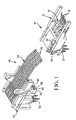
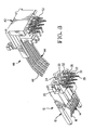
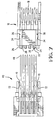
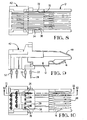
- the terminal insert subassembly 4 comprises a lower terminal insert 10 and an upper terminal insert 40, as shown in Figs. 1 and 3 .
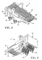
- the lower terminal insert 10 includes a lower insulative member 12 and a plurality of terminals 14.
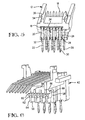
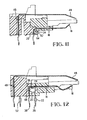
- Each of the terminals has a horizontally extending retention section 16 (shown in Figs. 11 and 12 ) which is secured in the lower insulative member, a forward mating section 18 which is engageable with a terminal of a mating modular plug, and a downward section 20 which terminates in a compliant pin lead 22 that is resiliently insertable in a through-hole in a circuit board (not shown) for electrical and mechanical engagement with the circuit board.
- a bend section 24 transitions between the retention section 16 and the downward section 20. Exposed portions of the terminals at the rear of the lower insulative member include the downward sections 20 and the bend sections 24. The exposed portions are defined by a lack of insulative material on at least one side of the terminals. The absence of material surrounding the terminals at the rear of the lower insulative member minimizes the size and cost of the lower insulative member.
- the lower insulative member has a series of support bars 26 and slots 28 between the support bars.
- the downward sections 20 of the terminals are arranged in two lateral terminal rows 29, 30.
- the downward sections in the terminal row 29 are disposed in the slots 28, and the downward sections in the terminal row 30 are disposed in notches 32 in the ends of the support bars 26.
- the slots 28 and the notches 32 help to align, stabilize and support the downward sections of the terminals which are exposed at the rear of the lower insulative member. Further stabilization and support for the exposed portions of the terminals is provided by the upper terminal insert 40 as will be described.
- the upper terminal insert 40 includes an upper insulative member 42 and a plurality of terminals 44.
- Each of the terminals has a vertically extending retention section 46 (shown in Figs. 11 and 12 ) which is secured in the upper insulative member.
- Each of the terminals extends horizontally to a forward mating section 48 which is engageable with a terminal of a mating modular plug.
- An opposite end of each terminal includes a compliant pin lead 52 for electrical and mechanical engagement with a circuit board.
- a forward portion of the upper insulative member provides support surfaces which are configured to confront the exposed portions of the terminals at the rear of the lower terminal insert.
- the upper insulative member has an array of forwardly extending ribs 56 and inwardly extending grooves 58.
- the ribs 56 are configured to fit in the slots 28 between the support bars 26 of the lower insulative member.
- Extending from each rib 56 is a projection 60 having a curvilinear undersurface 62 which transitions to a front surface 64 of the rib 56.
- the undersurfaces 62 and the front surfaces 64 are configured to closely confront the exposed portions of the terminals in the terminal row 29.
- the undersurfaces 62 and the front surfaces 64 serve as support surfaces for the exposed portions of the terminals in the terminal row 29 when the compliant pin leads 22 of these terminals are installed in a circuit board. Further, the exposed portions of the terminals in the terminal row 30 are received in the grooves 58. A downwardly facing surface 66 and a forwardly facing surface 68 within each of the grooves serve as support surfaces for the exposed portions of the terminals in the terminal row 30.
- the upper terminal insert 40 has ramps 70 and rearwardly facing latches 72.
- the lower terminal insert 10 has ramps 34 and forwardly facing latches 36.
- the latches 36 and 72 cooperate to secure the upper and lower terminal inserts together in a latched condition.
- the support surfaces 62, 64, 66, 68 closely confront the bend sections 24 and the downward sections 20 which are exposed at the rear of the lower terminal insert.
- the support surfaces 62, 64, 66, 68 may either be in contact with the exposed portions of the terminals or spaced from the exposed portions by a small clearance. If the support surfaces are spaced from the exposed portions, the exposed portions will be deflected into engagement with the support surfaces during insertion of the compliant pins into holes in a circuit board.
- the support surfaces provide support and stability for the exposed portions of the terminals when the compliant pins are urged into the circuit board holes.
Landscapes
- Coupling Device And Connection With Printed Circuit (AREA)
- Multi-Conductor Connections (AREA)
- Manufacturing Of Electrical Connectors (AREA)
Claims (6)
- Einsatz-Unterbaugruppe (4) für einen elektrischen Steckverbinder, die einen unteren Anschlusseinsatz (10) einschließlich eines unteren isolierenden Elements (12), das Anschlüsse (14) trägt, die freigelegte Abschnitte (20, 24) an der Rückseite des unteren isolierenden Elements haben, wobei sich die freigelegten Abschnitte nach unten erstrecken, um Leitungen (22) für den Steckverbinder zu definieren, und einen oberen Anschlusseinsatz (40) einschließlich eines oberen isolierenden Elements (42), das Anschlüsse (44) trägt, umfasst,
dadurch gekennzeichnet, dass das obere isolierende Element (42) Stützflächen (62, 64, 66, 68) hat, die den freigelegten Abschnitten (20, 24) der Anschlüsse des unteren isolierenden Elements gegenüberstehen, um eine Stütze für die freigelegten Abschnitte bereitzustellen, wenn die Leitungen mit einer Leiterplatte in Eingriff gebracht werden. - Einsatz-Unterbaugruppe nach Anspruch 1, wobei das obere isolierende Element (42) sich nach vorn erstreckende Rippen (56) einschließt und die Stützflächen (64) durch Vorderseiten der sich nach vorn erstreckenden Rippen definiert werden.
- Einsatz-Unterbaugruppe nach Anspruch 1 oder 2, wobei das obere isolierende Element (42) sich nach vorn erstreckende Vorsprünge (60) einschließt und die Stützflächen (62) durch Unterseiten der sich nach vorn erstreckenden Vorsprünge definiert werden.
- Einsatz-Unterbaugruppe nach einem der Ansprüche 1, 2 oder 3, wobei das obere isolierende Element Rillen (58) zwischen sich nach vorn erstreckenden Rippen (56) einschließt und die Stützflächen (66, 68) durch Wandflächen innerhalb jeder der Rillen definiert werden.
- Einsatz-Unterbaugruppe nach einem der vorhergehenden Ansprüche, wobei der untere Anschlusseinsatz und der obere Anschlusseinsatz Klinken (36, 72) haben, die wechselseitig zusammenwirken können.
- Einsatz-Unterbaugruppe nach einem der vorhergehenden Ansprüche, wobei das eine Ende der Anschlüsse (44) des oberen isolierenden Elements vordere Stecksektionen (48) für einen Eingriff mit einem Anschluss eines modularen Gegensteckers einschließt und das andere Ende der Anschlüsse (44) Leitungen für einen Eingriff mit einer Leiterplatte einschließt.
Applications Claiming Priority (2)
| Application Number | Priority Date | Filing Date | Title |
|---|---|---|---|
| US86733 | 1998-05-29 | ||
| US09/086,733 US6042393A (en) | 1998-05-29 | 1998-05-29 | Support for compliant pin terminals |
Publications (3)
| Publication Number | Publication Date |
|---|---|
| EP0961366A2 EP0961366A2 (de) | 1999-12-01 |
| EP0961366A3 EP0961366A3 (de) | 2001-09-12 |
| EP0961366B1 true EP0961366B1 (de) | 2008-08-06 |
Family
ID=22200533
Family Applications (1)
| Application Number | Title | Priority Date | Filing Date |
|---|---|---|---|
| EP99303915A Expired - Lifetime EP0961366B1 (de) | 1998-05-29 | 1999-05-20 | Halter für nachgiebige End-Steckerstifte |
Country Status (3)
| Country | Link |
|---|---|
| US (1) | US6042393A (de) |
| EP (1) | EP0961366B1 (de) |
| CN (1) | CN1238578A (de) |
Families Citing this family (3)
| Publication number | Priority date | Publication date | Assignee | Title |
|---|---|---|---|---|
| US6042393A (en) * | 1998-05-29 | 2000-03-28 | The Whitaker Corporation | Support for compliant pin terminals |
| US7458274B2 (en) * | 2007-02-20 | 2008-12-02 | Honeywell International Inc. | Pressure sensor incorporating a compliant pin |
| FR3064826B1 (fr) * | 2017-03-29 | 2020-10-09 | Tyco Electronics France Sas | Ensemble de support pour broches de contact a ajustement par pression |
Family Cites Families (9)
| Publication number | Priority date | Publication date | Assignee | Title |
|---|---|---|---|---|
| US4469387A (en) * | 1982-08-23 | 1984-09-04 | Amp Incorporated | Printed circuit board connector |
| US4857017A (en) * | 1987-04-24 | 1989-08-15 | Maxconn, Inc. | Support device for wires in multi-contact connectors |
| GB2271678B (en) * | 1993-12-03 | 1994-10-12 | Itt Ind Ltd | Electrical connector |
| GB9325594D0 (en) * | 1993-12-14 | 1994-02-16 | Amp Great Britain | Multi-port modular jack assembly |
| US5419720A (en) * | 1994-03-16 | 1995-05-30 | Chen; Michael | Structure of jack for modular plugs |
| US5562507A (en) * | 1994-11-25 | 1996-10-08 | Kan; Bright | Two-layer type multi-wire connection socket structure |
| US5599209A (en) * | 1994-11-30 | 1997-02-04 | Berg Technology, Inc. | Method of reducing electrical crosstalk and common mode electromagnetic interference and modular jack for use therein |
| US5639267A (en) * | 1996-01-26 | 1997-06-17 | Maxconn Incorporated | Modular jack assembly |
| US6042393A (en) * | 1998-05-29 | 2000-03-28 | The Whitaker Corporation | Support for compliant pin terminals |
-
1998
- 1998-05-29 US US09/086,733 patent/US6042393A/en not_active Expired - Lifetime
-
1999
- 1999-05-20 EP EP99303915A patent/EP0961366B1/de not_active Expired - Lifetime
- 1999-05-28 CN CN99106956A patent/CN1238578A/zh active Pending
Also Published As
| Publication number | Publication date |
|---|---|
| EP0961366A2 (de) | 1999-12-01 |
| EP0961366A3 (de) | 2001-09-12 |
| CN1238578A (zh) | 1999-12-15 |
| US6042393A (en) | 2000-03-28 |
Similar Documents
| Publication | Publication Date | Title |
|---|---|---|
| EP0880808B1 (de) | Abgeschimter elektrischer verbinder | |
| US6379187B2 (en) | Electrical connector | |
| US6319070B1 (en) | RJ-receptacle connector with anti-mismating device | |
| US6120318A (en) | Stacked electrical connector having visual indicator subassembly | |
| EP0306523B1 (de) | System zur ausrichtung und arretierung von lötstiften | |
| US6416364B1 (en) | RJ-45 receptacle connector with terminal protection means | |
| US5674078A (en) | Multi-directional interface header assembly | |
| EP0795929A2 (de) | Elektrische Verbinderanordnung mit verbessertem Haltemittelcharakteristik | |
| EP0488298B1 (de) | Verbinder mit Kontaktdistanzierplatte mit gleichförmiger seitlicher Kraft | |
| US6200161B1 (en) | Stacked electrical connector | |
| US5993263A (en) | Reduced mating force electrical connector | |
| JPH0797507B2 (ja) | モジュラープラグ用ジヤツク | |
| US7217158B2 (en) | Electrical connector | |
| US5080596A (en) | Connector with contact spacer plate providing greater lateral force on rear contacts | |
| WO1986001946A1 (en) | Double row electrical connector | |
| EP0784359A1 (de) | Elektrischer Verbinder mit Anschlussmodulen und Ausrichtungsvorrichtung für Anschlussenden | |
| US6935900B2 (en) | Modular jack having an anti-mismating member to prevent incorrect insertion of a smaller sized plug | |
| EP0996993B1 (de) | Verriegelte und abgeschirmte elektrische verbinder | |
| US5947754A (en) | Electrical connecting to a printed circuit board | |
| EP0488349B1 (de) | Verbinder mit Kontaktabstandsplatte mit keilförmigen Kanälen | |
| US6767224B2 (en) | Electrical connector with improved terminal retaining system | |
| US6162068A (en) | Electrical connector assembly | |
| CN112636044B (zh) | 连接器 | |
| US6042393A (en) | Support for compliant pin terminals | |
| US6780063B2 (en) | Wire connected modular jack and assembling method |
Legal Events
| Date | Code | Title | Description |
|---|---|---|---|
| PUAI | Public reference made under article 153(3) epc to a published international application that has entered the european phase |
Free format text: ORIGINAL CODE: 0009012 |
|
| AK | Designated contracting states |
Kind code of ref document: A2 Designated state(s): AT BE CH CY DE DK ES FI FR GB GR IE IT LI LU MC NL PT SE Kind code of ref document: A2 Designated state(s): DE FR GB IE IT NL SE |
|
| AX | Request for extension of the european patent |
Free format text: AL;LT;LV;MK;RO;SI |
|
| PUAL | Search report despatched |
Free format text: ORIGINAL CODE: 0009013 |
|
| AK | Designated contracting states |
Kind code of ref document: A3 Designated state(s): AT BE CH CY DE DK ES FI FR GB GR IE IT LI LU MC NL PT SE |
|
| AX | Request for extension of the european patent |
Free format text: AL;LT;LV;MK;RO;SI |
|
| 17P | Request for examination filed |
Effective date: 20020308 |
|
| AKX | Designation fees paid |
Free format text: DE FR GB IE IT NL SE |
|
| 17Q | First examination report despatched |
Effective date: 20070606 |
|
| GRAP | Despatch of communication of intention to grant a patent |
Free format text: ORIGINAL CODE: EPIDOSNIGR1 |
|
| GRAS | Grant fee paid |
Free format text: ORIGINAL CODE: EPIDOSNIGR3 |
|
| GRAA | (expected) grant |
Free format text: ORIGINAL CODE: 0009210 |
|
| RIC1 | Information provided on ipc code assigned before grant |
Ipc: H01R 24/06 20060101AFI20080624BHEP |
|
| AK | Designated contracting states |
Kind code of ref document: B1 Designated state(s): DE FR GB IE IT NL SE |
|
| REG | Reference to a national code |
Ref country code: GB Ref legal event code: FG4D |
|
| REG | Reference to a national code |
Ref country code: IE Ref legal event code: FG4D |
|
| REF | Corresponds to: |
Ref document number: 69939235 Country of ref document: DE Date of ref document: 20080918 Kind code of ref document: P |
|
| PG25 | Lapsed in a contracting state [announced via postgrant information from national office to epo] |
Ref country code: NL Free format text: LAPSE BECAUSE OF FAILURE TO SUBMIT A TRANSLATION OF THE DESCRIPTION OR TO PAY THE FEE WITHIN THE PRESCRIBED TIME-LIMIT Effective date: 20080806 |
|
| PLBE | No opposition filed within time limit |
Free format text: ORIGINAL CODE: 0009261 |
|
| STAA | Information on the status of an ep patent application or granted ep patent |
Free format text: STATUS: NO OPPOSITION FILED WITHIN TIME LIMIT |
|
| 26N | No opposition filed |
Effective date: 20090507 |
|
| PG25 | Lapsed in a contracting state [announced via postgrant information from national office to epo] |
Ref country code: IT Free format text: LAPSE BECAUSE OF FAILURE TO SUBMIT A TRANSLATION OF THE DESCRIPTION OR TO PAY THE FEE WITHIN THE PRESCRIBED TIME-LIMIT Effective date: 20080806 |
|
| PG25 | Lapsed in a contracting state [announced via postgrant information from national office to epo] |
Ref country code: SE Free format text: LAPSE BECAUSE OF FAILURE TO SUBMIT A TRANSLATION OF THE DESCRIPTION OR TO PAY THE FEE WITHIN THE PRESCRIBED TIME-LIMIT Effective date: 20081106 |
|
| REG | Reference to a national code |
Ref country code: IE Ref legal event code: MM4A |
|
| PG25 | Lapsed in a contracting state [announced via postgrant information from national office to epo] |
Ref country code: IE Free format text: LAPSE BECAUSE OF NON-PAYMENT OF DUE FEES Effective date: 20090520 |
|
| REG | Reference to a national code |
Ref country code: FR Ref legal event code: PLFP Year of fee payment: 18 |
|
| REG | Reference to a national code |
Ref country code: FR Ref legal event code: PLFP Year of fee payment: 19 |
|
| REG | Reference to a national code |
Ref country code: FR Ref legal event code: PLFP Year of fee payment: 20 |
|
| PGFP | Annual fee paid to national office [announced via postgrant information from national office to epo] |
Ref country code: DE Payment date: 20180508 Year of fee payment: 20 |
|
| PGFP | Annual fee paid to national office [announced via postgrant information from national office to epo] |
Ref country code: FR Payment date: 20180411 Year of fee payment: 20 |
|
| PGFP | Annual fee paid to national office [announced via postgrant information from national office to epo] |
Ref country code: GB Payment date: 20180516 Year of fee payment: 20 |
|
| REG | Reference to a national code |
Ref country code: DE Ref legal event code: R071 Ref document number: 69939235 Country of ref document: DE |
|
| REG | Reference to a national code |
Ref country code: GB Ref legal event code: PE20 Expiry date: 20190519 |
|
| PG25 | Lapsed in a contracting state [announced via postgrant information from national office to epo] |
Ref country code: GB Free format text: LAPSE BECAUSE OF EXPIRATION OF PROTECTION Effective date: 20190519 |