EP0961352A1 - Multi-pin connector for flat cable - Google Patents
Multi-pin connector for flat cable Download PDFInfo
- Publication number
- EP0961352A1 EP0961352A1 EP99201673A EP99201673A EP0961352A1 EP 0961352 A1 EP0961352 A1 EP 0961352A1 EP 99201673 A EP99201673 A EP 99201673A EP 99201673 A EP99201673 A EP 99201673A EP 0961352 A1 EP0961352 A1 EP 0961352A1
- Authority
- EP
- European Patent Office
- Prior art keywords
- pin
- contact arms
- connector
- terminals
- insulative housing
- Prior art date
- Legal status (The legal status is an assumption and is not a legal conclusion. Google has not performed a legal analysis and makes no representation as to the accuracy of the status listed.)
- Granted
Links
- 238000004891 communication Methods 0.000 claims description 2
- 238000003780 insertion Methods 0.000 abstract description 9
- 230000037431 insertion Effects 0.000 abstract description 9
- 238000005516 engineering process Methods 0.000 description 4
- 238000005476 soldering Methods 0.000 description 4
- 239000004020 conductor Substances 0.000 description 3
- 229910000679 solder Inorganic materials 0.000 description 3
- 239000000463 material Substances 0.000 description 2
- 238000000034 method Methods 0.000 description 2
- 230000008569 process Effects 0.000 description 2
- LQBJWKCYZGMFEV-UHFFFAOYSA-N lead tin Chemical compound [Sn].[Pb] LQBJWKCYZGMFEV-UHFFFAOYSA-N 0.000 description 1
- 230000007246 mechanism Effects 0.000 description 1
- 239000007769 metal material Substances 0.000 description 1
- 238000012986 modification Methods 0.000 description 1
- 230000004048 modification Effects 0.000 description 1
- 230000008685 targeting Effects 0.000 description 1
Images


Classifications
-
- H—ELECTRICITY
- H01—ELECTRIC ELEMENTS
- H01R—ELECTRICALLY-CONDUCTIVE CONNECTIONS; STRUCTURAL ASSOCIATIONS OF A PLURALITY OF MUTUALLY-INSULATED ELECTRICAL CONNECTING ELEMENTS; COUPLING DEVICES; CURRENT COLLECTORS
- H01R12/00—Structural associations of a plurality of mutually-insulated electrical connecting elements, specially adapted for printed circuits, e.g. printed circuit boards [PCB], flat or ribbon cables, or like generally planar structures, e.g. terminal strips, terminal blocks; Coupling devices specially adapted for printed circuits, flat or ribbon cables, or like generally planar structures; Terminals specially adapted for contact with, or insertion into, printed circuits, flat or ribbon cables, or like generally planar structures
- H01R12/70—Coupling devices
- H01R12/82—Coupling devices connected with low or zero insertion force
- H01R12/85—Coupling devices connected with low or zero insertion force contact pressure producing means, contacts activated after insertion of printed circuits or like structures
- H01R12/87—Coupling devices connected with low or zero insertion force contact pressure producing means, contacts activated after insertion of printed circuits or like structures acting automatically by insertion of rigid printed or like structures
-
- H—ELECTRICITY
- H01—ELECTRIC ELEMENTS
- H01R—ELECTRICALLY-CONDUCTIVE CONNECTIONS; STRUCTURAL ASSOCIATIONS OF A PLURALITY OF MUTUALLY-INSULATED ELECTRICAL CONNECTING ELEMENTS; COUPLING DEVICES; CURRENT COLLECTORS
- H01R12/00—Structural associations of a plurality of mutually-insulated electrical connecting elements, specially adapted for printed circuits, e.g. printed circuit boards [PCB], flat or ribbon cables, or like generally planar structures, e.g. terminal strips, terminal blocks; Coupling devices specially adapted for printed circuits, flat or ribbon cables, or like generally planar structures; Terminals specially adapted for contact with, or insertion into, printed circuits, flat or ribbon cables, or like generally planar structures
- H01R12/70—Coupling devices
- H01R12/77—Coupling devices for flexible printed circuits, flat or ribbon cables or like structures
- H01R12/777—Coupling parts carrying pins, blades or analogous contacts
-
- H—ELECTRICITY
- H01—ELECTRIC ELEMENTS
- H01R—ELECTRICALLY-CONDUCTIVE CONNECTIONS; STRUCTURAL ASSOCIATIONS OF A PLURALITY OF MUTUALLY-INSULATED ELECTRICAL CONNECTING ELEMENTS; COUPLING DEVICES; CURRENT COLLECTORS
- H01R12/00—Structural associations of a plurality of mutually-insulated electrical connecting elements, specially adapted for printed circuits, e.g. printed circuit boards [PCB], flat or ribbon cables, or like generally planar structures, e.g. terminal strips, terminal blocks; Coupling devices specially adapted for printed circuits, flat or ribbon cables, or like generally planar structures; Terminals specially adapted for contact with, or insertion into, printed circuits, flat or ribbon cables, or like generally planar structures
- H01R12/70—Coupling devices
- H01R12/82—Coupling devices connected with low or zero insertion force
-
- H—ELECTRICITY
- H01—ELECTRIC ELEMENTS
- H01R—ELECTRICALLY-CONDUCTIVE CONNECTIONS; STRUCTURAL ASSOCIATIONS OF A PLURALITY OF MUTUALLY-INSULATED ELECTRICAL CONNECTING ELEMENTS; COUPLING DEVICES; CURRENT COLLECTORS
- H01R13/00—Details of coupling devices of the kinds covered by groups H01R12/70 or H01R24/00 - H01R33/00
- H01R13/02—Contact members
- H01R13/193—Means for increasing contact pressure at the end of engagement of coupling part, e.g. zero insertion force or no friction
Definitions
- the present invention relates to electrical connectors for flat cables, and more particularly relates to a low insertion force (LIF) connector for providing an external electrical interface for an internal flat cable of an electrical device.
- LIF low insertion force
- LIF and ZIF relate to the technology of providing an electrical connector with the means in which conductors are inserted into the connector under relatively friction free and damage free conditions. Such connectors are typically soldered or otherwise affixed to an internal circuit board of an electrical device. An FPC or FFC is inserted into the connector and held in place to ensure positive electrical contact between the conductors of the FPC or FFC and the terminals of the connector.
- Various means of inserting and holding the FPC or FFC using low or zero insertion force are used to prevent damage to the FPC or FFC or damage to the components of the connector.
- U.S. Patent No. 5,562,487 to Ii et al. discloses an electrical connector having an actuator which is slidably inserted in the connector housing.
- the actuator has a flat surface portion upon which a flat flexible cable may lie during friction free insertion of the actuator and cable into the housing.
- the flexible flat cable makes electrical contact with the terminals of the connector.
- the terminals include solder tails which extend out of the connector housing which are soldered to a printed circuit board.
- U.S. Patent No. 4,640,562 to Shoemaker discloses a surface mounting means for an electrical connector to a printed circuit board which includes a wedge plate for forcing contact of the flexible cable to the terminals of the connector.
- the connector is releasably mounted to the surface of the circuit board making electrical contact between the terminals and the conductors of the circuit board.
- FIG. 1 shows a conventional external multi-pin connector 100 for a flat flexible cable 101.
- the conventional connector 100 is provided with box-pin terminals 102 having solder tails 103 which engage through holes of the flat flexible cable.
- a strain relief bar 104 is also provided on the connector to hold the cable in place.
- the other end of the cable is connected to the external connector by through hole tin-lead soldering.
- soldering involves targeting the through holes of the flex cable to the solder tails after passing the cable through the connector's strain relief bar.
- a low insertion force multi-pin connector for a flat flexible cable generally includes an elongate insulative housing, a plurality of conductive terminals mounted in the housing and an insulative slide member.
- the insulative housing includes a tail side, a header side, a longitudinal slot disposed on the tail side, a plurality of slits disposed on the tail side and arranged perpendicularly across the longitudinal slot and a plurality of apertures extending from the header side which are in communication with respective slits.
- the conductive terminals each comprise a pin portion and two contact arms, each contact arm being capable of being outwardly deflected.
- the terminals are mounted within respective slits of the insulative housing such that the pin portions protrude through the apertures of the header side and the contact arms form generally parallel rows of upper and lower contact arms on the tail side.
- the insulative slide member is shaped to be inserted, along with the flat flexible cable, into the longitudinal slot of the tail side of the housing.
- the flat cable is first inserted into the longitudinal slot of the housing between the upper and lower contact arms.
- the slide member is then inserted into the longitudinal slot pressing the flat cable against either the upper or lower rows of contact arms thereby making electrical connection between the flat cable and the terminals.
- the connector is mounted to an external surface of an electrical device such that the header side of the housing projects outwardly to provide external electrical connection to the pin portions of the terminals.
- the multi-pin connector may be shaped to provide straight electrical connection or right-angle electrical connection.
- the terminals are shaped such that the contact arms extend in an opposite direction as the pin portion and the header side and the tail side of the insulative housing are on opposite generally parallel surfaces.
- the terminals are installed within the insulative housing in a configuration in which every other terminal is rotated 180° forming two rows of pin portions protruding through the header side of the insulative housing.
- the terminals are shaped such that the pin portion extends perpendicularly to the contact arms and the header side and tail side of the insulative housing are disposed on perpendicular surfaces.
- the terminals are formed in one of two shapes, the first shape having the pin portion extending perpendicularly from a contact arm at an upper location and the second shape having the pin portion extending from the contact arm at a lower location.
- the terminals are then installed in the housing in alternating shapes forming two rows of pin portions protruding through the header side of the housing.
- the pin portions of the terminal are preferably laterally offset from the plane of the contact arms.
- the contact arms also include J-shaped end portions facing inwardly between the contact arms to provide better contact between the terminals and the flat cable.
- the slide member preferably includes an upper surface having an inclined portion adapted to bias the flat flexible cable into contact with one of the rows of contact arms when the flat cable and slide member are inserted in the longitudinal slot of the housing.
- the slide member and the insulative housing also preferably include a cooperating latch and socket mechanism for releasably retaining the slide member in the longitudinal slot of the insulative housing.
- Figure 1 is a perspective view of a prior art multi-pin connector for a flat flexible cable.
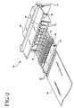
- Figure 2 is an exploded perspective view of the multi-pin connector for a flat flexible cable according to the present invention.
- Figure 3 is a perspective cross-sectional view of the multi-pin connector in the straight configuration according to the present invention.
- Figure 4 is a perspective cross-sectional view of the multi-pin connector in the right-angle configuration according to the present invention.
- Figure 5 is a perspective view of the straight configuration terminal according to the present invention.
- Figure 6 is a perspective view of the right-angle configuration terminal according to the present invention.
- Figure 7 is a perspective view of the slide member according to the present invention.
- Multi-pin connector 10 generally includes an elongate insulative housing 11, a plurality of conductive terminals 12 and an insulative slide member 13.
- the multi-pin connector may be in a straight line configuration as shown in Figures 2 and 3 or may be in a right-angle configuration as shown in Figure 4.
- the insulative housing 11 is made of a non-conducting insulative material and is generally rectangular in shape.
- the housing 11 has a tail side 14, and a header side 15.
- the connector 10 may be configured in the straight-line configuration, where the tail side 14 and the header side 15 are on opposite sides of the housing 11.
- the connector 10 may be configured in the right-angle configuration, where the tail side 14 is perpendicular to the header side 15. Extending almost along the entire length of the tail side 14 is a longitudinal slot 16.
- the width and depth of the slot 16 are sized to receive the slide member 13 and a flexible flat cable as discussed further below. Perpendicularly crossing the longitudinal slot 16 are a series of parallel slits 17.
- the slits 17 are sized to receive the terminals 12. Extending from the header side 15 of the housing 11 are a series of apertures 18 arranged generally in two parallel rows. Each aperture connects to a respective slit 17 and is sized to frictionally hold a pin portion of a terminal 12.
- the terminals 12 are preferably made from a thin electrically conductive metallic material. Each terminal includes a pin portion 19 and two contact arms 20 in a U-shaped configuration. Contact arms 20 are preferably J-shaped, the ends of which face inward. The terminals 12 must be made as to permit resilient outward deflection of the contact arms without damaging the terminals.
- the terminals for a straight-line connector are shaped such that the pin portion 19 extends in an opposite direction as the contact arms 20.
- the pin portion is off center with respect to the contact arms.
- the straight line connector requires only one shape for the terminals.
- the terminals 12 are inserted into the terminal slits 17 of the insulative housing 11 from the tail side 14 so that the pin portions 19 are frictionally held by the apertures 18 and protrude through the header side 15.
- the terminals 12 are installed in the terminal slits 17 of the housing 11 in a configuration in which every other terminal is axially rotated 180° with respect to the previous one, thereby defining two rows of laterally staggered pin portions protruding through the header side of the insulative housing as shown in Figures 2 and 3.
- the pin portion 19 of the terminal 12 extends perpendicularly to the contact arms 20 as shown in Figure 6.
- the terminals 20 are preferably provided in two shapes, the first shape having the pin portion extending perpendicularly from an upper location of one of the contact arms and the second shape having the pin portion extending perpendicularly from a lower location of a contact arm.
- the right-angle terminals are inserted in the housing in alternating shapes to form two rows of pin portions protruding through the header side of the housing as shown in Figure 4.
- the pin portions 19 are preferably offset from the plane of the contact arms 20 such that when installed in the housing the pin portions of two adjacent terminals form a vertical pair. In this manner, the pin portions protruding through the header side of the insulative housing will define a series of parallel vertical pairs.
- the slide member 13 is preferably made from the same insulative material as the housing 11.
- the slide member 13 is roughly the same length as the longitudinal slot 16 and is shaped to be laterally inserted within the slot along with a flat flexible cable.
- the slide member 13 preferably includes an upper surface 21 having an inclined portion 22 which is adapted to bias the flat cable into contact with the upper row of contact arms as discussed further below.
- Attached to the sides of the slide member 13 are flexible spring fingers 23 which are capable of slight inward deflection. Each spring finger 23 has a latch projection 24 which cooperatively engages a socket 25 of the insulative housing when the slide member is inserted within the longitudinal slot.
- a flat flexible cable 26 having exposed contact pads 27 is first inserted into the longitudinal slot 16 between the rows of contact arms 20 of the terminals 12.
- the slide member 13 is then inserted between the flat flexible cable 26 and the lower row of contact arms.
- the inclined portion 22 of the upper surface 21 gently presses the flat cable against the upper row of contact arms making electrical connection between the flat flexible cable and the terminals.
- the slide member 13 is inserted into the longitudinal slot 16 further until the latch projections 24 engage the sockets 25 of the housing.
- the spring latch and socket combination releasably retains the slide member within the longitudinal slot of the housing thereby maintaining the flat flexible cable within the connector and against the upper row of contact arms of the terminals.
- the multi-pin connector 10 is mounted to an external surface of an electrical device such that the header side 15 projects outwardly from the electrical device allowing for external electrical connection to the pin portions of the terminals.
- an internal flat flexible cable of an electrical device is connected to an external port of the device without the need for soldering.
- the flat flexible cable is quickly and easily connected to the multi-pin connector and may be easily disconnected by releasing the latch of the slide member from the socket of the housing and removing the slide member.
Landscapes
- Coupling Device And Connection With Printed Circuit (AREA)
Abstract
Description
- The present invention relates to electrical connectors for flat cables, and more particularly relates to a low insertion force (LIF) connector for providing an external electrical interface for an internal flat cable of an electrical device.
- Use of low insertion force (LIF) and zero insertion force (ZIF) connectors on printed circuit boards for receiving a flexible printed circuit (FPC) or a flexible flat cable (FFC) is well known in the field. LIF and ZIF relate to the technology of providing an electrical connector with the means in which conductors are inserted into the connector under relatively friction free and damage free conditions. Such connectors are typically soldered or otherwise affixed to an internal circuit board of an electrical device. An FPC or FFC is inserted into the connector and held in place to ensure positive electrical contact between the conductors of the FPC or FFC and the terminals of the connector. Various means of inserting and holding the FPC or FFC using low or zero insertion force are used to prevent damage to the FPC or FFC or damage to the components of the connector.
- For example, U.S. Patent No. 5,562,487 to Ii et al. discloses an electrical connector having an actuator which is slidably inserted in the connector housing. The actuator has a flat surface portion upon which a flat flexible cable may lie during friction free insertion of the actuator and cable into the housing. Thus inserted, the flexible flat cable makes electrical contact with the terminals of the connector. The terminals include solder tails which extend out of the connector housing which are soldered to a printed circuit board.
- Similarly, U.S. Patent No. 4,640,562 to Shoemaker discloses a surface mounting means for an electrical connector to a printed circuit board which includes a wedge plate for forcing contact of the flexible cable to the terminals of the connector. The connector is releasably mounted to the surface of the circuit board making electrical contact between the terminals and the conductors of the circuit board. These and other LIF and ZIF connectors provide efficient, damage free electrical connection between flexible flat cables or flexible printed circuits and internal circuit boards.
- Each of the above described connectors are designed to establish LIF or ZIF interconnection to internal components of an electrical device. However, the use of LIF or ZIF termination technology has not been shown in an external environment. Certain electrical devices, such as personal computers and disk drives, require an external interface for an internal component. A multi-pin connector is typically provided on such devices to connect a flexible flat cable to an external port of the device. Figure 1 shows a conventional external
multi-pin connector 100 for a flatflexible cable 101. Theconventional connector 100 is provided with box-pin terminals 102 havingsolder tails 103 which engage through holes of the flat flexible cable. Astrain relief bar 104 is also provided on the connector to hold the cable in place. Once the flatflexible cable 101 is linked to an internal component of the device, such as a printed circuit board or a hard disk actuating arm, the other end of the cable is connected to the external connector by through hole tin-lead soldering. This process tends to be costly and intricate as the soldering operation involves targeting the through holes of the flex cable to the solder tails after passing the cable through the connector's strain relief bar. - Accordingly, it is desirable to provide ZIF or LIF technology to an external connector for a flat flexible cable extending from an internal component which in turn would provide quick and easy connection and disconnection between the flat flexible cable and the external connector.
- It is an object of the present invention to provide a multi-pin external connector for a flat flexible cable which utilizes low insertion force technology.
- It is another object of the present invention to provide an external multi-pin connector for a flexible flat cable which eliminates the process of soldering the flat cable to the connector.
- It is yet another object of the present invention to provide an external multi-pin connector for a flat flexible cable in which the cable is quickly and easily connected and disconnected to the connector.
- In accordance with one form of the present invention a low insertion force multi-pin connector for a flat flexible cable generally includes an elongate insulative housing, a plurality of conductive terminals mounted in the housing and an insulative slide member. The insulative housing includes a tail side, a header side, a longitudinal slot disposed on the tail side, a plurality of slits disposed on the tail side and arranged perpendicularly across the longitudinal slot and a plurality of apertures extending from the header side which are in communication with respective slits. The conductive terminals each comprise a pin portion and two contact arms, each contact arm being capable of being outwardly deflected. The terminals are mounted within respective slits of the insulative housing such that the pin portions protrude through the apertures of the header side and the contact arms form generally parallel rows of upper and lower contact arms on the tail side. The insulative slide member is shaped to be inserted, along with the flat flexible cable, into the longitudinal slot of the tail side of the housing. In operation, the flat cable is first inserted into the longitudinal slot of the housing between the upper and lower contact arms. The slide member is then inserted into the longitudinal slot pressing the flat cable against either the upper or lower rows of contact arms thereby making electrical connection between the flat cable and the terminals. The connector is mounted to an external surface of an electrical device such that the header side of the housing projects outwardly to provide external electrical connection to the pin portions of the terminals.
- The multi-pin connector may be shaped to provide straight electrical connection or right-angle electrical connection. For straight electrical connection, the terminals are shaped such that the contact arms extend in an opposite direction as the pin portion and the header side and the tail side of the insulative housing are on opposite generally parallel surfaces. In a preferred embodiment of the straight configuration, the terminals are installed within the insulative housing in a configuration in which every other terminal is rotated 180° forming two rows of pin portions protruding through the header side of the insulative housing.
- In the right-angle configuration, the terminals are shaped such that the pin portion extends perpendicularly to the contact arms and the header side and tail side of the insulative housing are disposed on perpendicular surfaces. In a preferred embodiment of the right-angle configuration, the terminals are formed in one of two shapes, the first shape having the pin portion extending perpendicularly from a contact arm at an upper location and the second shape having the pin portion extending from the contact arm at a lower location. The terminals are then installed in the housing in alternating shapes forming two rows of pin portions protruding through the header side of the housing. In either the straight or right angle configuration, the pin portions of the terminal are preferably laterally offset from the plane of the contact arms. Preferably, the contact arms also include J-shaped end portions facing inwardly between the contact arms to provide better contact between the terminals and the flat cable.
- The slide member preferably includes an upper surface having an inclined portion adapted to bias the flat flexible cable into contact with one of the rows of contact arms when the flat cable and slide member are inserted in the longitudinal slot of the housing. The slide member and the insulative housing also preferably include a cooperating latch and socket mechanism for releasably retaining the slide member in the longitudinal slot of the insulative housing.
- These and other objects, features and advantages of the present invention will become apparent from the following detailed description of illustrative embodiments thereof, which is to be read in connection with the accompanying drawings.
- Figure 1 is a perspective view of a prior art multi-pin connector for a flat flexible cable.
- Figure 2 is an exploded perspective view of the multi-pin connector for a flat flexible cable according to the present invention.
- Figure 3 is a perspective cross-sectional view of the multi-pin connector in the straight configuration according to the present invention.
- Figure 4 is a perspective cross-sectional view of the multi-pin connector in the right-angle configuration according to the present invention.
- Figure 5 is a perspective view of the straight configuration terminal according to the present invention.
- Figure 6 is a perspective view of the right-angle configuration terminal according to the present invention.
- Figure 7 is a perspective view of the slide member according to the present invention.
- Referring now to Figures 2-7, a low insertion force multi-pin connector for a flat flexible cable formed in accordance with the present invention is shown.
Multi-pin connector 10 generally includes an elongateinsulative housing 11, a plurality ofconductive terminals 12 and aninsulative slide member 13. The multi-pin connector may be in a straight line configuration as shown in Figures 2 and 3 or may be in a right-angle configuration as shown in Figure 4. - The
insulative housing 11 is made of a non-conducting insulative material and is generally rectangular in shape. Thehousing 11 has atail side 14, and aheader side 15. As shown in Figures 2 and 3 theconnector 10 may be configured in the straight-line configuration, where thetail side 14 and theheader side 15 are on opposite sides of thehousing 11. As shown in Figure 4 theconnector 10 may be configured in the right-angle configuration, where thetail side 14 is perpendicular to theheader side 15. Extending almost along the entire length of thetail side 14 is alongitudinal slot 16. The width and depth of theslot 16 are sized to receive theslide member 13 and a flexible flat cable as discussed further below. Perpendicularly crossing thelongitudinal slot 16 are a series ofparallel slits 17. Theslits 17 are sized to receive theterminals 12. Extending from theheader side 15 of thehousing 11 are a series ofapertures 18 arranged generally in two parallel rows. Each aperture connects to arespective slit 17 and is sized to frictionally hold a pin portion of a terminal 12. - The
terminals 12 are preferably made from a thin electrically conductive metallic material. Each terminal includes apin portion 19 and twocontact arms 20 in a U-shaped configuration. Contactarms 20 are preferably J-shaped, the ends of which face inward. Theterminals 12 must be made as to permit resilient outward deflection of the contact arms without damaging the terminals. - Referring to Figure 5, the terminals for a straight-line connector are shaped such that the
pin portion 19 extends in an opposite direction as thecontact arms 20. Preferably, the pin portion is off center with respect to the contact arms. The straight line connector requires only one shape for the terminals. Theterminals 12 are inserted into the terminal slits 17 of theinsulative housing 11 from thetail side 14 so that thepin portions 19 are frictionally held by theapertures 18 and protrude through theheader side 15. Preferably, theterminals 12 are installed in the terminal slits 17 of thehousing 11 in a configuration in which every other terminal is axially rotated 180° with respect to the previous one, thereby defining two rows of laterally staggered pin portions protruding through the header side of the insulative housing as shown in Figures 2 and 3. - For a right-angle connector, the
pin portion 19 of the terminal 12 extends perpendicularly to thecontact arms 20 as shown in Figure 6. For a right-angle connector theterminals 20 are preferably provided in two shapes, the first shape having the pin portion extending perpendicularly from an upper location of one of the contact arms and the second shape having the pin portion extending perpendicularly from a lower location of a contact arm. The right-angle terminals are inserted in the housing in alternating shapes to form two rows of pin portions protruding through the header side of the housing as shown in Figure 4. In either the straight-line or right-angle configuration, thepin portions 19 are preferably offset from the plane of thecontact arms 20 such that when installed in the housing the pin portions of two adjacent terminals form a vertical pair. In this manner, the pin portions protruding through the header side of the insulative housing will define a series of parallel vertical pairs. - The
slide member 13 is preferably made from the same insulative material as thehousing 11. Theslide member 13 is roughly the same length as thelongitudinal slot 16 and is shaped to be laterally inserted within the slot along with a flat flexible cable. Theslide member 13 preferably includes anupper surface 21 having aninclined portion 22 which is adapted to bias the flat cable into contact with the upper row of contact arms as discussed further below. Attached to the sides of theslide member 13 areflexible spring fingers 23 which are capable of slight inward deflection. Eachspring finger 23 has alatch projection 24 which cooperatively engages asocket 25 of the insulative housing when the slide member is inserted within the longitudinal slot. - In use, a flat
flexible cable 26 having exposedcontact pads 27 is first inserted into thelongitudinal slot 16 between the rows ofcontact arms 20 of theterminals 12. Theslide member 13 is then inserted between the flatflexible cable 26 and the lower row of contact arms. As theslide member 13 is inserted theinclined portion 22 of theupper surface 21 gently presses the flat cable against the upper row of contact arms making electrical connection between the flat flexible cable and the terminals. Theslide member 13 is inserted into thelongitudinal slot 16 further until thelatch projections 24 engage thesockets 25 of the housing. The spring latch and socket combination releasably retains the slide member within the longitudinal slot of the housing thereby maintaining the flat flexible cable within the connector and against the upper row of contact arms of the terminals. Themulti-pin connector 10 is mounted to an external surface of an electrical device such that theheader side 15 projects outwardly from the electrical device allowing for external electrical connection to the pin portions of the terminals. - Thus, in accordance with the present invention an internal flat flexible cable of an electrical device is connected to an external port of the device without the need for soldering. The flat flexible cable is quickly and easily connected to the multi-pin connector and may be easily disconnected by releasing the latch of the slide member from the socket of the housing and removing the slide member.
- Although the illustrative embodiments of the present invention have been described herein with reference to the accompanying drawings, it is to be understood that the invention is not limited to those precise embodiments, and that various other changes and modifications may be effected therein by one skilled in the art without departing from the scope and spirit of the invention.
Claims (10)
- A multi-pin connector for providing an external electrical interface for an internal flat cable of an electrical device, the flat cable having exposed conductive portions along a single surface thereof, said connector comprising:an elongate insulative housing having a tail side, a header side and a longitudinal slot disposed on said tail side;a plurality of conductive terminals each comprising a pin portion and two contact arms in a U-shaped configuration so as to define a pair of generally parallel legs each being capable of being deflectable outwardly, each terminal being mounted within the insulative housing forming generally parallel rows of upper and lower contact arts on said tail side with said pin portions protruding through said header side; andan insulative slide member shaped to be laterally inserted within said longitudinal slot along with the flat cable,wherein the flat cable is inserted in said longitudinal slot between said upper and lower rows of contact arms and said slide member is inserted in said longitudinal slot between the flat cable and one of said rows and elastically presses the exposed conductive portions of the single surface of the flat cable against the other of said rows making internal electrical connection between the conductive portions and said terminals and wherein said connector is mounted to the electrical device such that said header side projects outwardly from an external surface of the electrical device to provide external electrical connection to said pin portions;wherein said slide member includes a deflectable spring latch integrally formed therewith and said housing includes a latch receiving socket for releasably engaging said latch for releasably retaining said slide member within said housing, said release of said latch from said socket providing for disconnection of said flat cable from said terminals.
- The multi-pin connector as defined in Claim 1 wherein the insulative housing further comprises a plurality of slits and apertures, said slits being disposed on the tail side and arranged perpendicularly across the slot and said apertures extending from the header side, each aperture in communication with a respective slit, and wherein the conductive terminals are mounted within said respective slits of the insulative housing forming generally parallel rows of upper and lower contact arms on the tail side with the pin portions protruding through said apertures of the header side.
- The multi-pin connector as defined in Claim 1 wherein each terminal is shaped such that the contact arms extend in an opposite direction as the pin portion and wherein the header side and the tail side of the insulative housing are generally parallel with respect to each other forming a straight electrical connection between said header side and said tail side.
- The multi-pin connector as defined in Claim 3 wherein the terminals are installed within the insulative housing in a configuration in which every other terminal is axially rotated 180°, with respect to the previous one, which defines two rows of pin portions protruding through the header side of the insulative housing.
- The multi-pin connector as defined in Claim 4 wherein the pin portion of each terminal is laterally offset from the plane of the contact arms.
- The multi-pin connector as defined in Claim 1 wherein each terminal is shaped such that the pin portion extends perpendicularly to the contact arms and wherein the header side and the tail side of the insulative housing are generally perpendicular with respect to each other forming a right-angle electrical connection between said header side and said tail side.
- The multi-pin connector as defined in Claim 11 wherein each terminal is shaped in one of two configurations, the first configuration having the pin portion extending perpendicularly from the contact arms at an upper location and the second configuration having the pin portion extending from the contact arms at a lower location and wherein said terminals are installed within the insulative housing in alternating configurations, which defines two rows of pin portions protruding through the header side of the insulative housing.
- The multi-pin connector as defined in Claim 7 wherein the pin portion of each terminal is laterally offset from the plane of the contact arms.
- The multi-pin connector as defined in Claim 1 wherein the contact arms of each terminal include J-shaped portions at the ends thereof, the ends of said J-shaped portions facing inwardly between the contact arms.
- The multi-pin connector as defined in claim 11 wherein the slide member includes an upper surface having an inclined surface portion adapted to bias the flat cable into contact with one of the rows of contact arms when the flat cable and slide member are inserted in the longitudinal slot of the insulative housing.
Applications Claiming Priority (2)
| Application Number | Priority Date | Filing Date | Title |
|---|---|---|---|
| US86830 | 1998-05-29 | ||
| US09/086,830 US5928029A (en) | 1998-05-29 | 1998-05-29 | Multi-pin connector for flat cable |
Publications (2)
| Publication Number | Publication Date |
|---|---|
| EP0961352A1 true EP0961352A1 (en) | 1999-12-01 |
| EP0961352B1 EP0961352B1 (en) | 2008-05-14 |
Family
ID=22201198
Family Applications (1)
| Application Number | Title | Priority Date | Filing Date |
|---|---|---|---|
| EP99201673A Expired - Lifetime EP0961352B1 (en) | 1998-05-29 | 1999-05-27 | Multi-pin connector for flat cable |
Country Status (6)
| Country | Link |
|---|---|
| US (1) | US5928029A (en) |
| EP (1) | EP0961352B1 (en) |
| JP (1) | JP2000030779A (en) |
| CA (1) | CA2273114A1 (en) |
| DE (1) | DE69938692D1 (en) |
| SG (1) | SG75962A1 (en) |
Families Citing this family (26)
| Publication number | Priority date | Publication date | Assignee | Title |
|---|---|---|---|---|
| US6244890B1 (en) * | 1998-03-27 | 2001-06-12 | Molex Incorporated | Male electrical connector for flat flexible circuit |
| JP2000252598A (en) * | 1999-03-02 | 2000-09-14 | Fuji Photo Film Co Ltd | Flexible printed-wiring board |
| US6089904A (en) * | 1999-04-16 | 2000-07-18 | Hon Hai Precision Ind. Co., Ltd. | FFC connector |
| TW433638U (en) * | 1999-10-01 | 2001-05-01 | Hon Hai Prec Ind Co Ltd | Electrical connector |
| JP2001176586A (en) * | 1999-12-21 | 2001-06-29 | Citizen Electronics Co Ltd | Sounding element with connector |
| GB0104736D0 (en) * | 2001-02-26 | 2001-04-18 | Varintelligent Bvi Ltd | Electrical cable |
| US6854995B2 (en) * | 2001-11-07 | 2005-02-15 | Tyco Electronics Amp Gmbh | Connector for detachably connecting an electrically conductive foil to a contact |
| TW534493U (en) * | 2002-06-20 | 2003-05-21 | Hon Hai Prec Ind Co Ltd | Electrical connector |
| US7044773B2 (en) * | 2002-08-01 | 2006-05-16 | Ddk Ltd. | Connector |
| US6869308B2 (en) * | 2002-12-11 | 2005-03-22 | Hon Hai Precision Ind. Co., Ltd. | Cable connector having cross-talk suppressing feature and method for making the connector |
| JP4145226B2 (en) * | 2002-12-26 | 2008-09-03 | 第一電子工業株式会社 | connector |
| CN1993867B (en) * | 2004-08-10 | 2011-04-27 | 第一电子工业株式会社 | Connector |
| JP4578931B2 (en) * | 2004-10-18 | 2010-11-10 | 第一電子工業株式会社 | connector |
| US7625240B2 (en) * | 2007-10-26 | 2009-12-01 | Cisco Technology, Inc. | Receptacle connector |
| US20110159710A1 (en) * | 2009-12-31 | 2011-06-30 | Crighton Alan D | Array of electrical connectors having offset electrical connectors |
| JP2011146223A (en) * | 2010-01-14 | 2011-07-28 | Yazaki Corp | Flat circuit body |
| BRPI1104453A2 (en) * | 2010-09-07 | 2015-12-22 | Framatome Connectors Int | electrical connector arrangement and method for transmitting data from one module |
| US8535089B2 (en) | 2011-07-25 | 2013-09-17 | Tyco Electronics Corporation | Connector assembly |
| US8430685B2 (en) * | 2011-07-25 | 2013-04-30 | Tyco Electronics Corporation | Connector assembly |
| JP6074711B2 (en) * | 2013-09-10 | 2017-02-08 | パナソニックIpマネジメント株式会社 | Cable holding member, electrical connection device, connector device |
| US9373903B2 (en) * | 2014-01-28 | 2016-06-21 | Wei Sun Chang | Flexible flat cable connector and flexible flat cable thereof |
| USD722980S1 (en) | 2014-04-25 | 2015-02-24 | Xerox Corporation | Latch apparatus for retaining a flexible circuit cable within a receptacle mounted on a circuit board |
| US9184522B1 (en) | 2014-04-25 | 2015-11-10 | Xerox Corporation | Latch apparatus for retaining a flexible circuit cable within a receptacle mounted on a circuit board |
| DE102015211027B4 (en) * | 2015-06-16 | 2025-03-20 | Zf Friedrichshafen Ag | Chip protection for printed circuit boards |
| US10211552B2 (en) * | 2016-10-21 | 2019-02-19 | Foxconn Interconnect Technology Limited | Cable connector assembly having space-saving connection between cable wire conductors and contact terminating portions |
| CN113764947B (en) * | 2020-06-02 | 2025-10-14 | 山一电机株式会社 | Socket, IC package and method for mounting contact piece to connector housing |
Citations (4)
| Publication number | Priority date | Publication date | Assignee | Title |
|---|---|---|---|---|
| US4624515A (en) * | 1985-04-17 | 1986-11-25 | Thomas & Betts Corporation | Electrical connector with grounding clip |
| EP0419818A1 (en) * | 1989-09-25 | 1991-04-03 | Robinson Nugent, Inc. | Edge card connector having preloaded contacts |
| US5308262A (en) * | 1991-12-10 | 1994-05-03 | Sumitomo Wiring Systems, Ltd. | Electric connector for flexible ribbon cable |
| US5507650A (en) * | 1992-11-16 | 1996-04-16 | Hjs & E Engineering | Universal slide mounted adaptor for storage devices |
Family Cites Families (19)
| Publication number | Priority date | Publication date | Assignee | Title |
|---|---|---|---|---|
| US4367006A (en) * | 1980-12-10 | 1983-01-04 | Amp Incorporated | Connector for flat cable |
| US4449773A (en) * | 1982-05-07 | 1984-05-22 | Amp Incorporated | Low insertion force connector |
| US4477137A (en) * | 1982-08-23 | 1984-10-16 | Allied Corporation | Zero insertion force connector for flat cable |
| US4592611A (en) * | 1984-09-27 | 1986-06-03 | Amp Incorporated | Electrical connector intended for use in confined areas |
| US4640562A (en) * | 1984-12-19 | 1987-02-03 | Amp Incorporated | Surface mounting means for printed circuit board |
| GB8810581D0 (en) * | 1988-05-05 | 1988-06-08 | Amp Holland | Zero insertion force connector for wire to board applications |
| US4850899A (en) * | 1988-06-20 | 1989-07-25 | Maynard Scott D | Connector for interfacing a disk drive with a computer |
| US4863395A (en) * | 1989-01-17 | 1989-09-05 | Robert Babuka | Zero insertion force connector with component card |
| FR2654557B1 (en) * | 1989-11-10 | 1992-01-17 | Labinal | MALE ELECTRIC CONTACT MEMBER AND CORRESPONDING ELECTRICAL CONNECTION BOX. |
| US5100342A (en) * | 1990-03-30 | 1992-03-31 | Amp Incorporated | High density flat cable connector |
| US5240430A (en) * | 1991-10-31 | 1993-08-31 | Amp Incorporated | Electrical connector for cable to circit board application |
| US5213534A (en) * | 1992-07-31 | 1993-05-25 | Molex Incorporated | Electrical connector assembly for flat flexible cable |
| US5474468A (en) * | 1992-09-14 | 1995-12-12 | Sumitomo Wiring Systems, Ltd. | Connector |
| US5370552A (en) * | 1992-09-16 | 1994-12-06 | Sumitomo Wiring Systems, Ltd. | Electrical connector |
| JP2575272Y2 (en) * | 1993-01-27 | 1998-06-25 | 日本エー・エム・ピー株式会社 | Flat cable connector |
| US5354214A (en) * | 1993-07-23 | 1994-10-11 | Molex Incorporated | Printed circuit board electrical connector with mounting latch clip |
| JP2593430Y2 (en) * | 1993-09-09 | 1999-04-12 | エスエムケイ株式会社 | FPC / FFC connector |
| JPH07230860A (en) * | 1994-02-09 | 1995-08-29 | Molex Inc | Electric connector |
| JP3368661B2 (en) * | 1994-03-04 | 2003-01-20 | 住友電装株式会社 | Flat cable connector fitting jig |
-
1998
- 1998-05-29 US US09/086,830 patent/US5928029A/en not_active Expired - Fee Related
-
1999
- 1999-05-26 CA CA002273114A patent/CA2273114A1/en not_active Abandoned
- 1999-05-27 DE DE69938692T patent/DE69938692D1/en not_active Expired - Fee Related
- 1999-05-27 SG SG1999002733A patent/SG75962A1/en unknown
- 1999-05-27 EP EP99201673A patent/EP0961352B1/en not_active Expired - Lifetime
- 1999-05-28 JP JP11149490A patent/JP2000030779A/en active Pending
Patent Citations (4)
| Publication number | Priority date | Publication date | Assignee | Title |
|---|---|---|---|---|
| US4624515A (en) * | 1985-04-17 | 1986-11-25 | Thomas & Betts Corporation | Electrical connector with grounding clip |
| EP0419818A1 (en) * | 1989-09-25 | 1991-04-03 | Robinson Nugent, Inc. | Edge card connector having preloaded contacts |
| US5308262A (en) * | 1991-12-10 | 1994-05-03 | Sumitomo Wiring Systems, Ltd. | Electric connector for flexible ribbon cable |
| US5507650A (en) * | 1992-11-16 | 1996-04-16 | Hjs & E Engineering | Universal slide mounted adaptor for storage devices |
Also Published As
| Publication number | Publication date |
|---|---|
| SG75962A1 (en) | 2000-10-24 |
| US5928029A (en) | 1999-07-27 |
| DE69938692D1 (en) | 2008-06-26 |
| CA2273114A1 (en) | 1999-11-29 |
| JP2000030779A (en) | 2000-01-28 |
| EP0961352B1 (en) | 2008-05-14 |
Similar Documents
| Publication | Publication Date | Title |
|---|---|---|
| US5928029A (en) | Multi-pin connector for flat cable | |
| CN101133522B (en) | Board Mount Electrical Connectors | |
| US5127839A (en) | Electrical connector having reliable terminals | |
| US4867690A (en) | Electrical connector system | |
| US6162083A (en) | Electrical connector system for flat circuitry | |
| US4891019A (en) | Electrical connector for interconnecting a printed circuit board to a ribbon cable | |
| US5415573A (en) | Edge mounted circuit board electrical connector | |
| CN100420100C (en) | Board mountable connector combinations | |
| EP0630080A2 (en) | Circuit board mounted modular phone jack | |
| JPH02295077A (en) | Surface mounting electric connector | |
| US6733305B2 (en) | Board-to-board electrical connector assembly | |
| US5292265A (en) | Edge mounted circuit board electrical connector | |
| US6089883A (en) | Board-to-board connector assembly | |
| EP0632549B1 (en) | Electrical connector assembly | |
| EP0397075A2 (en) | Printed circuit board edge connector | |
| EP0856922B1 (en) | Board straddle mounted electrical connector | |
| EP0708502B1 (en) | An assembly of an electrical connector and a flexible printed circuit board with an insulating resilient piece | |
| US6692273B1 (en) | Straddle mount connector | |
| EP0191539A2 (en) | Electrical connecting terminal for a connector | |
| US5167544A (en) | Female electrical contact | |
| KR970068043A (en) | Small pitch electrical connectors | |
| EP0204475A2 (en) | Electrical connector with switch | |
| US4679890A (en) | Connector contact terminal | |
| US5980296A (en) | Connecting structure for flat circuit body and connector | |
| JP3898643B2 (en) | Small board to board connector |
Legal Events
| Date | Code | Title | Description |
|---|---|---|---|
| PUAI | Public reference made under article 153(3) epc to a published international application that has entered the european phase |
Free format text: ORIGINAL CODE: 0009012 |
|
| AK | Designated contracting states |
Kind code of ref document: A1 Designated state(s): BE CH DE ES FR GB IT LI LU NL SE |
|
| AX | Request for extension of the european patent |
Free format text: AL;LT;LV;MK;RO;SI |
|
| 17P | Request for examination filed |
Effective date: 20000127 |
|
| AKX | Designation fees paid |
Free format text: BE CH DE ES FR GB IT LI LU NL SE |
|
| RAP1 | Party data changed (applicant data changed or rights of an application transferred) |
Owner name: THOMAS & BETTS INTERNATIONAL, INC. |
|
| GRAP | Despatch of communication of intention to grant a patent |
Free format text: ORIGINAL CODE: EPIDOSNIGR1 |
|
| RIC1 | Information provided on ipc code assigned before grant |
Ipc: H01R 12/16 20060101ALI20071116BHEP Ipc: H01R 12/24 20060101ALI20071116BHEP Ipc: H01R 12/38 20060101ALI20071116BHEP Ipc: H01R 12/08 20060101AFI20071116BHEP |
|
| GRAS | Grant fee paid |
Free format text: ORIGINAL CODE: EPIDOSNIGR3 |
|
| GRAA | (expected) grant |
Free format text: ORIGINAL CODE: 0009210 |
|
| AK | Designated contracting states |
Kind code of ref document: B1 Designated state(s): BE CH DE ES FR GB IT LI LU NL SE |
|
| REG | Reference to a national code |
Ref country code: GB Ref legal event code: FG4D |
|
| REG | Reference to a national code |
Ref country code: CH Ref legal event code: EP |
|
| REF | Corresponds to: |
Ref document number: 69938692 Country of ref document: DE Date of ref document: 20080626 Kind code of ref document: P |
|
| PG25 | Lapsed in a contracting state [announced via postgrant information from national office to epo] |
Ref country code: ES Free format text: LAPSE BECAUSE OF FAILURE TO SUBMIT A TRANSLATION OF THE DESCRIPTION OR TO PAY THE FEE WITHIN THE PRESCRIBED TIME-LIMIT Effective date: 20080825 |
|
| NLV1 | Nl: lapsed or annulled due to failure to fulfill the requirements of art. 29p and 29m of the patents act | ||
| PG25 | Lapsed in a contracting state [announced via postgrant information from national office to epo] |
Ref country code: NL Free format text: LAPSE BECAUSE OF FAILURE TO SUBMIT A TRANSLATION OF THE DESCRIPTION OR TO PAY THE FEE WITHIN THE PRESCRIBED TIME-LIMIT Effective date: 20080514 |
|
| REG | Reference to a national code |
Ref country code: CH Ref legal event code: PL |
|
| PG25 | Lapsed in a contracting state [announced via postgrant information from national office to epo] |
Ref country code: SE Free format text: LAPSE BECAUSE OF FAILURE TO SUBMIT A TRANSLATION OF THE DESCRIPTION OR TO PAY THE FEE WITHIN THE PRESCRIBED TIME-LIMIT Effective date: 20080814 Ref country code: LI Free format text: LAPSE BECAUSE OF NON-PAYMENT OF DUE FEES Effective date: 20080531 Ref country code: CH Free format text: LAPSE BECAUSE OF NON-PAYMENT OF DUE FEES Effective date: 20080531 |
|
| PG25 | Lapsed in a contracting state [announced via postgrant information from national office to epo] |
Ref country code: BE Free format text: LAPSE BECAUSE OF FAILURE TO SUBMIT A TRANSLATION OF THE DESCRIPTION OR TO PAY THE FEE WITHIN THE PRESCRIBED TIME-LIMIT Effective date: 20080514 |
|
| PLBE | No opposition filed within time limit |
Free format text: ORIGINAL CODE: 0009261 |
|
| STAA | Information on the status of an ep patent application or granted ep patent |
Free format text: STATUS: NO OPPOSITION FILED WITHIN TIME LIMIT |
|
| 26N | No opposition filed |
Effective date: 20090217 |
|
| PG25 | Lapsed in a contracting state [announced via postgrant information from national office to epo] |
Ref country code: IT Free format text: LAPSE BECAUSE OF FAILURE TO SUBMIT A TRANSLATION OF THE DESCRIPTION OR TO PAY THE FEE WITHIN THE PRESCRIBED TIME-LIMIT Effective date: 20080514 |
|
| PGFP | Annual fee paid to national office [announced via postgrant information from national office to epo] |
Ref country code: FR Payment date: 20090518 Year of fee payment: 11 Ref country code: DE Payment date: 20090528 Year of fee payment: 11 |
|
| PGFP | Annual fee paid to national office [announced via postgrant information from national office to epo] |
Ref country code: GB Payment date: 20090528 Year of fee payment: 11 |
|
| PG25 | Lapsed in a contracting state [announced via postgrant information from national office to epo] |
Ref country code: LU Free format text: LAPSE BECAUSE OF NON-PAYMENT OF DUE FEES Effective date: 20080527 |
|
| GBPC | Gb: european patent ceased through non-payment of renewal fee |
Effective date: 20100527 |
|
| REG | Reference to a national code |
Ref country code: FR Ref legal event code: ST Effective date: 20110131 |
|
| PG25 | Lapsed in a contracting state [announced via postgrant information from national office to epo] |
Ref country code: DE Free format text: LAPSE BECAUSE OF NON-PAYMENT OF DUE FEES Effective date: 20101201 |
|
| PG25 | Lapsed in a contracting state [announced via postgrant information from national office to epo] |
Ref country code: FR Free format text: LAPSE BECAUSE OF NON-PAYMENT OF DUE FEES Effective date: 20100531 |
|
| PG25 | Lapsed in a contracting state [announced via postgrant information from national office to epo] |
Ref country code: GB Free format text: LAPSE BECAUSE OF NON-PAYMENT OF DUE FEES Effective date: 20100527 |