EP0961127B1 - Adjustable fast press with PCB shuttle and modular expansion capabilities - Google Patents
Adjustable fast press with PCB shuttle and modular expansion capabilities Download PDFInfo
- Publication number
- EP0961127B1 EP0961127B1 EP98123646A EP98123646A EP0961127B1 EP 0961127 B1 EP0961127 B1 EP 0961127B1 EP 98123646 A EP98123646 A EP 98123646A EP 98123646 A EP98123646 A EP 98123646A EP 0961127 B1 EP0961127 B1 EP 0961127B1
- Authority
- EP
- European Patent Office
- Prior art keywords
- drawer
- press
- assembly
- plate
- testing
- Prior art date
- Legal status (The legal status is an assumption and is not a legal conclusion. Google has not performed a legal analysis and makes no representation as to the accuracy of the status listed.)
- Expired - Lifetime
Links
- 238000012360 testing method Methods 0.000 claims description 36
- 239000000523 sample Substances 0.000 claims description 31
- 230000001360 synchronised effect Effects 0.000 claims description 8
- 238000000034 method Methods 0.000 claims description 2
- 238000010998 test method Methods 0.000 claims description 2
- 230000007246 mechanism Effects 0.000 description 8
- 230000000712 assembly Effects 0.000 description 6
- 238000000429 assembly Methods 0.000 description 6
- 150000003071 polychlorinated biphenyls Chemical class 0.000 description 3
- 239000003381 stabilizer Substances 0.000 description 3
- 238000013459 approach Methods 0.000 description 2
- 230000005540 biological transmission Effects 0.000 description 2
- 239000000356 contaminant Substances 0.000 description 2
- 238000013023 gasketing Methods 0.000 description 2
- 238000009434 installation Methods 0.000 description 2
- 230000002093 peripheral effect Effects 0.000 description 2
- 238000004140 cleaning Methods 0.000 description 1
- 238000010276 construction Methods 0.000 description 1
- 238000013461 design Methods 0.000 description 1
- 230000009977 dual effect Effects 0.000 description 1
- 230000000694 effects Effects 0.000 description 1
- 238000003780 insertion Methods 0.000 description 1
- 230000037431 insertion Effects 0.000 description 1
- 238000012423 maintenance Methods 0.000 description 1
- 239000000463 material Substances 0.000 description 1
- 238000012986 modification Methods 0.000 description 1
- 230000004048 modification Effects 0.000 description 1
- 230000000737 periodic effect Effects 0.000 description 1
- 238000003825 pressing Methods 0.000 description 1
- 239000000126 substance Substances 0.000 description 1
- 238000013519 translation Methods 0.000 description 1
Images



Classifications
-
- G—PHYSICS
- G01—MEASURING; TESTING
- G01R—MEASURING ELECTRIC VARIABLES; MEASURING MAGNETIC VARIABLES
- G01R31/00—Arrangements for testing electric properties; Arrangements for locating electric faults; Arrangements for electrical testing characterised by what is being tested not provided for elsewhere
- G01R31/28—Testing of electronic circuits, e.g. by signal tracer
- G01R31/2851—Testing of integrated circuits [IC]
- G01R31/2886—Features relating to contacting the IC under test, e.g. probe heads; chucks
- G01R31/2887—Features relating to contacting the IC under test, e.g. probe heads; chucks involving moving the probe head or the IC under test; docking stations
Definitions
- the present invention relates generally to testing of printed circuit boards for use in electronic products and, specifically, to a press for engaging a printed circuit board to a probe card assembly.
- testers utilize a "bed-of-nails" design, which includes a probe surface having plural (thousands) of sockets that are interconnected to test equipment, such as a computer with the appropriate software.
- Test probes are insertable in these sockets and protrude upwardly from the probe surface. These probes are configured to match the input/output connection points of the electronic components, such as integrated circuits, resident on the printed circuit board (PCB) being tested. Further, the probes are biased upwardly such that, to ensure proper alignment, a card must be placed over the probes and sufficient downward force must be provided to the PCB such that proper electrical connection is made between the inputs/outputs of the electronic components and the test equipment, via the biased test probes.
- PCB printed circuit board
- Fixturing systems have been developed for purposes of handling printed circuit boards for testing.
- the most common of such fixturing systems is a vacuum fixture.
- vacuum fixturing atmospheric pressure acts directly on a PCB with a vacuum beneath it, forcing the board against spring loaded testing probes. Problems arise from the need to maintain a seal around and across the board. Maintaining a vacuum seal in an automated environment is even more troublesome.
- Warped printed circuit boards are commonly encountered and require a separate effort or effect to push and seat them in the fixture gasketing material. PCBs with holes or apertures generally complicate vacuum fixturing techniques because of the difficulty associated with maintaining a proper seal.
- probe density is limited by atmospheric pressure.
- vacuum fixtures generally do not provide sufficiently forceful contact between the probes and PCBs to displace contaminants present on the board surfaces, thereby necessitating additional costs and chemical disposal issues associated with pre-cleaning the boards before testing.
- the typical pneumatic fixturing system incorporates a flat plate attached to a cylinder. Pneumatic pressure is applied to the cylinder which in turn forces the plate against the printed circuit board disposed on the probes. Testing problems arise from the fact that the center of the plate receives the majority of the force applied by the cylinder. Accordingly, the periphery of the board may not sufficiently contact and be tested by the probes. This is especially true with large and/or thin PCBs. Further, such pneumatic systems are not height adjustable relative the probes and thus are unable to accommodate boards of varying thicknesses and/or component heights.
- a printed circuit board testing system that enables rapid and evenly distributed pressing of the boards to the test probes, allows adjustability of the press height so as to accommodate differently sized boards, and is modifiable to multiple configurations so as to enable multiple modes of operation.
- the invention relates to an apparatus for testing printed circuit boards as defined in claims 1 and 8, and to a method of testing as defined in claim 9.
- a mechanical press enabling quick and accurate testing of printed circuit board top and bottom sides in conjunction with a conventional probe card testing assembly.
- the press provides a fixed-stroke actuator coupled with a moveable frame, thereby permitting adjustment of the press relative to the workpiece.
- the press comprises plural actuators operating in unison to provide even distribution of force over the PCB.
- a mechanical press incorporating a stationary frame attached to the probe card testing assembly top plate.
- Four elongated rotatable lead screws protrude through the upper surface of the stationary frame in order to moveably support a press assembly, thereby permitting height adjustment.
- Each of the lead screws has a timing belt pulley or similar means for synchronous power transmission disposed above the stationary frame upper surface for driving the lead screw.
- a timing belt or similar continuous belt or chain engages each belt pulley, thereby synchronizing the rotation of the lead screws.
- the timing belt is further engaged with the teeth of a bi-directionally rotatable drive shaft proximal the stationary frame.
- the drive shaft and, accordingly, the lead screws are bi-directionally rotated in unison by an electrically-powered programmable motor thereby permitting the press assembly to be moved upwards or downwards.
- the press assembly which is suspended by the lead screws comprises a movable frame, a plate attached to the movable frame, and an actuator attached to the plate.
- the press assembly has four synchronized force-applying members that, when actuated, cause the plate to move rapidly downward a distance of 10 centimetres (approximately four inches).
- a shuttle system comprising a drawer and a pair of rails may optionally be provided to allow automatic and convenient circuit board insertion into and removal from the testing assembly.
- the drawer has a partially open bottom surface and is sized to accommodate a printed circuit board placed therein.
- the rails are attached to the stationary frame and are configured to engage the drawer and permit horizontal movement of the drawer along at least a portion of their length.
- a PCB press 10 includes a stationary frame 20 having flanges 50, which are attached to a conventional probe card testing assembly 30.
- Probe card testing assembly 30 includes a conventional probe card 40 used for testing a printed circuit board 160.
- PCB press 10 comprises press assembly 100, which is a fast-acting press that moves press plate 150 rapidly through a fixed stroke.
- Press assembly 100 is height adjustable within frame 20 by means of lead screw assemblies 70A 70B, 70C, and 70D disposed substantially proximal the peripheral corners of press assembly 100.
- lead screw assemblies 70A are described in detail, however, lead screw assemblies 70B-70D comprise substantially identical elements.
- Lead screw assembly 70A comprises an upper bearing portion 86A that rotates within but is constrained in the axial direction by bearing journal 88A disposed in press mount 60 of frame 20.
- Lower portion 90A of lead screw assembly 70A is threaded into a threaded boss 92A in press assembly upper plate 110 such that, when lead screw 70A is rotated, upper plate 110 (and with it press assembly 100) are drawn toward or forced away from press mount 60 of frame 20.
- a driving member 80A Disposed atop lead screw assembly 70 is a driving member 80A, which preferably comprises a gear, chain sprocket, timing belt pulley or similar apparatus for receiving synchronized power transmission.
- lead screw assemblies 70A-70D are disposed proximal the peripheral corners 72,73,74 75 of press assembly upper plate 110 (shown in dashed lines in FIG. 2).
- a conventional link-and-roller chain 170 engages driving members 80A-80D in conventional fashion to cause the rotation of all of lead screw assemblies 70A-70D to be synchronized.
- upper plate 110 can be moved toward or away from press mount 60 of frame 20 while maintaining upper plate 110 in a precisely horizontal attitude.
- stabilizer rail 211 is rigidly mounted in press mount 60 so as to slidingly engage a stabilizer bushing 212 in press assembly upper plate 110. Additional stabilizer rails may be added as required for the particular application.
- Lead screw assemblies 70A-70D may be manually adjusted or, as shown in FIG. 2, a drive motor 190 may be coupled via sprocket 210 to chain 170 thereby providing a power-adjustment feature.
- a conventional link-and-roller chain is disclosed in the illustrative embodiment, a timing belt, gear train, flexible shafting, or any other conventional means of synchronously driving a plurality of parallel shafts is contemplated within the present invention.
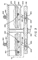
- FIG. 3 is a partial cross-section of FIG. 1 along line 3-3 with the press plate 150 near the fully extended position (press plate 150 is shown fully retracted in FIG. 1).
- press assembly 100 comprises side plates 101A and 101B, which are rigidly attached to opposite sides of press assembly upper plate 110.
- Each of side plates 101A and 101B support substantially equivalent actuator mechanisms 120A (FIG. 3) and 120B (not shown). Accordingly, for the sake of brevity, only the actuator mechanism supported by side plate 101A is discussed in detail herein.
- Side plate 101A has a channel 102A formed therein. Disposed within channel 102A is a linear gear, also known as a rack, 104A.
- Rack 104A engages driven pinions 106A and 108A and also engages a drive pinion 112A.
- Driven pinions 106A and 108A are coupled to bell crank arms 116A and 118A, respectively.
- Crank pins 122A and 124A, respectively, are disposed transversely in bell crank arms 116A and 118A, respectively, such that the distance from the center of pinion 106A to crank pin 122A is equal to the distance from the center of pinion 108A to crank pin 124A.
- Crank pin 122A engages a corresponding slot 132A in press plate 150 and crank pin 124A engages a corresponding slot 134A in press plate 150.
- rotary actuator 114 rotates drive pinion 112A, which in turn causes rack 104A to translate along channel 102A.
- Translation of rack 104A causes pinions 106A and 108A to rotate in unison, which causes bell crank arms 116A and 118A also to rotate in unison, thereby extending press plate 150 downward.
- Guide rail 300 is rigidly mounted to press assembly upper plate 110 such that it engages a guide bushing 310 in press plate 150.
- Guide rail 300 thereby constrains press plate 150 to move vertically along guide 300 as bell crank arms 116A and 118A rotate. Because bell crank arms 116A and 118A move in unison, press plate 150 is extended downward with equal downward pressure at both ends.
- the vertical force exerted by bell crank arms 116A and 118A is a function of 1/sin of the angle between bell crank arms 116A and 118A and the horizontal. Since 1/sin approaches infinity as the angle approaches 90 degrees, the vertical force multiplication exerted by bell crank arms 116A and 118A is highest at the beginning and end of the stroke. Thus, the actuator mechanism 120A moves rapidly through most of the stroke yet is able to exert a substantial downward force on the PCB being tested with a modest torque exerted at pinions 106A and 108A. In the illustrative embodiment, the distance between the center of pinions 106A and 108A is two inches. Thus, the total stroke of press plate 150 with bell crank arms 116A and 118A moving through 180 degrees is four inches.
- FIG. 4 is an isometric perspective view of press assembly 100.
- side plate 101B supports an actuator mechanism 120B, which is a functionally identical, mirror image of actuator mechanism 120A discussed herein.
- rotary actuator 114 comprises a conventional double-ended actuator having a common shaft 115 that drives both driven pinion 112A of actuator mechanism 120A and a corresponding driven pinion 112B of actuator mechanism 120B.
- rack 104A and rack 104B are translated synchronously within corresponding channels 102A and 102B. This in turn ensures that actuator mechanism 120A and 120B are synchronized and, therefore, that equal pressure is applied to all four corners of press plate 150.
- Rotary actuator 114 may be electrically or vacuum operated, but is preferably a conventional pneumatic rotary actuator.
- Brackets 125A and 125B depend from side plates 101A and 101B and provide an installation platform for optional conventional equipment that may be used to test electronic elements disposed on the upper surface of a PCB.
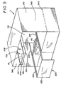
- PCB press 11 is shown with press assembly 100 disposed within stationary frame 210 which comprises a dual-bay version of frame 20. Also shown is an optional shuttle system 220 enabling mechanical placement of circuit board 160 upon testing assembly 30.
- Shuttle system 220 consists of at least one drawer 230 and a drawer support that may take the form of a set of rails 240, 241 and 242. Rails 240, 241 and 242 allow drawer 230 to move in and out of frame 20 and to be placed in a position below press assembly 100 for circuit board 160 testing. Movement of drawer 230 in an out of frame 20 may be manually or automatically produced.
- Drawer 230 has a substantially open bottom surface 250 that simultaneously supports a circuit board 160 placed thereon and enables interfacing forced by press plate 150 between circuit board 160 and probe card 40.
- Shuttle system 220 protects the fragile probe card assembly by providing a bed into which the operator places the PCB remote from the probe card assembly and thus enables precise regulation of the extent to which the PCB contacts the probe card assembly.
Landscapes
- Engineering & Computer Science (AREA)
- Computer Hardware Design (AREA)
- Microelectronics & Electronic Packaging (AREA)
- General Engineering & Computer Science (AREA)
- Physics & Mathematics (AREA)
- General Physics & Mathematics (AREA)
- Testing Or Measuring Of Semiconductors Or The Like (AREA)
- Tests Of Electronic Circuits (AREA)
- Testing Of Individual Semiconductor Devices (AREA)
- Measuring Leads Or Probes (AREA)
Description
- The present invention relates generally to testing of printed circuit boards for use in electronic products and, specifically, to a press for engaging a printed circuit board to a probe card assembly.
- After printed circuit boards have been manufactured, and before they can be used or placed into assembled products, they must be tested to verify that all required electrical connections have been properly completed and that all necessary electrical components have been attached or mounted to the board in proper position and with proper orientation.
- Other reasons for testing are to determine and verify whether the proper components have been used and whether they are of the proper value. It is also necessary to determine whether each component performs properly (i.e., in accordance with the specification). Some electrical components also may require adjustment after installation.
- Most testers utilize a "bed-of-nails" design, which includes a probe surface having plural (thousands) of sockets that are interconnected to test equipment, such as a computer with the appropriate software. Test probes are insertable in these sockets and protrude upwardly from the probe surface. These probes are configured to match the input/output connection points of the electronic components, such as integrated circuits, resident on the printed circuit board (PCB) being tested. Further, the probes are biased upwardly such that, to ensure proper alignment, a card must be placed over the probes and sufficient downward force must be provided to the PCB such that proper electrical connection is made between the inputs/outputs of the electronic components and the test equipment, via the biased test probes.
- Fixturing systems have been developed for purposes of handling printed circuit boards for testing. The most common of such fixturing systems is a vacuum fixture. There are many disadvantages associated with vacuum fixturing. In vacuum fixturing, atmospheric pressure acts directly on a PCB with a vacuum beneath it, forcing the board against spring loaded testing probes. Problems arise from the need to maintain a seal around and across the board. Maintaining a vacuum seal in an automated environment is even more troublesome. Warped printed circuit boards are commonly encountered and require a separate effort or effect to push and seat them in the fixture gasketing material. PCBs with holes or apertures generally complicate vacuum fixturing techniques because of the difficulty associated with maintaining a proper seal. Also, probe density is limited by atmospheric pressure. The seals and gasketing required also involve much periodic maintenance, and contaminants and other foreign matter may be aspirated by the fixture due to the vacuum. Furthermore, vacuum fixtures generally do not provide sufficiently forceful contact between the probes and PCBs to displace contaminants present on the board surfaces, thereby necessitating additional costs and chemical disposal issues associated with pre-cleaning the boards before testing.
- In response to the aforementioned problems associated with vacuum fixturing systems, other fixturing systems have been developed, including pneumatically powered systems. The typical pneumatic fixturing system incorporates a flat plate attached to a cylinder. Pneumatic pressure is applied to the cylinder which in turn forces the plate against the printed circuit board disposed on the probes. Testing problems arise from the fact that the center of the plate receives the majority of the force applied by the cylinder. Accordingly, the periphery of the board may not sufficiently contact and be tested by the probes. This is especially true with large and/or thin PCBs. Further, such pneumatic systems are not height adjustable relative the probes and thus are unable to accommodate boards of varying thicknesses and/or component heights.
- Another testing apparatus is disclosed in US-A-5 094 584.
- Accordingly, what is needed in the art is a printed circuit board testing system that enables rapid and evenly distributed pressing of the boards to the test probes, allows adjustability of the press height so as to accommodate differently sized boards, and is modifiable to multiple configurations so as to enable multiple modes of operation.
- The invention relates to an apparatus for testing printed circuit boards as defined in
claims 1 and 8, and to a method of testing as defined in claim 9. - According to the principles of the present invention, a mechanical press enabling quick and accurate testing of printed circuit board top and bottom sides in conjunction with a conventional probe card testing assembly is disclosed. The press provides a fixed-stroke actuator coupled with a moveable frame, thereby permitting adjustment of the press relative to the workpiece. In one embodiment, the press comprises plural actuators operating in unison to provide even distribution of force over the PCB.
- In the preferred embodiment of the invention, a mechanical press is provided incorporating a stationary frame attached to the probe card testing assembly top plate. Four elongated rotatable lead screws protrude through the upper surface of the stationary frame in order to moveably support a press assembly, thereby permitting height adjustment. Each of the lead screws has a timing belt pulley or similar means for synchronous power transmission disposed above the stationary frame upper surface for driving the lead screw. A timing belt or similar continuous belt or chain engages each belt pulley, thereby synchronizing the rotation of the lead screws. The timing belt is further engaged with the teeth of a bi-directionally rotatable drive shaft proximal the stationary frame. The drive shaft and, accordingly, the lead screws are bi-directionally rotated in unison by an electrically-powered programmable motor thereby permitting the press assembly to be moved upwards or downwards. The press assembly which is suspended by the lead screws comprises a movable frame, a plate attached to the movable frame, and an actuator attached to the plate. The press assembly has four synchronized force-applying members that, when actuated, cause the plate to move rapidly downward a distance of 10 centimetres (approximately four inches). A shuttle system comprising a drawer and a pair of rails may optionally be provided to allow automatic and convenient circuit board insertion into and removal from the testing assembly. The drawer has a partially open bottom surface and is sized to accommodate a printed circuit board placed therein. The rails are attached to the stationary frame and are configured to engage the drawer and permit horizontal movement of the drawer along at least a portion of their length.
- The invention will be better understood from a reading of the following detailed description taken in conjunction with the drawing figures in which like reference designators are used to designate like elements, and in which:
- FIG. 1 is a front plan view of the PCB press according to the present invention;
- FIG. 2 is a partial top plan view of the PCB press according to the present invention;
- FIG. 3 is a partial cross-section of FIG. 1 along line 3-3;
- FIG. 4 is an isometric perspective view of the press assembly according to the present invention; and
- FIG. 5 is a perspective view of a dual bay embodiment of a PCB press according to the present invention.
-
- The drawing figures are intended to illustrate the general manner of construction and are not to scale. In the description and in the claims the terms left, right, front and back and the like are used for descriptive purposes. However, it is understood that the embodiment of the invention described herein is capable of operation in other orientations than is shown and the terms so used are only for the purpose of describing relative positions and are interchangeable under appropriate circumstances.
- As shown in FIG. 1, a
PCB press 10 includes astationary frame 20 havingflanges 50, which are attached to a conventional probecard testing assembly 30. Probecard testing assembly 30 includes aconventional probe card 40 used for testing aprinted circuit board 160. PCBpress 10 comprisespress assembly 100, which is a fast-acting press that movespress plate 150 rapidly through a fixed stroke.Press assembly 100 is height adjustable withinframe 20 by means oflead 70B, 70C, and 70D disposed substantially proximal the peripheral corners ofscrew assemblies 70Apress assembly 100. For purposes of clarity, only the details oflead screw assembly 70A are described in detail, however,lead screw assemblies 70B-70D comprise substantially identical elements.Lead screw assembly 70A comprises an upper bearingportion 86A that rotates within but is constrained in the axial direction by bearingjournal 88A disposed inpress mount 60 offrame 20.Lower portion 90A oflead screw assembly 70A is threaded into a threadedboss 92A in press assemblyupper plate 110 such that, whenlead screw 70A is rotated, upper plate 110 (and with it press assembly 100) are drawn toward or forced away frompress mount 60 offrame 20. Disposed atop lead screw assembly 70 is a drivingmember 80A, which preferably comprises a gear, chain sprocket, timing belt pulley or similar apparatus for receiving synchronized power transmission. - With reference to FIGs. 1 and 2, in the illustrative embodiment, four
lead screw assemblies 70A-70D are disposed proximal theperipheral corners roller chain 170 engages drivingmembers 80A-80D in conventional fashion to cause the rotation of all oflead screw assemblies 70A-70D to be synchronized. By synchronizing the rotation oflead screw assemblies 70A-70D, each of which have the identical helical pitch,upper plate 110 can be moved toward or away frompress mount 60 offrame 20 while maintainingupper plate 110 in a precisely horizontal attitude. For added stability, stabilizer rail 211 is rigidly mounted inpress mount 60 so as to slidingly engage astabilizer bushing 212 in press assemblyupper plate 110. Additional stabilizer rails may be added as required for the particular application. Leadscrew assemblies 70A-70D may be manually adjusted or, as shown in FIG. 2, adrive motor 190 may be coupled viasprocket 210 tochain 170 thereby providing a power-adjustment feature. Although a conventional link-and-roller chain is disclosed in the illustrative embodiment, a timing belt, gear train, flexible shafting, or any other conventional means of synchronously driving a plurality of parallel shafts is contemplated within the present invention. - FIG. 3 is a partial cross-section of FIG. 1 along line 3-3 with the
press plate 150 near the fully extended position (press plate 150 is shown fully retracted in FIG. 1). With reference to FIGs. 1 and 3,press assembly 100 comprises side plates 101A and 101B, which are rigidly attached to opposite sides of press assemblyupper plate 110. Each of side plates 101A and 101B support substantiallyequivalent actuator mechanisms 120A (FIG. 3) and 120B (not shown). Accordingly, for the sake of brevity, only the actuator mechanism supported by side plate 101A is discussed in detail herein. Side plate 101A has achannel 102A formed therein. Disposed withinchannel 102A is a linear gear, also known as a rack, 104A.Rack 104A engages drivenpinions pinions arms arms pinion 106A to crankpin 122A is equal to the distance from the center ofpinion 108A to crankpin 124A. Crankpin 122A engages a corresponding slot 132A inpress plate 150 and crankpin 124A engages acorresponding slot 134A inpress plate 150. - In operation,
rotary actuator 114 rotates drive pinion 112A, which in turn causes rack 104A to translate alongchannel 102A. Translation ofrack 104A causespinions arms press plate 150 downward.Guide rail 300 is rigidly mounted to press assemblyupper plate 110 such that it engages aguide bushing 310 inpress plate 150.Guide rail 300 thereby constrainspress plate 150 to move vertically alongguide 300 as bell crankarms arms press plate 150 is extended downward with equal downward pressure at both ends. - It should be observed that, unlike linear actuators or ball-screw type presses, the vertical force exerted by bell crank
arms arms arms actuator mechanism 120A moves rapidly through most of the stroke yet is able to exert a substantial downward force on the PCB being tested with a modest torque exerted atpinions pinions press plate 150 with bell crankarms - FIG. 4 is an isometric perspective view of
press assembly 100. As noted above, side plate 101B supports anactuator mechanism 120B, which is a functionally identical, mirror image ofactuator mechanism 120A discussed herein. Preferably,rotary actuator 114 comprises a conventional double-ended actuator having acommon shaft 115 that drives both driven pinion 112A ofactuator mechanism 120A and a corresponding drivenpinion 112B ofactuator mechanism 120B. In this way,rack 104A and rack 104B are translated synchronously withincorresponding channels actuator mechanism press plate 150.Rotary actuator 114 may be electrically or vacuum operated, but is preferably a conventional pneumatic rotary actuator. Brackets 125A and 125B depend from side plates 101A and 101B and provide an installation platform for optional conventional equipment that may be used to test electronic elements disposed on the upper surface of a PCB. - As seen in FIG. 5,
PCB press 11 is shown withpress assembly 100 disposed withinstationary frame 210 which comprises a dual-bay version offrame 20. Also shown is anoptional shuttle system 220 enabling mechanical placement ofcircuit board 160 upontesting assembly 30.Shuttle system 220 consists of at least onedrawer 230 and a drawer support that may take the form of a set ofrails Rails drawer 230 to move in and out offrame 20 and to be placed in a position belowpress assembly 100 forcircuit board 160 testing. Movement ofdrawer 230 in an out offrame 20 may be manually or automatically produced.Drawer 230 has a substantially openbottom surface 250 that simultaneously supports acircuit board 160 placed thereon and enables interfacing forced bypress plate 150 betweencircuit board 160 andprobe card 40.Shuttle system 220 protects the fragile probe card assembly by providing a bed into which the operator places the PCB remote from the probe card assembly and thus enables precise regulation of the extent to which the PCB contacts the probe card assembly. - Although the invention has been described in terms of the illustrative embodiment, it will be appreciated by those skilled in the art that various changes and modifications may be made to the illustrative embodiment without departing from the scope of the invention. It is intended that the scope of the invention not be limited in any way to the illustrative embodiment shown and described but that the invention be limited only by the claims appended hereto.
Claims (9)
- An apparatus for testing printed circuit boards (160) in conjunction with a conventional probe card testing assembly (30), the apparatus comprising:a press mount (60), said press mount (60) being mounted over the probe card testing assembly (30); anda press assembly (100) attached to said press mount (60), said press assembly (100) comprising:a movable frame (110);a plate (150) attached to said movable frame (110) having a first end and a second end, said plate (150) being height adjustable relative said movable frame; anda plurality of synchronized force-applying members (116A118A) coupled to said movable frame (110) that are actuatable to extend said plate (150) downward with equal downward pressure on both said first end and said second end of said plate.
- An apparatus in accordance with claim 1 comprising:a shuttle system (220) comprising:a drawer (230), said drawer (230) having a substantially open bottom surface (250), said drawer (230) sized to accommodate a printed circuit board (160) placed therein; anda drawer support (240, 241) disposed within said stationary frame (20), said drawer support (240, 241) configured to engage said drawer (230) and to permit horizontal movement of said drawer (230) along said drawer support (240,241).
- An apparatus in accordance with claim 1 comprising:a plurality of synchronously rotatable lead screws (70A, 708, 70C, 70D) each comprising a sprocket (80A, 80B, 80C, 80D) for rotating said lead screws (70A, 70B, 70C, 70D); anda chain (170) engaging each of said sprockets (80A, 80B, 80C, 80D) for rotating said lead screws (70A, 70B, 70C, 70D) synchronously to actuate height adjustment of said plate (150) relative the probe card assembly.
- An apparatus in accordance with claim 3 comprising:a sprocket (210) coupled to said chain (170); anda motor (190) coupled to said sprocket (210) to drivingly rotate said chain (170).
- An apparatus in accordance with claim 4 wherein said motor (190) is programmable.
- An apparatus in accordance with claim 1 wherein said press assembly (100) comprises:at least one actuator (104A) coupled with said plurality of synchronized force-applying members (116A, 118A).
- An apparatus in accordance with claim 6 wherein said force applying members (116A, 118A) comprise bell crank arms (116A, 118A) which rotate in unison upon actuation by said actuator.
- An apparatus for testing printed circuit boards (160) in conjunction with a conventional probe card testing assembly (30), the apparatus comprising:a press mount (60), said press mount (60) being mounted over the probe card testing assembly (30);a plurality of elongated synchronously rotatable lead screws (70A, 70B, 70C, 70D), each of said lead screws (70A, 70B, 70C, 70D) comprising a sprocket (80A, 80B, 80C, 80D) for rotating said lead screws (70A, 70B, 70C, 70D);a chain (170) engaging each of said sprockets (80A, 80B, 80C, 80D) for rotating said lead screws (70A, 70B, 70C, 70D) synchronously to actuate height adjustment of a plate (150) relative the probe card testing assembly;a press assembly (100) attached to said press mount (60), said press assembly (100) comprising a movable frame (110) having a plurality of threaded bosses (92A, 92B, 92C, 92D) for engaging said lead screws (70A, 70B, 70C, 70D), at least one actuator (104A) attached to said movable frame (110), and said plate (150) attached to said actuator by a plurality of synchronized force-applying members (116A, 118A); anda shuttle system (220) comprising a drawer (230) and a drawer support (240, 241), said drawer (230) having a substantially open bottom surface (250), said drawer (230) sized to accommodate a printed circuit board (160) placed therein, said drawer support (240, 241) disposed within said stationary frame (20), said drawer support (240, 241) configured to engage said drawer (230) and to permit horizontal movement of said drawer (230) along said drawer support (240, 241).
- A method of testing printed circuit boards (160) in conjunction with a conventional probe card testing assembly (30), the method comprising the steps of:causing a printed circuit board (160) of specific thickness to be placed in a testing position upon the testing assembly (30);moving a press assembly (100) comprising a plate (150) and a plurality of synchronited force-applying members (116A, 118A) a predetermited adjustable height above the testing assembly (30), said plate comprising a first end and a second end; andsimultaneously actuating said force-applying members (116A, 118A) by means of at least one pneumatic rotary actuator (114) thereby causing said plate (150) to move a predetermined stroke to contact the printed circuit board (160) with sufficient force and with equal downward pressure on both said first end and said second end of said plate (150) to enable testing of the printed circuit board (160).
Applications Claiming Priority (2)
| Application Number | Priority Date | Filing Date | Title |
|---|---|---|---|
| US09/087,774 US6191572B1 (en) | 1998-05-29 | 1998-05-29 | Adjustable fast press with PCA shuttle and modular expansion capabilities |
| US87774 | 1998-05-29 |
Publications (3)
| Publication Number | Publication Date |
|---|---|
| EP0961127A2 EP0961127A2 (en) | 1999-12-01 |
| EP0961127A3 EP0961127A3 (en) | 2001-03-21 |
| EP0961127B1 true EP0961127B1 (en) | 2004-08-18 |
Family
ID=22207171
Family Applications (1)
| Application Number | Title | Priority Date | Filing Date |
|---|---|---|---|
| EP98123646A Expired - Lifetime EP0961127B1 (en) | 1998-05-29 | 1998-12-10 | Adjustable fast press with PCB shuttle and modular expansion capabilities |
Country Status (3)
| Country | Link |
|---|---|
| US (1) | US6191572B1 (en) |
| EP (1) | EP0961127B1 (en) |
| DE (1) | DE69825725T2 (en) |
Families Citing this family (12)
| Publication number | Priority date | Publication date | Assignee | Title |
|---|---|---|---|---|
| FR2804760B1 (en) * | 2000-02-08 | 2002-06-14 | Canon Europa Nv | TEST DEVICE FOR ELECTRONIC BOARDS AND HOUSINGS |
| FR2842607B1 (en) * | 2002-07-17 | 2005-05-27 | And Elec | "DEVICE FOR CONTROLLING ELECTRONIC CARDS WITH REMOVABLE PRESS AND ADAPTED INTERFACE" |
| US20110163755A1 (en) * | 2010-01-05 | 2011-07-07 | Research In Motion Limited | Self-aligning test fixture for printed circuit board |
| CN105004888B (en) * | 2014-11-10 | 2017-11-24 | 成都振芯科技股份有限公司 | A kind of adjustable integrated circuit measurement jig |
| CN105067990B (en) * | 2015-07-24 | 2018-10-19 | 大族激光科技产业集团股份有限公司 | The design method of horizontal flying probe testing machine |
| CN108020771B (en) * | 2017-11-07 | 2020-08-07 | 苏州秋叶义机械有限公司 | Movable track of tower tool is used in PCBA test |
| TWI676031B (en) * | 2018-09-06 | 2019-11-01 | 致茂電子股份有限公司 | Sliding test device for electronic component |
| CN111007388A (en) * | 2019-12-10 | 2020-04-14 | 珠海博杰电子股份有限公司 | A tool for press fit testing |
| KR102142963B1 (en) * | 2020-04-22 | 2020-08-10 | 조태식 | Roaster with improved portability and handleability |
| CN111669960B (en) * | 2020-06-27 | 2021-04-30 | 杭州职业技术学院 | Auxiliary device is used in computer hardware processing |
| CN112363046B (en) * | 2020-11-10 | 2022-12-16 | 临沂睿控电子科技有限公司 | ICT test fixture with good clamping and fixing effects |
| CN118519012B (en) * | 2024-07-22 | 2024-09-24 | 泉州永春伟全电子股份有限公司 | Automatic detection device for circuit board |
Family Cites Families (6)
| Publication number | Priority date | Publication date | Assignee | Title |
|---|---|---|---|---|
| US4357575A (en) * | 1980-06-17 | 1982-11-02 | Dit-Mco International Corporation | Apparatus for use in testing printed circuit process boards having means for positioning such boards in proper juxtaposition with electrical contacting assemblies |
| US4471298A (en) * | 1981-12-11 | 1984-09-11 | Cirdyne, Inc. | Apparatus for automatically electrically testing printed circuit boards |
| US4845843A (en) * | 1985-10-28 | 1989-07-11 | Cimm, Inc. | System for configuring, automating and controlling the test and repair of printed circuit boards |
| US4818933A (en) * | 1986-10-08 | 1989-04-04 | Hewlett-Packard Company | Board fixturing system |
| US5094584A (en) * | 1989-04-06 | 1992-03-10 | Hewlett-Packard Company | Method and apparatus for automatically changing printed circuit board test fixtures |
| IT1266653B1 (en) * | 1993-11-02 | 1997-01-09 | Circuit Line Spa | MACHINE TO PERFORM THE SIMULTANEOUS ELECTRICAL TEST, ON THE TWO SIDES OF A PLATE WITH PRINTED CIRCUITS |
-
1998
- 1998-05-29 US US09/087,774 patent/US6191572B1/en not_active Expired - Fee Related
- 1998-12-10 DE DE69825725T patent/DE69825725T2/en not_active Expired - Fee Related
- 1998-12-10 EP EP98123646A patent/EP0961127B1/en not_active Expired - Lifetime
Also Published As
| Publication number | Publication date |
|---|---|
| DE69825725D1 (en) | 2004-09-23 |
| EP0961127A2 (en) | 1999-12-01 |
| DE69825725T2 (en) | 2005-09-15 |
| US6191572B1 (en) | 2001-02-20 |
| EP0961127A3 (en) | 2001-03-21 |
Similar Documents
| Publication | Publication Date | Title |
|---|---|---|
| EP0961128B1 (en) | Modular mechanical fixturing and automated handling of printed circuit assemblies on automated test equipment | |
| US4912400A (en) | Apparatus for testing circuit boards | |
| EP0961127A2 (en) | Adjustable fast press with PCB shuttle and modular expansion capabilities | |
| US5572144A (en) | Test jig and method for probing a printed circuit board | |
| CA1165394A (en) | Universal circuit board test fixture | |
| EP1995602A1 (en) | Probe board, test fixture, method for making a probe board, and method for testing a Printed Circuit Board (PCB) | |
| EP0263307A2 (en) | Board fixturing system | |
| US5055779A (en) | Integrated board testing system | |
| CN115372789A (en) | Circuit board testing arrangement is used in electronic component processing | |
| EP2341353A1 (en) | Self-aligning test fixture for printed circuit board | |
| US7741861B2 (en) | Test apparatus for the testing of electronic components | |
| US4993136A (en) | Method of converting a vacuum test fixture on a board testing apparatus to a mechanical test fixture | |
| US5446394A (en) | Test fixture with permanent circuit board extractor thereon | |
| CN210347851U (en) | Common two-section FPC false pressure detection jig | |
| IE20010536A1 (en) | A test fixture for testing a printed circuit board | |
| US6581486B1 (en) | Integrated circuit tester having a fail-safe mechanism for moving IC-chips | |
| CN113884712A (en) | A capacitive touch screen conductive film probe type electrical measuring device | |
| CN220231914U (en) | A PCB board testing device | |
| CN219065322U (en) | Microelectronic assembly appearance inspection equipment | |
| JPH0624785Y2 (en) | Both ends movable contact pin | |
| US6366107B2 (en) | Loading mechanism for automated verification and repair station | |
| JP2887651B2 (en) | Burn-in device | |
| KR0126411B1 (en) | Performance test apparatus of printed circuit board in optomagnetic disk driver | |
| JPH0216876B2 (en) | ||
| CN121568309A (en) | High-precision PCB design typesetting positioning device |
Legal Events
| Date | Code | Title | Description |
|---|---|---|---|
| PUAI | Public reference made under article 153(3) epc to a published international application that has entered the european phase |
Free format text: ORIGINAL CODE: 0009012 |
|
| AK | Designated contracting states |
Kind code of ref document: A2 Designated state(s): DE FI |
|
| AX | Request for extension of the european patent |
Free format text: AL;LT;LV;MK;RO;SI |
|
| PUAL | Search report despatched |
Free format text: ORIGINAL CODE: 0009013 |
|
| AK | Designated contracting states |
Kind code of ref document: A3 Designated state(s): AT BE CH CY DE DK ES FI FR GB GR IE IT LI LU MC NL PT SE |
|
| AX | Request for extension of the european patent |
Free format text: AL;LT;LV;MK;RO;SI |
|
| RAP1 | Party data changed (applicant data changed or rights of an application transferred) |
Owner name: AGILENT TECHNOLOGIES, INC. |
|
| 17P | Request for examination filed |
Effective date: 20010523 |
|
| RAP1 | Party data changed (applicant data changed or rights of an application transferred) |
Owner name: AGILENT TECHNOLOGIES INC. |
|
| RAP1 | Party data changed (applicant data changed or rights of an application transferred) |
Owner name: AGILENT TECHNOLOGIES INC. A DELAWARE CORPORATION |
|
| RAP1 | Party data changed (applicant data changed or rights of an application transferred) |
Owner name: AGILENT TECHNOLOGIES, INC. (A DELAWARE CORPORATION |
|
| AKX | Designation fees paid |
Free format text: DE FI |
|
| 17Q | First examination report despatched |
Effective date: 20030520 |
|
| GRAP | Despatch of communication of intention to grant a patent |
Free format text: ORIGINAL CODE: EPIDOSNIGR1 |
|
| GRAS | Grant fee paid |
Free format text: ORIGINAL CODE: EPIDOSNIGR3 |
|
| GRAA | (expected) grant |
Free format text: ORIGINAL CODE: 0009210 |
|
| AK | Designated contracting states |
Kind code of ref document: B1 Designated state(s): DE FI |
|
| PG25 | Lapsed in a contracting state [announced via postgrant information from national office to epo] |
Ref country code: FI Free format text: LAPSE BECAUSE OF FAILURE TO SUBMIT A TRANSLATION OF THE DESCRIPTION OR TO PAY THE FEE WITHIN THE PRESCRIBED TIME-LIMIT Effective date: 20040818 |
|
| REF | Corresponds to: |
Ref document number: 69825725 Country of ref document: DE Date of ref document: 20040923 Kind code of ref document: P |
|
| PLBE | No opposition filed within time limit |
Free format text: ORIGINAL CODE: 0009261 |
|
| STAA | Information on the status of an ep patent application or granted ep patent |
Free format text: STATUS: NO OPPOSITION FILED WITHIN TIME LIMIT |
|
| 26N | No opposition filed |
Effective date: 20050519 |
|
| PGFP | Annual fee paid to national office [announced via postgrant information from national office to epo] |
Ref country code: DE Payment date: 20070131 Year of fee payment: 9 |
|
| PG25 | Lapsed in a contracting state [announced via postgrant information from national office to epo] |
Ref country code: DE Free format text: LAPSE BECAUSE OF NON-PAYMENT OF DUE FEES Effective date: 20080701 |