EP0960748A2 - Durable, smooth ride wheel and solid rubber tire - Google Patents
Durable, smooth ride wheel and solid rubber tire Download PDFInfo
- Publication number
- EP0960748A2 EP0960748A2 EP99250163A EP99250163A EP0960748A2 EP 0960748 A2 EP0960748 A2 EP 0960748A2 EP 99250163 A EP99250163 A EP 99250163A EP 99250163 A EP99250163 A EP 99250163A EP 0960748 A2 EP0960748 A2 EP 0960748A2
- Authority
- EP
- European Patent Office
- Prior art keywords
- layer
- narrow
- width
- wheel
- soft
- Prior art date
- Legal status (The legal status is an assumption and is not a legal conclusion. Google has not performed a legal analysis and makes no representation as to the accuracy of the status listed.)
- Withdrawn
Links
Images
Classifications
-
- B—PERFORMING OPERATIONS; TRANSPORTING
- B60—VEHICLES IN GENERAL
- B60C—VEHICLE TYRES; TYRE INFLATION; TYRE CHANGING; CONNECTING VALVES TO INFLATABLE ELASTIC BODIES IN GENERAL; DEVICES OR ARRANGEMENTS RELATED TO TYRES
- B60C7/00—Non-inflatable or solid tyres
- B60C7/24—Non-inflatable or solid tyres characterised by means for securing tyres on rim or wheel body
-
- B—PERFORMING OPERATIONS; TRANSPORTING
- B60—VEHICLES IN GENERAL
- B60C—VEHICLE TYRES; TYRE INFLATION; TYRE CHANGING; CONNECTING VALVES TO INFLATABLE ELASTIC BODIES IN GENERAL; DEVICES OR ARRANGEMENTS RELATED TO TYRES
- B60C7/00—Non-inflatable or solid tyres
- B60C7/10—Non-inflatable or solid tyres characterised by means for increasing resiliency
- B60C7/102—Tyres built-up with separate rubber parts
-
- Y—GENERAL TAGGING OF NEW TECHNOLOGICAL DEVELOPMENTS; GENERAL TAGGING OF CROSS-SECTIONAL TECHNOLOGIES SPANNING OVER SEVERAL SECTIONS OF THE IPC; TECHNICAL SUBJECTS COVERED BY FORMER USPC CROSS-REFERENCE ART COLLECTIONS [XRACs] AND DIGESTS
- Y10—TECHNICAL SUBJECTS COVERED BY FORMER USPC
- Y10T—TECHNICAL SUBJECTS COVERED BY FORMER US CLASSIFICATION
- Y10T152/00—Resilient tires and wheels
- Y10T152/10—Tires, resilient
- Y10T152/10279—Cushion
- Y10T152/10288—Sectional
- Y10T152/10297—Annular
- Y10T152/10306—Superimposed
-
- Y—GENERAL TAGGING OF NEW TECHNOLOGICAL DEVELOPMENTS; GENERAL TAGGING OF CROSS-SECTIONAL TECHNOLOGIES SPANNING OVER SEVERAL SECTIONS OF THE IPC; TECHNICAL SUBJECTS COVERED BY FORMER USPC CROSS-REFERENCE ART COLLECTIONS [XRACs] AND DIGESTS
- Y10—TECHNICAL SUBJECTS COVERED BY FORMER USPC
- Y10T—TECHNICAL SUBJECTS COVERED BY FORMER US CLASSIFICATION
- Y10T152/00—Resilient tires and wheels
- Y10T152/10—Tires, resilient
- Y10T152/10279—Cushion
- Y10T152/10288—Sectional
- Y10T152/10315—Superimposed
Definitions
- This invention relates to heavy equipment wheels and solid rubber tires and the method of forming same, and particularly to a durable, smooth riding solid rubber tire with consistent soft rubber cushion support around the entire circumference of the tire.
- heavy rolling equipment has advantageously used flat-proof, solid rubber, low profile tires on constructed to avoid slippage on metal wheel rims.
- an interior core of a plurality of layers sequentially bonded rubber could include a softer rubber material surrounded on both sides by harder rubber sidewalls.
- the soft rubber core was designed to increase the flexibility of the solid rubber tire.
- the increase in flexibility and cushioning of the ride due to the solid rubber core was significantly offset by the increased cost of producing sequential layers having side portions of one hardness rubber and a central portion of softer rubber. For this reason, such soft core solid rubber tires have not yet gained wide acceptance in the marketplace.
- a solid rubber tire and wheel assembly can be made with an improved structure to provide greater cushioning that previous solid rubber tires while maintaining good wear characteristics. It has been found that the soft inner core surrounded by harder rubber in a solid rubber tire provides some cushioning effect as was described in earlier U.S. Patents No. 4,966,212 and 5,053,095 issued to Giles Hill. It has recently been discovered that a greater degree of movement of the outer layer can be obtained if the entire outer layer pushes on a smaller area of soft inner core. It is theorized that because all of the weight is carried by the smaller area of softer rubber, the total distance of compression is greater. This provides greater bump impact-absorbing characteristics and smooths the ride significantly.
- the present invention can approach the riding smoothness of a pneumatic tire while eliminating punctures and the costly downtime associated with changing pneumatic tires on large tractors and other construction equipment. No ripples develop when the wear layer wears very thin.
- the present invention therefore accomplishes a smoother ride uniquely by providing a continuous inner softer layer of rubber but which core has a reduced width so that the surface area of the wear layer is substantially greater than the surface area of the softer inner layer.
- the width of the metallic rim is reduced and an inner rubber layer of about 25-35 Durometer (Scores A scale) extends across the reduced width and may also have tapered or angled sides expanding outward to where the soft rubber layer connects and is bonded to a wider wear layer of rubber.
- the outer wear layer is much wider than the rim and thus provides the ground contact area required for effective traction.
- the wear layer may be in the range of 60-70 Durometer (Scores A scale).
- a primer layer of hard rubber which may be in the range of 75-95 Durometer (Scores A scale) is bonded between the rim and the soft inner layer.
- a wider bonding layer of hard rubber is bonded between the narrow soft inner layer and the wider outer wear layer.
- the bonding layer is also preferably in a range of about 75-85 Durometer (Scores A scale).
- the rim, the primer layer and the narrow soft rubber are about 11-12 inches wide and the bonding layer of hard rubber and the wear layer are about 23-24 inches wide. It has been found that the width of the wear layer at about two times the width of the rim effectively reduces the area of contact of the soft inner layer, allowing it to compress under normal loading about two times as much as a softer rubber on a rim which has the same width as the wear layer. Because the soft layer is continuously compressed about two times as much as normal, the range of movement under impact with bumps and debris is also about two times as much, so that the bumping movement at the axle of the vehicle upon impact with an object is reduced by about one-half, thereby significantly smoothing the ride.
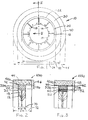
- Figure 1 is a schematic side planned of a wheel and solid rubber tire assembly 10, having a metallic wheel 12 with an inner hub opening 14, a bolt pattern 16 for connection to a construction vehicle hub support ribs 18 spaced radially around the wheel and supportingly fastened to a cylindrical rim 20.
- Figure 2 depicts a partial cross-section of a wheel 10 according to one embodiment viewed at the position of section line II.2 of Figure 1.
- the width W of the rim 20 and narrow inner layer 30 is approximately one-half the width 2W of the wear layer 40.
- the inner layer 30 is bonded directly to the rim 20 at surface 22 which corresponds to the rim diameter 24 of Figure 1 and the wear layer 40 is bonded directly to cylindrical surface 32 of continuous inner layer 30 which surface 32 corresponds to diameter 34 of Figure 1.
- the thickness 36 of inner layer 30 is in the range of about 2-6 inches and the thickness 46 of the wear layers in the range of about 7-12 inches.
- Figure 3 depicts an alternative preferred embodiment of a partial cross-section of a wheel and solid rubber tire assembly according to the present invention again with the width of layer 30 approximately one-half the width of narrow soft layer of rubber 30, approximately one-half the width of wide wear layer of rubber boarding fording.
- a hard rubber primer layer 50 is provided bonded to the rim and to the inner layer there between at diameter 24 of the rim.
- the thickness of primer layer 50 made the thickness 52 of primer layer 50 may be in the range of 3/4ths of an inch to one and one-half inches.
- the hardness of primer layer 50 may advantageously be in the range of about 75-85 Durometer (Scores A scale).
- a bonding layer 60 bonded between soft inner layer 30 and wider wear layer 40 at diameter 34.
- the thickness 62 of bonding layer 60 is in the range of between about 3/4" and 1-1/2" and the hardness is advantageously in the range of between about 75-85 Durometer (Scores A scale).
- the thickness 38 of wear layer 30 may be less than thickness 36 as with the embodiment in Figure 2 and the thickness 48 of wear layer 40 may be less than the thickness 46 of wear layer 40 in the embodiment of Figure 2.
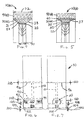
- Figure 4 depicts the embodiment of the invention in which the soft inner layer 30(c) includes angled sides 31 and 33 which expand the width of soft inner layer 30 from the interior narrow width 70 of rim 20 to the wider width 72 of wear layer 40(c).
- increased durability is obtained with the angled transition from the narrow width 70 to the wider width 72 and increased compression flexibility is still maintained because of the reduced support area on surface 22 of rim 20.
- Figure 5 depicts yet another preferred alternative embodiment in which soft inner layer 30(d) is coupled between rim 20 with a hard primer layer 50. Further, soft inner layer 30(d) is provided with concave curved sides 35 and 37 expanding from narrow width 70 to wider width 72. Also bonded between layer 30(d) and wear layer 40(d) is the bonding layer 60 of hard rubber.
- Figure 6 is a schematic depiction of a wheel and solid rubber assembly in which a soft inner core 80 is provided surrounded by harder side portions 82 and 84 and a wear layer 86 according previously known construction in such previous construction there was also a rim 90 had projections 92 and 94 on either side extending at least partially up the sidewalls of side sections 80 and 84.
- Rim 90 is supported from the vehicle along axis 96. Upon rolling along the surface 100 the entire solid rubber tire is compressed slightly and upon impacting an obstacle 102, the height 104 of obstacle 102 must be accommodated by either compression of the solid rubber or raising of the axle.
- the solid rubber may compress to a small degree so that the interface between the hard rubber layer 86 and the core 82, 84 move to a lesser amount 106 than the distance 104 and additional compression of layer 82, 80 and 84 cause the rim 90 to move even a smaller amount 108 which distance 108 was translated directly to movement of the axle, a distance 108.
- the distance 108 was only slightly less than the distance 104 or the obstacle causing a bumpy, rough ride.
- FIG. 7 is a schematic depiction of a rim and solid rubber tire according to the present invention
- impact of the wheel with the same obstacle 102 requires the wheel to accommodate a height 104.
- the wear layer 40 compresses only slightly so that the interface between the wear layer 40 and the narrow inner layer 30 moves a distance 106 which is substantially equivalent to the distance of the previous device shown in Figure 6.
- the increased compensability of soft inner layer 30 accommodate almost the entire movement distance 106 such that the movement distance 110 of rim 20 is about one-half the movement distance 108 as would be experienced with the construction of Figure 6.
- the movement of the axle 110 is reduced by about one-half, thereby smoothing the ride substantially.
Landscapes
- Engineering & Computer Science (AREA)
- Mechanical Engineering (AREA)
- Tires In General (AREA)
Abstract
Description
- This invention relates to heavy equipment wheels and solid rubber tires and the method of forming same, and particularly to a durable, smooth riding solid rubber tire with consistent soft rubber cushion support around the entire circumference of the tire.
- In the construction industry, heavy rolling equipment has advantageously used flat-proof, solid rubber, low profile tires on constructed to avoid slippage on metal wheel rims.
- This construction advantageously avoided difficulties with punctured pneumatic tires or "flats" and also avoided the excessive weight and increased wear and breakdown of standard pneumatic tires filled with fluid rubber, elastomeric or urethane form material, which solidified in the tires to avoid flats. Downtime was reduced and cost-effective, economic usage in many applications for heavy equipment previously dominated with pneumatic tires proved such tires highly reliable and important in the industry. Particularly, for example, underground mining applications where downtime for changing pneumatic tires is extremely expensive, such rubber tires have become very important. Junkyard or metal yards or scrap metal facilities where puncturing of pneumatic tires is of prime concern, such solid rubber tires for large construction equipment have become important industry components.
- Innovations in the area of wheel and solid rubber tire technology have been demonstrated in U.S. Patent No. 4,966,212, issued to Giles Hill, October 30, 1990 for a wheel and tire assembly with a solid rubber tire for use on heavy construction equipment. The assembly included a mounting disk, a large diameter rim having a circular surface rigidly affixed to the mounting disk, and having axially-opposed peripheral sides. Cross-ribs were rigidly fastened to the cylindrical surface of the rim across the cylindrical rim surface. Metal side support rims were rigidly affixed to and radially projecting from the peripheral side of the cylindrical rim surface. A base layer of even thickness of substantially flat rubber was submitted to the cylindrical surface, interposed between the cross-ribs and the side support rims. Multiple additional layers of even thickness of substantially flat sheet rubber were bonded to the base layer, and each succeeding additional layer was bonded to the preceding additional layer until a low profile, solid rubber tire was obtained. The solid rubber tire was thus bonded directly to the large diameter wheel rim for use on heavy construction equipment.
- An improved method of constructing a wheel and low profile solid rubber tire was disclosed in U.S. Patent No. 5,053,095, issued to Giles Hill, October 1, 1991, for an improved method of constructing a wheel and tire assembly with a solid rubber tire for use on heavy construction equipment. The method included a mounting disk, a large diameter rim having a cylindrical surface and axially-opposed peripheral sides attached to the mounting rim. Cross ribs were rigidly fastened to and laterally across a cylindrical surface. There were side supporting rims rigidly affixed and radially projecting from the peripheral side of the cylindrical rim surfaces. A base layer of even thickness of substantially flat rubber was cemented to the cylindrical surface interposed between the cross rib and the side support rims. Multiple additional layers of even thickness substantially flat rubber were bonded to the base layer and each succeeding layer of even thickness was bonded to the preceding additional layer.
- In both U.S. Patents No. 4,966,212 and 5,053,095, it was contemplated that an interior core of a plurality of layers sequentially bonded rubber could include a softer rubber material surrounded on both sides by harder rubber sidewalls. The soft rubber core was designed to increase the flexibility of the solid rubber tire. However, in practice the increase in flexibility and cushioning of the ride due to the solid rubber core was significantly offset by the increased cost of producing sequential layers having side portions of one hardness rubber and a central portion of softer rubber. For this reason, such soft core solid rubber tires have not yet gained wide acceptance in the marketplace.
- Previous attempts to smooth the ride have included putting air pockets or holes in the rubber below the wear layer or the tread layer thereby reducing the amount of rubber absorbing the impact between the outer wear layer and the rim. These attempts have provided some cushioning and have met with some success relative to other solid rubber tires. However, as the tread wears down there can be uneven support for the wear layer depending upon whether there is an air pocket or a web or spoke of rubber extended between the rim and the wear layer. This can lead to ripples developing in the tire when the tread wears thin.
- These and other disadvantages of the prior art have been overcome in the present invention by providing a narrow cylindrical rim, a layer of soft, durable rubber continuously formed, attached or bonded to the rim around the entire circumference also having a portion thereof with a width approximately corresponding to the narrow width of the wheel rim, and a wear layer of solid rubber attached or bonded entirely around the outer circumference of the softer rubber layer and substantially wider than the rim and that portion of the softer rubber tire having a width corresponding to the rim so that the entire width of the wear layer provides the desired traction and load carrying capability for the tire on heavy construction equipment and the narrower soft rubber portion acts to carry the entire load and therefore has increased amounts of compression because of the reduced area of softer rubber carrying the load applied to the larger area of the harder wear rubber.
- According to this invention, a solid rubber tire and wheel assembly can be made with an improved structure to provide greater cushioning that previous solid rubber tires while maintaining good wear characteristics. It has been found that the soft inner core surrounded by harder rubber in a solid rubber tire provides some cushioning effect as was described in earlier U.S. Patents No. 4,966,212 and 5,053,095 issued to Giles Hill. It has recently been discovered that a greater degree of movement of the outer layer can be obtained if the entire outer layer pushes on a smaller area of soft inner core. It is theorized that because all of the weight is carried by the smaller area of softer rubber, the total distance of compression is greater. This provides greater bump impact-absorbing characteristics and smooths the ride significantly. The present invention can approach the riding smoothness of a pneumatic tire while eliminating punctures and the costly downtime associated with changing pneumatic tires on large tractors and other construction equipment. No ripples develop when the wear layer wears very thin.
- The present invention therefore accomplishes a smoother ride uniquely by providing a continuous inner softer layer of rubber but which core has a reduced width so that the surface area of the wear layer is substantially greater than the surface area of the softer inner layer. Thus, the width of the metallic rim is reduced and an inner rubber layer of about 25-35 Durometer (Scores A scale) extends across the reduced width and may also have tapered or angled sides expanding outward to where the soft rubber layer connects and is bonded to a wider wear layer of rubber. The outer wear layer is much wider than the rim and thus provides the ground contact area required for effective traction. The wear layer may be in the range of 60-70 Durometer (Scores A scale).
- In an alternative embodiment of the invention and to further provide significant strength of bonding between the continuous narrow soft rubber layer and the metal rim, a primer layer of hard rubber, which may be in the range of 75-95 Durometer (Scores A scale), is bonded between the rim and the soft inner layer. A wider bonding layer of hard rubber is bonded between the narrow soft inner layer and the wider outer wear layer. The bonding layer is also preferably in a range of about 75-85 Durometer (Scores A scale).
- In one particular embodiment for example, the rim, the primer layer and the narrow soft rubber are about 11-12 inches wide and the bonding layer of hard rubber and the wear layer are about 23-24 inches wide. It has been found that the width of the wear layer at about two times the width of the rim effectively reduces the area of contact of the soft inner layer, allowing it to compress under normal loading about two times as much as a softer rubber on a rim which has the same width as the wear layer. Because the soft layer is continuously compressed about two times as much as normal, the range of movement under impact with bumps and debris is also about two times as much, so that the bumping movement at the axle of the vehicle upon impact with an object is reduced by about one-half, thereby significantly smoothing the ride.
- These and other objects and advantages of the invention may be more fully understood with reference to the following detailed description, claims and drawings in which drawings, like numerals, represent like element and in which:
- Figure 1 is a side schematic view of a wheel rim and solid rubber tire according to the present invention;
- Figure 2 is a partial cross-sectional view of one embodiment of a wheel and tire assembly according to the invention viewed along a cross-section schematically shown at section line II-II of Figure 1;
- Figure 3 is a partial cross-sectional view of an alternative embodiment of a wheel and solid rubber tire assembly viewed along a cross-section schematically shown at section line II-II of Figure 1;
- Figure 4 is a partial cross-sectional view of another alternative embodiment of the invention viewed along a cross-section schematically shown at section line II-II of Figure 1;
- Figure 5 is a partial cross-sectional view of yet another alternative embodiment of the invention;
- Figure 6 is a schematic depiction of a comparative model of a conceptual wheel and solid rubber tire assembly with a soft rubber core and harder side and tread portions rolling over a bump; and
- Figure 7 is a schematic depiction of flexure characteristics of a wheel and tire assembly according to an embodiment of the invention for comparison to the conceptual wheel and the assembly of Figure 6.
-
- Figure 1 is a schematic side planned of a wheel and solid
rubber tire assembly 10, having ametallic wheel 12 with an inner hub opening 14, abolt pattern 16 for connection to a construction vehiclehub support ribs 18 spaced radially around the wheel and supportingly fastened to acylindrical rim 20. There is an inner layer of continuoussoft rubber 30 securely connected to theexterior surface 22 ofrim 20 at apredetermined diameter 24. There is also a wide wear layer ofrubber 40, having a width substantially greater than the width of the narrowsoft rubber layer 30 and having a hardness that is significantly harder than the softnarrow rubber layer 30.Wear layer 40 is securely attached continuously around the perimeter atpredetermined diameter 32 of narrowinner layer 30. - Figure 2 depicts a partial cross-section of a
wheel 10 according to one embodiment viewed at the position of section line II.2 of Figure 1. In the embodiment shown in Figure 2 indicates that the width W of therim 20 and narrowinner layer 30 is approximately one-half the width 2W of thewear layer 40. Theinner layer 30 is bonded directly to therim 20 atsurface 22 which corresponds to therim diameter 24 of Figure 1 and thewear layer 40 is bonded directly tocylindrical surface 32 of continuousinner layer 30 whichsurface 32 corresponds todiameter 34 of Figure 1. Thethickness 36 ofinner layer 30 is in the range of about 2-6 inches and thethickness 46 of the wear layers in the range of about 7-12 inches. - Figure 3 depicts an alternative preferred embodiment of a partial cross-section of a wheel and solid rubber tire assembly according to the present invention again with the width of
layer 30 approximately one-half the width of narrow soft layer ofrubber 30, approximately one-half the width of wide wear layer of rubber boarding fording. In this embodiment to facilitate bonding between the narrow softinner layer 30 and therim 20, a hardrubber primer layer 50 is provided bonded to the rim and to the inner layer there between atdiameter 24 of the rim. The thickness ofprimer layer 50 made thethickness 52 ofprimer layer 50 may be in the range of 3/4ths of an inch to one and one-half inches. The hardness ofprimer layer 50 may advantageously be in the range of about 75-85 Durometer (Scores A scale). Also depicted in the embodiment of Figure 3 in the embodiment of wheel and tire assembly 10(b) of Figure 3 is abonding layer 60 bonded between softinner layer 30 andwider wear layer 40 atdiameter 34. Thethickness 62 ofbonding layer 60 is in the range of between about 3/4" and 1-1/2" and the hardness is advantageously in the range of between about 75-85 Durometer (Scores A scale). To maintain the samemaximum diameter 44, either therim diameter 24 may be reduced or, alternatively, thethickness 38 ofwear layer 30 may be less thanthickness 36 as with the embodiment in Figure 2 and the thickness 48 ofwear layer 40 may be less than thethickness 46 ofwear layer 40 in the embodiment of Figure 2. - Figure 4 depicts the embodiment of the invention in which the soft inner layer 30(c) includes angled
sides inner layer 30 from the interiornarrow width 70 ofrim 20 to thewider width 72 of wear layer 40(c). In this embodiment increased durability is obtained with the angled transition from thenarrow width 70 to thewider width 72 and increased compression flexibility is still maintained because of the reduced support area onsurface 22 ofrim 20. - Figure 5 depicts yet another preferred alternative embodiment in which soft inner layer 30(d) is coupled between
rim 20 with ahard primer layer 50. Further, soft inner layer 30(d) is provided with concavecurved sides narrow width 70 towider width 72. Also bonded between layer 30(d) and wear layer 40(d) is thebonding layer 60 of hard rubber. - With reference to both Figures 6 and 7 in which Figure 6 is a schematic depiction of a wheel and solid rubber assembly in which a soft inner core 80 is provided surrounded by harder side portions 82 and 84 and a
wear layer 86 according previously known construction in such previous construction there was also arim 90 hadprojections Rim 90 is supported from the vehicle alongaxis 96. Upon rolling along thesurface 100 the entire solid rubber tire is compressed slightly and upon impacting anobstacle 102, theheight 104 ofobstacle 102 must be accommodated by either compression of the solid rubber or raising of the axle. With the inner core and compensability of the rubber tire, the solid rubber may compress to a small degree so that the interface between thehard rubber layer 86 and the core 82, 84 move to alesser amount 106 than thedistance 104 and additional compression of layer 82, 80 and 84 cause therim 90 to move even asmaller amount 108 whichdistance 108 was translated directly to movement of the axle, adistance 108. In the circumstances depicted with the prior construction, thedistance 108 was only slightly less than thedistance 104 or the obstacle causing a bumpy, rough ride. - Turning now to Figure 7 which is a schematic depiction of a rim and solid rubber tire according to the present invention, impact of the wheel with the
same obstacle 102 requires the wheel to accommodate aheight 104. Thewear layer 40 compresses only slightly so that the interface between thewear layer 40 and the narrowinner layer 30 moves adistance 106 which is substantially equivalent to the distance of the previous device shown in Figure 6. However, the increased compensability of softinner layer 30 accommodate almost theentire movement distance 106 such that themovement distance 110 ofrim 20 is about one-half themovement distance 108 as would be experienced with the construction of Figure 6. Thus the movement of theaxle 110 is reduced by about one-half, thereby smoothing the ride substantially. - Other alterations and modifications of the invention will likewise become apparent to those of ordinary skill in the art upon reading the present disclosure, and it is intended that the scope of the invention disclosed herein be limited only by the broadest interpretation of the appended claims to which the inventors are legally entitled.
Claims (10)
- A wheel a solid rubber tire comprising:a. a metal wheel having a predetermined diameter and a cylindrical rim around the periphery of said metal wheel, said rim having a predetermined narrow width;b. a soft layer of rubber secured to said narrow rim, having a first diameter and a first width at said first diameter, said first width approximately equal to said narrow width of said rim, said soft layer of rubber secured to said rim, and further having a second diameter larger than said first diameter; andc. a wear layer of solid rubber having a width substantially greater than said narrow width of said rim and soft layer, said wear layer bonded to said soft layer at said second diameter, and said wear layer having a maximum diameter greater than said second diameter of said soft layer of rubber.
- A wheel and solid rubber tire assembly as in Claim 1, further comprising:a. a primer layer of hard rubber at said first diameter bonded between said cylindrical rim and said soft narrow layer; andb. a second bonding layer of hard rubber at said second diameter bonded between said soft narrow layer and said wide wear layer.
- A wheel and solid rubber tire assembly as in Claim 1 wherein said first narrow layer of soft rubber has said first narrow width at said rim and has a second width at said second diameter, at which second diameter said narrow soft layer is bonded to said wide wear layer.
- A wheel and solid rubber tire assembly as in Claim 1 wherein said soft layer comprises a rubber material having a uniform hardness in the range of about 25-40 Durometer (measured on the Scores A scale at room temperature) and said wide wear layer has a uniform hardness in the range of between about 60 and 70 Durometer (measured on the Scores A scale at room temperature).
- A wheel and solid rubber tire as in Claim 2 wherein said narrow layer rubber has a uniform hardness in the range of 25-40 Durometer (Scores A scale);a. said wear layer has a uniform hardness in the range of between 60 and 70 Durometer (Scores A scale); andb. said primer layer and said bonding layer each have a uniform hardness in the range of between about 75-85 Durometer (Scores A scale).
- A wheel and solid rubber tire assembly as in Claim 1 wherein said width of said rim and also of said narrow soft rubber layer is predetermined at approximately two inches per 1,000-pound maximum load carrying capacity of said wheel and tire assembly (so that an 8-inch wide narrow layer has a maximum load of 4,000 pounds) and said wider width of said wear layer is approximately four inches per 1,000-pound load carrying capacity of said wheel and tire assembly (so that a 16-inch wide wear layer also has a maximum load of 4,000 pounds).
- A wheel and solid rubber tire assembly as in Claim 1 wherein said predetermined width of said rim and narrow layer is approximately one-half of said predetermined width of said wear layer.
- A wheel and solid rubber tire assembly as in Claim 1, Claim 2, or Claim 3 wherein said narrow soft rubber layer extends continuously around the periphery of the tire.
- A wheel and solid rubber tire assembly as in Claim 1, 2 or 3 wherein said narrow layer of rubber is free to expand its width upon compression up to about one and one-half times said predetermined first width of said narrow layer of soft rubber.
- A wheel and solid rubber tire assembly as in Claims 1, 2 or 3 wherein:a. said narrow soft inner layer has a thickness in the range of about 6-8 inches; andb. said side wear layer has a thickness in the range of about 9-11 inches.
Applications Claiming Priority (2)
| Application Number | Priority Date | Filing Date | Title |
|---|---|---|---|
| US09/086,198 US6089292A (en) | 1998-05-28 | 1998-05-28 | Durable, smooth ride wheel and solid rubber tire |
| US86198 | 1998-05-28 |
Publications (2)
| Publication Number | Publication Date |
|---|---|
| EP0960748A2 true EP0960748A2 (en) | 1999-12-01 |
| EP0960748A3 EP0960748A3 (en) | 2001-05-16 |
Family
ID=22196937
Family Applications (1)
| Application Number | Title | Priority Date | Filing Date |
|---|---|---|---|
| EP99250163A Withdrawn EP0960748A3 (en) | 1998-05-28 | 1999-05-25 | Durable, smooth ride wheel and solid rubber tire |
Country Status (3)
| Country | Link |
|---|---|
| US (1) | US6089292A (en) |
| EP (1) | EP0960748A3 (en) |
| CA (1) | CA2272108C (en) |
Cited By (2)
| Publication number | Priority date | Publication date | Assignee | Title |
|---|---|---|---|---|
| EP1262301A2 (en) * | 2001-05-31 | 2002-12-04 | Colson Castors Limited | Wheels for transportation vehicles |
| CN105034701A (en) * | 2015-05-22 | 2015-11-11 | 深圳市道尔轮胎科技有限公司 | Tire-burst-free polyurethane hand cart tire with elastic inserting member |
Families Citing this family (8)
| Publication number | Priority date | Publication date | Assignee | Title |
|---|---|---|---|---|
| US20020096237A1 (en) | 2001-01-23 | 2002-07-25 | Burhoe John Charles Alexander | Compliant rim and wheel and assembly |
| US8757228B2 (en) | 2010-03-30 | 2014-06-24 | Drew J. Dutton | Interlocking compressible, paired spoke wheel system |
| US9302539B2 (en) | 2012-04-25 | 2016-04-05 | Lindsay Corporation | Wheel and tire assembly |
| US9090121B2 (en) | 2012-04-25 | 2015-07-28 | Lindsey Corporation | Wheel and tire assembly |
| US9266506B2 (en) | 2012-04-25 | 2016-02-23 | Lindsay Corporation | Wheel and tire assembly with adjustable spacer system |
| US9242510B2 (en) | 2012-09-24 | 2016-01-26 | Lindsay Corporation | Wheel and tire assembly and method of assembly |
| US9186934B2 (en) | 2012-09-24 | 2015-11-17 | Lindsay Corporation | Wheel and tire assembly |
| KR101252035B1 (en) * | 2013-01-23 | 2013-06-04 | 김영진 | Non-pneumatic tire with wheel and manufacturing method thereof |
Citations (5)
| Publication number | Priority date | Publication date | Assignee | Title |
|---|---|---|---|---|
| US1370442A (en) * | 1920-10-01 | 1921-03-01 | Harold M Henry | Vehicle-tire |
| GB2012686A (en) * | 1977-11-28 | 1979-08-01 | Bergougnan Benelux | Solid tyres |
| GB2183565A (en) * | 1985-11-27 | 1987-06-10 | Vinaflex Limited | Non pneumatic tyres |
| US5265659A (en) * | 1992-03-18 | 1993-11-30 | Uniroyal Goodrich Licensing Services, Inc. | Non-pneumatic tire with ride-enhancing insert |
| US5429165A (en) * | 1991-07-19 | 1995-07-04 | Sumitomo Rubber Industries | Pneumatic-shaped solid tire |
Family Cites Families (23)
| Publication number | Priority date | Publication date | Assignee | Title |
|---|---|---|---|---|
| US859078A (en) * | 1906-04-05 | 1907-07-02 | Kempshall Tire Company | Tire. |
| US991737A (en) * | 1908-09-08 | 1911-05-09 | Theodore Koop | Automobile-tire. |
| US1104783A (en) * | 1914-03-26 | 1914-07-28 | Walter Drabold | Tire. |
| US1232275A (en) * | 1916-02-14 | 1917-07-03 | Joseph S Stringham | Vehicle-wheel. |
| US1246756A (en) * | 1916-11-18 | 1917-11-13 | George Washington Kitterman | Vehicle-wheel. |
| US1263947A (en) * | 1917-10-16 | 1918-04-23 | William Shomer | Composite cushioning non-inflatable tire. |
| US1424134A (en) * | 1918-09-21 | 1922-07-25 | Goodyear Tire & Rubber | Method of building tires of the solid type |
| US1301230A (en) * | 1918-11-02 | 1919-04-22 | James H Cooper | Tire. |
| US1399180A (en) * | 1921-03-14 | 1921-12-06 | Fred L Bailey | Core for tire-casings |
| US1544639A (en) * | 1923-12-05 | 1925-07-07 | Hood Rubber Co Inc | Cushion tire |
| US1499809A (en) * | 1923-12-06 | 1924-07-01 | Duke Harold Hill | Disk wheel for motor and other road vehicles |
| US1591982A (en) * | 1925-03-18 | 1926-07-13 | William R Kirkwood | Demountable cushion tire |
| US1867438A (en) * | 1931-10-23 | 1932-07-12 | Baeck Adolph | Tire |
| US2709471A (en) * | 1950-04-28 | 1955-05-31 | Us Rubber Co | Solid tire and method of making same |
| US2896687A (en) * | 1954-11-10 | 1959-07-28 | Us Rubber Co | Tire and wheel assembly |
| US2882950A (en) * | 1956-03-01 | 1959-04-21 | William G Grove | Vehicle tire |
| US2955637A (en) * | 1957-10-01 | 1960-10-11 | Hartzmark Alan | Press lock ring for laminated tires |
| US3018809A (en) * | 1959-11-10 | 1962-01-30 | Jules E Briche | Flexible non-pneumatic tire |
| DE2851765A1 (en) * | 1978-11-30 | 1980-06-04 | Bayer Ag | TIRES FOR HIGH PAYLOADS |
| US4921029A (en) * | 1984-04-16 | 1990-05-01 | The Uniroyal Goodrich Tire Company | Trapezoidal non-pneumatic tire with supporting and cushioning members |
| US4966212A (en) * | 1988-08-05 | 1990-10-30 | Giles Hill | Wheel and solid rubber tire assembly and method |
| US5053095A (en) * | 1988-08-05 | 1991-10-01 | Giles Hill | Method for constructing a wheel and low profile solid rubber tire |
| JP2731489B2 (en) * | 1992-07-01 | 1998-03-25 | 住友ゴム工業株式会社 | Solid tire |
-
1998
- 1998-05-28 US US09/086,198 patent/US6089292A/en not_active Expired - Lifetime
-
1999
- 1999-05-17 CA CA002272108A patent/CA2272108C/en not_active Expired - Fee Related
- 1999-05-25 EP EP99250163A patent/EP0960748A3/en not_active Withdrawn
Patent Citations (5)
| Publication number | Priority date | Publication date | Assignee | Title |
|---|---|---|---|---|
| US1370442A (en) * | 1920-10-01 | 1921-03-01 | Harold M Henry | Vehicle-tire |
| GB2012686A (en) * | 1977-11-28 | 1979-08-01 | Bergougnan Benelux | Solid tyres |
| GB2183565A (en) * | 1985-11-27 | 1987-06-10 | Vinaflex Limited | Non pneumatic tyres |
| US5429165A (en) * | 1991-07-19 | 1995-07-04 | Sumitomo Rubber Industries | Pneumatic-shaped solid tire |
| US5265659A (en) * | 1992-03-18 | 1993-11-30 | Uniroyal Goodrich Licensing Services, Inc. | Non-pneumatic tire with ride-enhancing insert |
Cited By (4)
| Publication number | Priority date | Publication date | Assignee | Title |
|---|---|---|---|---|
| EP1262301A2 (en) * | 2001-05-31 | 2002-12-04 | Colson Castors Limited | Wheels for transportation vehicles |
| EP1262301A3 (en) * | 2001-05-31 | 2003-07-16 | Colson Castors Limited | Wheels for transportation vehicles |
| CN105034701A (en) * | 2015-05-22 | 2015-11-11 | 深圳市道尔轮胎科技有限公司 | Tire-burst-free polyurethane hand cart tire with elastic inserting member |
| CN105034701B (en) * | 2015-05-22 | 2017-08-11 | 深圳市道尔轮胎科技有限公司 | A kind of polyurethane hand cart tyre of not blowing out with elastic plugin |
Also Published As
| Publication number | Publication date |
|---|---|
| US6089292A (en) | 2000-07-18 |
| CA2272108A1 (en) | 1999-11-28 |
| EP0960748A3 (en) | 2001-05-16 |
| CA2272108C (en) | 2008-10-14 |
Similar Documents
| Publication | Publication Date | Title |
|---|---|---|
| EP2066502B1 (en) | Variable stiffness spoke for a non-pneumatic assembly | |
| CA2525982C (en) | Non-pneumatic tire | |
| KR101059722B1 (en) | Compliant wheel | |
| US11090974B2 (en) | Shear deforming non-pneumatic tire spokes | |
| US7418988B2 (en) | Non-pneumatic tire | |
| US4082132A (en) | Low section profile pneumatic radial tire for heavy vehicles | |
| JP4855646B2 (en) | Non-pneumatic tire | |
| EP2686174B1 (en) | Non-pneumatic tire with annular spoke reinforcement | |
| JP2589399B2 (en) | Non-air filled tire with trapezoidal cross section | |
| US20140062168A1 (en) | Non-pneumatic tire | |
| US20140062171A1 (en) | Non-pneumatic tire | |
| AU2013308598A1 (en) | Non-pneumatic tire | |
| US20140062169A1 (en) | Non-pneumatic tire | |
| US20140062170A1 (en) | Non-pneumatic tire | |
| US20140062172A1 (en) | Non-pneumatic tire | |
| US6089292A (en) | Durable, smooth ride wheel and solid rubber tire | |
| US6941990B2 (en) | Off-road tires having sidewall anti-puncture pads | |
| US5053095A (en) | Method for constructing a wheel and low profile solid rubber tire | |
| US4966212A (en) | Wheel and solid rubber tire assembly and method | |
| US5313994A (en) | Solid rubber wheel and tire assembly with angled cross bars | |
| US5620235A (en) | Vehicle wheel | |
| US20030173010A1 (en) | Pneumatic tire, for vehicles | |
| US5957494A (en) | Apparatus and method for improving the lateral stability of vehicles | |
| JP3472398B2 (en) | No flat tire | |
| JPS6157402A (en) | Pneumatic tire type car wheel |
Legal Events
| Date | Code | Title | Description |
|---|---|---|---|
| PUAI | Public reference made under article 153(3) epc to a published international application that has entered the european phase |
Free format text: ORIGINAL CODE: 0009012 |
|
| AK | Designated contracting states |
Kind code of ref document: A2 Designated state(s): AT BE CH CY DE DK ES FI FR GB GR IE IT LI LU MC NL PT SE |
|
| AX | Request for extension of the european patent |
Free format text: AL;LT;LV;MK;RO;SI |
|
| PUAL | Search report despatched |
Free format text: ORIGINAL CODE: 0009013 |
|
| AK | Designated contracting states |
Kind code of ref document: A3 Designated state(s): AT BE CH CY DE DK ES FI FR GB GR IE IT LI LU MC NL PT SE |
|
| AX | Request for extension of the european patent |
Free format text: AL;LT;LV;MK;RO;SI |
|
| AKX | Designation fees paid | ||
| REG | Reference to a national code |
Ref country code: DE Ref legal event code: 8566 |
|
| STAA | Information on the status of an ep patent application or granted ep patent |
Free format text: STATUS: THE APPLICATION IS DEEMED TO BE WITHDRAWN |
|
| 18D | Application deemed to be withdrawn |
Effective date: 20011117 |