EP0960700A1 - Apparatus for forming a circumferential score in a plastic closure - Google Patents
Apparatus for forming a circumferential score in a plastic closure Download PDFInfo
- Publication number
- EP0960700A1 EP0960700A1 EP99116034A EP99116034A EP0960700A1 EP 0960700 A1 EP0960700 A1 EP 0960700A1 EP 99116034 A EP99116034 A EP 99116034A EP 99116034 A EP99116034 A EP 99116034A EP 0960700 A1 EP0960700 A1 EP 0960700A1
- Authority
- EP
- European Patent Office
- Prior art keywords
- knife
- turret
- closure
- block
- rotation
- Prior art date
- Legal status (The legal status is an assumption and is not a legal conclusion. Google has not performed a legal analysis and makes no representation as to the accuracy of the status listed.)
- Withdrawn
Links
Images


Classifications
-
- B—PERFORMING OPERATIONS; TRANSPORTING
- B26—HAND CUTTING TOOLS; CUTTING; SEVERING
- B26D—CUTTING; DETAILS COMMON TO MACHINES FOR PERFORATING, PUNCHING, CUTTING-OUT, STAMPING-OUT OR SEVERING
- B26D7/00—Details of apparatus for cutting, cutting-out, stamping-out, punching, perforating, or severing by means other than cutting
- B26D7/26—Means for mounting or adjusting the cutting member; Means for adjusting the stroke of the cutting member
- B26D7/2628—Means for adjusting the position of the cutting member
-
- B—PERFORMING OPERATIONS; TRANSPORTING
- B26—HAND CUTTING TOOLS; CUTTING; SEVERING
- B26D—CUTTING; DETAILS COMMON TO MACHINES FOR PERFORATING, PUNCHING, CUTTING-OUT, STAMPING-OUT OR SEVERING
- B26D3/00—Cutting work characterised by the nature of the cut made; Apparatus therefor
- B26D3/08—Making a superficial cut in the surface of the work without removal of material, e.g. scoring, incising
-
- B—PERFORMING OPERATIONS; TRANSPORTING
- B26—HAND CUTTING TOOLS; CUTTING; SEVERING
- B26D—CUTTING; DETAILS COMMON TO MACHINES FOR PERFORATING, PUNCHING, CUTTING-OUT, STAMPING-OUT OR SEVERING
- B26D7/00—Details of apparatus for cutting, cutting-out, stamping-out, punching, perforating, or severing by means other than cutting
- B26D7/01—Means for holding or positioning work
- B26D7/02—Means for holding or positioning work with clamping means
-
- B—PERFORMING OPERATIONS; TRANSPORTING
- B26—HAND CUTTING TOOLS; CUTTING; SEVERING
- B26F—PERFORATING; PUNCHING; CUTTING-OUT; STAMPING-OUT; SEVERING BY MEANS OTHER THAN CUTTING
- B26F2210/00—Perforating, punching, cutting-out, stamping-out, severing by means other than cutting of specific products
- B26F2210/04—Making plastic pilferproof screw caps by cutting a tamper ring
-
- Y—GENERAL TAGGING OF NEW TECHNOLOGICAL DEVELOPMENTS; GENERAL TAGGING OF CROSS-SECTIONAL TECHNOLOGIES SPANNING OVER SEVERAL SECTIONS OF THE IPC; TECHNICAL SUBJECTS COVERED BY FORMER USPC CROSS-REFERENCE ART COLLECTIONS [XRACs] AND DIGESTS
- Y10—TECHNICAL SUBJECTS COVERED BY FORMER USPC
- Y10T—TECHNICAL SUBJECTS COVERED BY FORMER US CLASSIFICATION
- Y10T82/00—Turning
- Y10T82/16—Severing or cut-off
- Y10T82/16016—Processes
-
- Y—GENERAL TAGGING OF NEW TECHNOLOGICAL DEVELOPMENTS; GENERAL TAGGING OF CROSS-SECTIONAL TECHNOLOGIES SPANNING OVER SEVERAL SECTIONS OF THE IPC; TECHNICAL SUBJECTS COVERED BY FORMER USPC CROSS-REFERENCE ART COLLECTIONS [XRACs] AND DIGESTS
- Y10—TECHNICAL SUBJECTS COVERED BY FORMER USPC
- Y10T—TECHNICAL SUBJECTS COVERED BY FORMER US CLASSIFICATION
- Y10T82/00—Turning
- Y10T82/16—Severing or cut-off
- Y10T82/16426—Infeed means
- Y10T82/16967—Infeed means with means to support and/or rotate work
-
- Y—GENERAL TAGGING OF NEW TECHNOLOGICAL DEVELOPMENTS; GENERAL TAGGING OF CROSS-SECTIONAL TECHNOLOGIES SPANNING OVER SEVERAL SECTIONS OF THE IPC; TECHNICAL SUBJECTS COVERED BY FORMER USPC CROSS-REFERENCE ART COLLECTIONS [XRACs] AND DIGESTS
- Y10—TECHNICAL SUBJECTS COVERED BY FORMER USPC
- Y10T—TECHNICAL SUBJECTS COVERED BY FORMER US CLASSIFICATION
- Y10T83/00—Cutting
- Y10T83/02—Other than completely through work thickness
- Y10T83/0207—Other than completely through work thickness or through work presented
- Y10T83/023—With infeeding of work
-
- Y—GENERAL TAGGING OF NEW TECHNOLOGICAL DEVELOPMENTS; GENERAL TAGGING OF CROSS-SECTIONAL TECHNOLOGIES SPANNING OVER SEVERAL SECTIONS OF THE IPC; TECHNICAL SUBJECTS COVERED BY FORMER USPC CROSS-REFERENCE ART COLLECTIONS [XRACs] AND DIGESTS
- Y10—TECHNICAL SUBJECTS COVERED BY FORMER USPC
- Y10T—TECHNICAL SUBJECTS COVERED BY FORMER US CLASSIFICATION
- Y10T83/00—Cutting
- Y10T83/02—Other than completely through work thickness
- Y10T83/0333—Scoring
- Y10T83/0341—Processes
-
- Y—GENERAL TAGGING OF NEW TECHNOLOGICAL DEVELOPMENTS; GENERAL TAGGING OF CROSS-SECTIONAL TECHNOLOGIES SPANNING OVER SEVERAL SECTIONS OF THE IPC; TECHNICAL SUBJECTS COVERED BY FORMER USPC CROSS-REFERENCE ART COLLECTIONS [XRACs] AND DIGESTS
- Y10—TECHNICAL SUBJECTS COVERED BY FORMER USPC
- Y10T—TECHNICAL SUBJECTS COVERED BY FORMER US CLASSIFICATION
- Y10T83/00—Cutting
- Y10T83/04—Processes
- Y10T83/0596—Cutting wall of hollow work
-
- Y—GENERAL TAGGING OF NEW TECHNOLOGICAL DEVELOPMENTS; GENERAL TAGGING OF CROSS-SECTIONAL TECHNOLOGIES SPANNING OVER SEVERAL SECTIONS OF THE IPC; TECHNICAL SUBJECTS COVERED BY FORMER USPC CROSS-REFERENCE ART COLLECTIONS [XRACs] AND DIGESTS
- Y10—TECHNICAL SUBJECTS COVERED BY FORMER USPC
- Y10T—TECHNICAL SUBJECTS COVERED BY FORMER US CLASSIFICATION
- Y10T83/00—Cutting
- Y10T83/849—With signal, scale, or indicator
- Y10T83/852—Responsive to force
-
- Y—GENERAL TAGGING OF NEW TECHNOLOGICAL DEVELOPMENTS; GENERAL TAGGING OF CROSS-SECTIONAL TECHNOLOGIES SPANNING OVER SEVERAL SECTIONS OF THE IPC; TECHNICAL SUBJECTS COVERED BY FORMER USPC CROSS-REFERENCE ART COLLECTIONS [XRACs] AND DIGESTS
- Y10—TECHNICAL SUBJECTS COVERED BY FORMER USPC
- Y10T—TECHNICAL SUBJECTS COVERED BY FORMER US CLASSIFICATION
- Y10T83/00—Cutting
- Y10T83/849—With signal, scale, or indicator
- Y10T83/853—Indicates tool position
- Y10T83/855—Relative to another element
- Y10T83/863—Adjustable guide for traversing tool; e.g., radial saw guide or miter saw guide
Definitions
- This invention relates to an apparatus for forming a circumferential score in a plastic closure according to the preamble of claim 1.
- Such scores are used to define a tamper indicating band on the closure connected to the peripheral skirt by a plurality of bridges, The bridges are broken when the closure is removed from a container.
- CA-A-1,161,611 shows scoring of bottle caps by conveying the caps with a turret along an arcuate knife.
- the knife is clamped in a knife holder which can be adjusted by adjusting means formed by a threaded rod with a knob thereon.
- the turret axis is horizontally arranged so that the plane of movement of the closure caps is vertically, This makes it difficult to pick up the closure caps from a horizontal feed device using star wheels.
- the invention is based on the problem of correctly holding plastic closures when the score is made by relatively moving the closures along the knife blade.
- the scoring is achieved by successively moving each a rotating closure on a rotating mandrel past a stationary primary knife blade having an arcuate concave interrupted cutting edge to form the bridges and then past a secondary knife blade having an arcuate concave uninterrupted cutting edge to accurately dimension the bridges.
- the apparatus embodying the invention includes a scoring machine or apparatus 20 that has a stationary base 21.
- a column 22 is mounted on the base 21 and a turret 23 is mounted for rotation on the column 22 by spaced bearings 24, 25.
- the turret 23 supports a plurality of sets of tooling including an upper tooling 26 and a lower tooling 27.
- the upper tooling 26 functions to hold a closure C in position on the lower tooling 27 so that it can be moved and rotated past successive arcuate knife blades, as presently described.
- Closures C are made of plastic, such as polypropylene, by injection molding or compression molding and comprise a base wall and peripheral skirt.
- the tamper indicating function is provided by a score line and is preferably of the type shown in US-A-5,090,788.
- closures C are moved successively into the turret 23 and onto support pads 84 of the lower tooling 27 by a starwheel 30. After the closures C are scored, they are removed from the turret by a starwheel 31 (FIG. 1).
- each closure C includes a base wall and a peripheral skirt and is moved past successive cutting knife blades 33, 34 mounted on holders.
- the knife blade 33 has an interrupted concave arcuate cutting edge and the knife blade 34 has a continuous concave arcuate cutting edge such that as a closure C is moved by the turret and the closure is rotated into the successive knife blades, the primary knife blade 33 produces a circumferential score in the sidewall of the closure leaving spaced connectors or bridges and the secondary knife blade 34 provides a continuous external score line and an accurately dimensional radial thickness of the bridges, as more fully discussed in EP-A-0 621 475 A1.
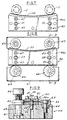
- Each knife blade 33, 34 is in the form of a flat blade clamped in knife blade holder 40 which is mounted on a linear machine slide 41 (FIGS. 4-6) which is in turn mounted on the machine base 21 such that the linear slide 41 is radial to the rotation of the turret 23 (FIG. 6).
- each set of upper tooling 26 on the turret 23 includes a mandrel 43 with its axis parallel to the axis of rotation of the turret 23.
- Each mandrel 43 is rotated past an arcuate fixed gear 44 as the turret is rotated and a pinion gear 45 on each mandrel 43 meshes with fixed gear 44 to rotate the mandrel.
- a closure C is carried on each mandrel 43 and is brought successively into tangential contact with the blades 33, 34 such that scoring takes place in the side wall or skirt of the closure C to delineate the band.
- the rotation of each closure C preferably is a substantially true rolling motion with each blade.
- Each arcuate blade 33, 34 is designed such that at the desired depth of cut, the blade cutting edge is concentric to the turret center of rotation.
- a blade setting fixture 60 enables the pre-setting of each arcuate blade 33, 34 in the holder 40 such that when transferred to the machine mounting the arcuate blade will be aligned such that both the center of the radius of the arc of the arcuate blade and the midpoint of said arc lies on a radial line from the center of the turret parallel to the linear adjustment of the machine slide on which it is mounted.
- a position can be established whereby the blade arc is concentric to the center of rotation of the turret.
- Each knife blade holder 40 includes knife blade holding plates 46a, 46b between which a knife blade 33 or 34 is clamped by headed screws 47.
- the knife blade has openings through which screws 47 extend.
- the plates 46a, 46b and knife blade holder further include openings 48, 49, 50 for engaging dowels 51 on the dovetail slide 52 on the base 21 of the apparatus (FIGS. 3, 4).
- Each knife blade 33, 34 is adjusted in a fixture 60 in a similar manner.
- the radial depth of scoring of each knife blade can be controlled by rotating a knob 54 on the slide in visual guidance by a visual dial indicator 59.
- This construction comprises a screw 55 on which knob 54 is mounted. Screw 55 is journalled on slide 52 and engages a nut 56 fixed on base 53.
- the blade setting fixture 60 includes a base 61, a pair of pilot holes 62 for the mounting of fixed cylindrical stops 63 in the form of rolls and a pair of cam shafts 64 supporting eccentric cams 65 connected to the shafts 64 by torque limiter knobs 66.
- the fixture includes a diamond shaped dowel 57 and a regular dowel 58 (to allow for pitch error) and securing screws (not shown) so as to replicate the machine mounting of the knife holder 40 on the base 61.
- the fixed stops 63 are machined to preset dimensions for each particular blade profile/cap diameter combination, and selected and fitted accordingly.
- a blade is secured snugly but free to move within the holding plates 46a, 46b and the assembly is mounted onto the setting fixture 60.
- the adjustment knobs 66 By carefully rotating the adjustment knobs 66, the blade is moved toward the fixed stops 63 until the blade cutting edge contacts the stops 63.
- the torque limiter knobs 66 slip, the final blade position is reached and the blade can be finally clamped between the holder plates 46a, 46b, by tightening screw 47.
- the blade arc will change for differing closure diameters, and within a limited range it is possible by geometry to ensure that the fixed stops 63 are designed such that a particular "zero" position of the slide as indicated by the digital indicator on the slide, would be the correct position for the desired depth of cut. For closure diameters outside this range, it may be necessary to establish a different slide position f or which the desired depth of cut would be theoretically correct in order that the blade projection from the blade holder is held to a practical minimum. However, due to variability in the parts, and the need to exactly control the depth of cut to ensure adequate band performance, it may be necessary to marginally deviate from this desired setting.
- the slide 52 provides this adjustment and as mentioned is equipped with a digital indicator 59 to provide accurate feedback on the radial adjustment. The resulting minimal blade arc eccentricity to the turret center of rotation is negligible in practice.
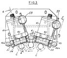
- Cams 70, 71 are provided for lifting and lowering the closure C on the lower tooling 27 into engagement with mandrel 43 by engaging rollers 72, 73, respectively, on the actuator 75 which supports a closure supporting pad 84.
- a cam or roller 77 on the tooling support 79 extends into a slot 78 on the turret 23 to guide the vertical movement of pad 84 (FIGS. 2, 10-12).
- each actuator 75 comprises a block 80 fixed on a shaft 81 slidable in upper and lower linear ball bearings 82, 83 and with antirotation means comprising the roller 77 on the block 80 operating in slot 78 on the turret 23.
- Block 80 supports spring loaded closure support pad 84.
- there is provided a large length to diameter ratio in bearings 82, 83 thereby providing improved lateral support to the closure support pad 84 and maintaining a compact configuration in the vertical axis.
- the tooling 27 is more readily accessible for changing the tooling.
Abstract
Description
- FIG. 1
- is a fragmentary plan view of a rotary scoring apparatus embodying the invention.
- FIG. 2
- is a sectional view taken along the line 2-2 in FIG. 1, parts being broken away.
- FIG. 3
- is a fragmentary partly diagrammatic plan view of a portion of the apparatus shown in FIG. 1.
- FIG. 4
- is a fragmentary part sectional elevational view of a portion of the apparatus taken along the line 4-4 in FIG. 3.
- FIG. 5
- is a fragmentary elevational view taken along the line 5-5 in FIG. 3.
- FIG. 6
- is a fragmentary sectional view taken along the line 6-6 in FIG. 3.
- FIG. 7
- is a partly diagrammatic plan view showing one of the knife blades having an interrupted cutting edge mounted on the apparatus.
- FIG. 8
- is a plan view of a setting fixture with the knife blade shown in FIG. 7 mounted thereon.
- FIG. 9
- is a sectional view taken along the line 9-9 in FIG. 8.
- FIG.10
- is a partly diagrammatic view of the apparatus cams utilized in the rotary apparatus for moving the closures into each of the knife blades and raising and lowering the tooling as the apparatus rotates.
- FIG.11
- is a fragmentary elevational view of a portion of the cams on the apparatus.
- FIG.12
- is a fragmentary plan view of a portion of the apparatus.
Claims (10)
- An apparatus for forming a circumferential score in a plastic closure (C) having a base wall and a peripheral skirt, comprising:a stationary apparatus part (21) which includes at least one knife blade (33, 34) anda rotary apparatus part (20) in which the closure (C) is moved in an arc about a center of rotation of the rotary apparatus past the knife blade (33, 34) to form a circumferential score in the closure skirt, said rotary apparatus part (20) including:a turret (23) rotatable with respect to the knife blade (33, 34) about a vertical axis that forms said center of rotation,a plurality of tooling sets (26, 27) mounted on said turret (23),each tooling set (26, 27) including a mandrel (43) and a support pad (84) on which a closure (C) is supported,each said mandrel (43) being aligned with a support pad (84) and having a vertical axis,a rigid vertical shaft (81) disposed adjacent to each said tooling set (26, 27) and having an axis,a block (80) fixed to each said shaft (81) and supporting the support pad (84) of the adjacent tooling set (26, 27) vertically spaced upper and lower linear bearings (82, 83) mounted on said turret (23) and supporting each said vertical shaft (81) for vertical sliding movement, the axis of said vertical shaft being radially disposed inwardly of the axis of its mandrel (43) and anti-rotation means (77, 78) between each said block (80) and said turret (23) for guiding said vertical movement of each said vertical shaft (81) and each said block (80),and for preventing rotation off each said vertical shaft (81) and each said block (80) about said vertical axis of said vertical shaft (81) relative to the turret (23).
- The apparatus set forth in claim 1
wherein said spaced linear bearings (82, 83) are mounted on said turret (23) such that each block (80) fixed on each said shaft (81) is positioned so that each block (80) is substantially between each said upper bearing (82) and each said lower bearing (83). - The apparatus set forth in claim 1 or 2
wherein each said anti-rotation means (77, 78) comprises a cam means (77) on each said block (80) and a vertically extending slot (78) on said turret (23) into which said cam means extends. - The apparatus set forth in any of claims 1 to 3
wherein said mandrel (43) of said upper tooling (26) is rotatably mounted on a block fixed to said turret (23) and carries a gear (45) which meshes with a stationary gear (44) having an axis coincident with the center of rotation of the turret (23). - The apparatus set forth in claim 4
wherein said support pad (84) is rotatably mounted on said shaft fixed block (80) so as to be driven by said mandrel (43) when there is engagement of the mandrel with the closure (C) supported by said pad (84). - The apparatus set forth in any of claims 1 to 5
wherein said knife blade (33, 34) has at least an arcuate concave cutting edge designed for being concentric to the center of rotation,
wherein a knife holder (40) having clamping means (46a, 46b) for loosening and clamping the knife blades to hold the knife blades stationary during scoring off the closure (C),the knife holder (40) having first locating means (50) engageable with second locating means (51) of said stationary apparatus part (21) so that the knife holder (40) together with the knife blades (33, 34) can be removed from, and refitted onto the stationary apparatus part (21), and
wherein a remote fixture (60) having third locating means (57, 58), is provided for receiving said knife holder (40) together with the knife blades (33, 34) when removed from the stationary apparatus part (21),the fixture (60) has stop means (63) defining an arc for engagement with the arcuate cutting edge of the knife blades (33, 34), and shifting means (64, 65, 66) for moving the knife blades (33, 34) relative to the knife holder (40) and against the stop means (63) with a predetermined force, said stop means comprises spaced stops such that when the arcuate edge of said knife blade dengages said stops, it is positioned such that the arc of the knife blade is at the predetermined position relative to the holder,the clamping means (46a, 46b) of the knife holder (40) are adapted to be tightened to fix the position of the knife relative to the knife holder as adjusted by the fixture (60), and the knife holder (40), together with the knife blades (33, 34) fixed therein, by virtue of its first locating means (50) fits to said second locating means (51) of the stationary apparatus part (21) with the center of the radius off the arc of the knife blades substantially corresponding with the center of rotation of the rotary turret (23). - The apparatus set forth in claim 6
wherein said first, second and third locting means comprise dowels (51, 57, 58) and openings (50) which are complementarily shaped and mate with one another. - The apparatus set forth in claim 6 or 7
wherein said means for moving said knife (33, 34) against stop means (63) comprises rotatable spaced eccentric cams (65) which can be rotating to move the knife against said stop means (63). - The apparatus set forth in claim 8
including force limiting means (66) associated with said rotatable cams (65). - The apparatus sets forth in any one of claims 6 through 9 wherein said stationary apparatus part (21) includes successive slides (41), each supporting a successive knife holder (40) with a successive blade (33, 34).
Applications Claiming Priority (3)
| Application Number | Priority Date | Filing Date | Title |
|---|---|---|---|
| US135830 | 1993-10-14 | ||
| US08/135,830 US5522293A (en) | 1993-10-14 | 1993-10-14 | Method and apparatus for accurately positioning a knife blade for scoring plastic tamper indicating closures |
| EP94115819A EP0657256B1 (en) | 1993-10-14 | 1994-10-07 | Apparatus for scoring plastic tamper indicating closures and method for preparing the apparatus |
Related Parent Applications (1)
| Application Number | Title | Priority Date | Filing Date |
|---|---|---|---|
| EP94115819.8 Division | 1994-10-07 |
Publications (1)
| Publication Number | Publication Date |
|---|---|
| EP0960700A1 true EP0960700A1 (en) | 1999-12-01 |
Family
ID=22469902
Family Applications (2)
| Application Number | Title | Priority Date | Filing Date |
|---|---|---|---|
| EP99116034A Withdrawn EP0960700A1 (en) | 1993-10-14 | 1994-10-07 | Apparatus for forming a circumferential score in a plastic closure |
| EP94115819A Expired - Lifetime EP0657256B1 (en) | 1993-10-14 | 1994-10-07 | Apparatus for scoring plastic tamper indicating closures and method for preparing the apparatus |
Family Applications After (1)
| Application Number | Title | Priority Date | Filing Date |
|---|---|---|---|
| EP94115819A Expired - Lifetime EP0657256B1 (en) | 1993-10-14 | 1994-10-07 | Apparatus for scoring plastic tamper indicating closures and method for preparing the apparatus |
Country Status (14)
| Country | Link |
|---|---|
| US (2) | US5522293A (en) |
| EP (2) | EP0960700A1 (en) |
| JP (1) | JPH07115430B2 (en) |
| AT (1) | ATE200241T1 (en) |
| AU (1) | AU675735B2 (en) |
| BR (1) | BR9404078A (en) |
| CA (1) | CA2123386A1 (en) |
| CO (1) | CO4340635A1 (en) |
| DE (1) | DE69427016T2 (en) |
| DK (1) | DK0657256T3 (en) |
| ES (1) | ES2155458T3 (en) |
| GR (1) | GR3036111T3 (en) |
| PT (1) | PT657256E (en) |
| ZA (1) | ZA948088B (en) |
Families Citing this family (21)
| Publication number | Priority date | Publication date | Assignee | Title |
|---|---|---|---|---|
| US5522293A (en) * | 1993-10-14 | 1996-06-04 | Owens-Illinois Closure Inc. | Method and apparatus for accurately positioning a knife blade for scoring plastic tamper indicating closures |
| DE19758040C2 (en) * | 1997-12-29 | 2001-08-23 | Alcoa Gmbh Verpackwerke | Cutting device for a plastic closure |
| US6119883A (en) * | 1998-12-07 | 2000-09-19 | Owens-Illinois Closure Inc. | Tamper-indicating closure and method of manufacture |
| US6382443B1 (en) | 1999-04-28 | 2002-05-07 | Owens-Illinois Closure Inc. | Tamper-indicating closure with lugs on a stop flange for spacing the flange from the finish of a container |
| US6152316A (en) * | 1999-05-17 | 2000-11-28 | Owens-Illinois Closure Inc. | Tamper-indicating closure and method of manufacture |
| JP4640747B2 (en) * | 2001-06-28 | 2011-03-02 | 日本クラウンコルク株式会社 | Method for forming container lid having tamper evident characteristics |
| US6826994B1 (en) * | 2002-12-20 | 2004-12-07 | Chi-Ti Liao | Breaking-line cutting machine for the twist-off bottle cap |
| US20040187523A1 (en) * | 2003-03-24 | 2004-09-30 | Corning Incorporated | Score bar instrumented with a force sensor |
| ITMO20030177A1 (en) | 2003-06-19 | 2004-12-20 | Sacmi | APPARATUS FOR THE PRODUCTION OF CAPSULES |
| US20080092369A1 (en) * | 2006-09-22 | 2008-04-24 | Chi-Ti Liao | Combination of two machines for making a cap of containers |
| CN101745936B (en) * | 2009-12-28 | 2012-03-07 | 浙江华岳包装机械有限公司 | Cutting labor-saving cutting knife device |
| CN102756406B (en) * | 2011-04-29 | 2016-09-07 | 瓦尔特·纳尔迪 | The operational approach aligned for sawtooth blade |
| US9227335B2 (en) | 2013-12-03 | 2016-01-05 | Axon Llc | System and method for cutting tubular shrink sleeve material for application to containers |
| TWI589498B (en) * | 2015-04-02 | 2017-07-01 | 邁可約瑟夫 麥奎爾 | Cap used for container |
| CN105818206B (en) * | 2016-05-25 | 2017-10-31 | 沈玉琼 | A kind of plastic circular tank body clamping device |
| CN111229557B (en) * | 2019-03-19 | 2021-04-09 | 义乌市易开盖实业公司 | Scraping and blanking device and method for twist cover |
| CN112297112A (en) * | 2019-07-30 | 2021-02-02 | 苏州腾达光学科技有限公司 | OCA colloid is with dividing roller of cutting of strip machine |
| CN110450435B (en) * | 2019-08-16 | 2020-09-04 | 浙江庆丰绝热科技股份有限公司 | Polyurethane insulation board forming processing method |
| EP3831557A1 (en) * | 2019-12-05 | 2021-06-09 | PackSys Global AG | Device and method for producing a cutting geometry in a closure cap for a container |
| CN112720964A (en) * | 2021-01-16 | 2021-04-30 | 安徽金田加贝智能设备有限公司 | Automatic edge trimmer for plastic products |
| IT202100007262A1 (en) * | 2021-03-25 | 2022-09-25 | Sacmi | CUTTING DEVICE FOR CUTTING CAPSULES |
Citations (9)
| Publication number | Priority date | Publication date | Assignee | Title |
|---|---|---|---|---|
| US1943107A (en) * | 1931-06-11 | 1934-01-09 | Waterbury Farrel Foundry & Mac | Vertical automatic shell-trimming machine |
| US3210979A (en) * | 1962-05-03 | 1965-10-12 | Thelma E Laxo | Can beading and parting machine |
| US3481232A (en) * | 1967-10-23 | 1969-12-02 | Chemetron Corp | Method and apparatus for making nonpilferable container closures |
| DE1930043A1 (en) * | 1969-06-13 | 1970-12-17 | Schuler Gmbh L | Device for beading, knurling, boerdeln, trimming or similar processing of sleeves or the like. Workpieces |
| US3994613A (en) * | 1975-03-26 | 1976-11-30 | Cedar Rapids Engineering Company | Device for positioning cutters in an annular cutter holder |
| CA1161611A (en) | 1982-03-29 | 1984-02-07 | Hamelin Inc. | Process and apparatus for production of bottle caps with tear strips |
| EP0236004A1 (en) * | 1986-02-18 | 1987-09-09 | Adolph Coors Company | Apparatus and method for trimming a can body |
| US5090788A (en) | 1989-07-27 | 1992-02-25 | Owens-Illinois Closure Inc. | Tamper indicating package |
| EP0621475A1 (en) | 1993-04-19 | 1994-10-26 | Owens-Brockway Glass Container Inc. | Apparatus for inspecting containers with a rotating inspection head |
Family Cites Families (26)
| Publication number | Priority date | Publication date | Assignee | Title |
|---|---|---|---|---|
| CA399618A (en) * | 1941-09-30 | Pasquale Colio William | Coating composition | |
| US2507427A (en) * | 1946-07-11 | 1950-05-09 | West Co | Container-sealing machine |
| US2745135A (en) * | 1950-09-29 | 1956-05-15 | Anchor Hocking Glass Corp | Molding machine |
| US2952035A (en) * | 1953-10-16 | 1960-09-13 | Anchor Hocking Glass Corp | Apparatus for applying gaskets to closure caps |
| US2952036A (en) * | 1955-01-04 | 1960-09-13 | Anchor Hocking Glass Corp | Apparatus for making composite articles |
| US2954585A (en) * | 1955-08-03 | 1960-10-04 | Continental Can Co | Crown cap lining machine |
| US2877493A (en) * | 1956-01-04 | 1959-03-17 | Anchor Hocking Glass Corp | Device for molding gaskets |
| US3481233A (en) * | 1966-08-22 | 1969-12-02 | Chemetron Corp | Method and apparatus for removing the outer surface of an embossment of a cylindrical skirt of a cap |
| US3600816A (en) * | 1968-04-05 | 1971-08-24 | Towa Electric | Rotary cutter blade-adjusting apparatus |
| US3577595A (en) * | 1968-08-26 | 1971-05-04 | Zapata Industries Inc | Rotatable crown-filling machine and method for applying sealing rings of plastic to the periphery of the crown interior |
| US3606550A (en) * | 1969-04-21 | 1971-09-20 | Everede Tool Co | Method and apparatus for setting the position of a bore cutting tool |
| US3867763A (en) * | 1969-07-07 | 1975-02-25 | Wickman Mach Tool Sales Ltd | Setting fixture for machine tools |
| DE2035467C3 (en) * | 1969-07-29 | 1979-06-13 | Ettore Imola Busi (Italien) | Device for forming inner linings made of thermoplastic in sealing capsules or the like |
| US3988953A (en) * | 1975-04-21 | 1976-11-02 | J. R. Simplot Company | Method and apparatus for treating vegetable segments |
| CH593111A5 (en) * | 1975-05-26 | 1977-11-30 | Oertli Werkzeuge Ag | |
| US4014228A (en) * | 1975-09-10 | 1977-03-29 | Ball Corporation | Method and apparatus for trimming cylindrical articles |
| US4322009A (en) * | 1980-05-19 | 1982-03-30 | Owens-Illinois, Inc. | Tamper proof molded plastic closure |
| US4545496A (en) * | 1981-07-24 | 1985-10-08 | H-C Industries, Inc. | Plastic closure with mechanical pilfer band |
| JPS5818231A (en) * | 1981-07-28 | 1983-02-02 | Q P Corp | Method of removing sealed opening part of synthetic resin container |
| US4613052A (en) * | 1985-04-29 | 1986-09-23 | Owens-Illinois, Inc. | Tamper-indicating closure, container and combination thereof |
| US4721218A (en) * | 1987-02-17 | 1988-01-26 | Owens-Illinois Closure Inc. | Tamper indicating package |
| US4801031A (en) * | 1987-05-28 | 1989-01-31 | Owens-Illinois Closure Inc. | Tamper-indicating closures and packages |
| DE4013289C2 (en) * | 1990-04-26 | 1998-10-15 | Kolbus Gmbh & Co Kg | Setting gauge for the knives of a three-knife cutting machine |
| US5488888A (en) * | 1993-04-19 | 1996-02-06 | Owens-Illinois Closure Inc. | Method of forming bridges in tamper indicating closures |
| US5522293A (en) * | 1993-10-14 | 1996-06-04 | Owens-Illinois Closure Inc. | Method and apparatus for accurately positioning a knife blade for scoring plastic tamper indicating closures |
| US5557999A (en) * | 1994-01-14 | 1996-09-24 | H-C Industries, Inc. | Method for manufacturing a tamper-indicating plastic closure |
-
1993
- 1993-10-14 US US08/135,830 patent/US5522293A/en not_active Expired - Lifetime
-
1994
- 1994-04-14 ZA ZA948088A patent/ZA948088B/en unknown
- 1994-05-11 CA CA002123386A patent/CA2123386A1/en not_active Abandoned
- 1994-10-07 AU AU74495/94A patent/AU675735B2/en not_active Ceased
- 1994-10-07 ES ES94115819T patent/ES2155458T3/en not_active Expired - Lifetime
- 1994-10-07 DE DE69427016T patent/DE69427016T2/en not_active Expired - Fee Related
- 1994-10-07 PT PT94115819T patent/PT657256E/en unknown
- 1994-10-07 DK DK94115819T patent/DK0657256T3/en active
- 1994-10-07 EP EP99116034A patent/EP0960700A1/en not_active Withdrawn
- 1994-10-07 EP EP94115819A patent/EP0657256B1/en not_active Expired - Lifetime
- 1994-10-07 AT AT94115819T patent/ATE200241T1/en not_active IP Right Cessation
- 1994-10-12 CO CO94046768A patent/CO4340635A1/en unknown
- 1994-10-13 BR BR9404078A patent/BR9404078A/en not_active IP Right Cessation
- 1994-10-14 JP JP6275591A patent/JPH07115430B2/en not_active Expired - Lifetime
-
1997
- 1997-09-29 US US08/939,857 patent/US5916342A/en not_active Expired - Lifetime
-
2001
- 2001-06-22 GR GR20010400961T patent/GR3036111T3/en not_active IP Right Cessation
Patent Citations (9)
| Publication number | Priority date | Publication date | Assignee | Title |
|---|---|---|---|---|
| US1943107A (en) * | 1931-06-11 | 1934-01-09 | Waterbury Farrel Foundry & Mac | Vertical automatic shell-trimming machine |
| US3210979A (en) * | 1962-05-03 | 1965-10-12 | Thelma E Laxo | Can beading and parting machine |
| US3481232A (en) * | 1967-10-23 | 1969-12-02 | Chemetron Corp | Method and apparatus for making nonpilferable container closures |
| DE1930043A1 (en) * | 1969-06-13 | 1970-12-17 | Schuler Gmbh L | Device for beading, knurling, boerdeln, trimming or similar processing of sleeves or the like. Workpieces |
| US3994613A (en) * | 1975-03-26 | 1976-11-30 | Cedar Rapids Engineering Company | Device for positioning cutters in an annular cutter holder |
| CA1161611A (en) | 1982-03-29 | 1984-02-07 | Hamelin Inc. | Process and apparatus for production of bottle caps with tear strips |
| EP0236004A1 (en) * | 1986-02-18 | 1987-09-09 | Adolph Coors Company | Apparatus and method for trimming a can body |
| US5090788A (en) | 1989-07-27 | 1992-02-25 | Owens-Illinois Closure Inc. | Tamper indicating package |
| EP0621475A1 (en) | 1993-04-19 | 1994-10-26 | Owens-Brockway Glass Container Inc. | Apparatus for inspecting containers with a rotating inspection head |
Also Published As
| Publication number | Publication date |
|---|---|
| EP0657256A2 (en) | 1995-06-14 |
| ES2155458T3 (en) | 2001-05-16 |
| CO4340635A1 (en) | 1996-07-30 |
| DK0657256T3 (en) | 2001-06-18 |
| AU675735B2 (en) | 1997-02-13 |
| GR3036111T3 (en) | 2001-09-28 |
| DE69427016D1 (en) | 2001-05-10 |
| ZA948088B (en) | 1995-06-07 |
| DE69427016T2 (en) | 2001-10-18 |
| US5522293A (en) | 1996-06-04 |
| AU7449594A (en) | 1995-05-04 |
| US5916342A (en) | 1999-06-29 |
| JPH07178851A (en) | 1995-07-18 |
| JPH07115430B2 (en) | 1995-12-13 |
| ATE200241T1 (en) | 2001-04-15 |
| EP0657256B1 (en) | 2001-04-04 |
| PT657256E (en) | 2001-08-30 |
| CA2123386A1 (en) | 1995-04-15 |
| EP0657256A3 (en) | 1995-09-06 |
| BR9404078A (en) | 1995-06-13 |
Similar Documents
| Publication | Publication Date | Title |
|---|---|---|
| EP0960700A1 (en) | Apparatus for forming a circumferential score in a plastic closure | |
| EP0312703B1 (en) | Cutting apparatus | |
| US5564319A (en) | Apparatus for forming bridges in tamper indicating closures | |
| EP0486533B1 (en) | Apparatus for edge notching a continuously moving web | |
| US5816029A (en) | Anti-rotation device for capping machine | |
| US5111635A (en) | Arrangement for closing bottles | |
| JPH07164382A (en) | Device for cutting groove in corrugated and twin wall pipe | |
| US4857349A (en) | Apparatus for rolling circular dough product | |
| US4534684A (en) | Apparatus for milling a gear for a double enveloping worm gear drive | |
| US7059232B2 (en) | Method of forming bridges in tamper-indicating closures | |
| US4962684A (en) | Cutting device for a board machine | |
| US5244321A (en) | Key cutting apparatus | |
| US4580492A (en) | Product code wheel assembly | |
| CA1264461A (en) | Machine for labeling containers around their complete circumference | |
| US4288680A (en) | Apparatus for cutting mould notches for strip steel cutting tools | |
| US5150594A (en) | Machine for beading cylindrical cans or can bodies | |
| US4266329A (en) | Apparatus for positioning out-of-round workpieces particularly piston rings | |
| US5636958A (en) | Slitter for tamper-evident closures | |
| US6171032B1 (en) | Mechanically actuated chip-less boring head for forming a hole in a workpiece | |
| JPH0223313B2 (en) | ||
| US20040238330A1 (en) | Adjustable sorter disc method apparatus and system | |
| US4411567A (en) | Tubular key cutting machine | |
| CN217210823U (en) | Roller-passing measuring and coding jig | |
| JPH0260460B2 (en) | ||
| CN116783046A (en) | Cutting device and method for cutting caps |
Legal Events
| Date | Code | Title | Description |
|---|---|---|---|
| PUAI | Public reference made under article 153(3) epc to a published international application that has entered the european phase |
Free format text: ORIGINAL CODE: 0009012 |
|
| 17P | Request for examination filed |
Effective date: 19990907 |
|
| AC | Divisional application: reference to earlier application |
Ref document number: 657256 Country of ref document: EP |
|
| AK | Designated contracting states |
Kind code of ref document: A1 Designated state(s): AT BE CH DE DK ES FR GB GR IE IT LI LU MC NL PT SE |
|
| AX | Request for extension of the european patent |
Free format text: LT;SI |
|
| AKX | Designation fees paid |
Free format text: AT BE CH DE DK ES FR GB GR IE IT LI LU MC NL PT SE |
|
| GRAG | Despatch of communication of intention to grant |
Free format text: ORIGINAL CODE: EPIDOS AGRA |
|
| GRAG | Despatch of communication of intention to grant |
Free format text: ORIGINAL CODE: EPIDOS AGRA |
|
| GRAH | Despatch of communication of intention to grant a patent |
Free format text: ORIGINAL CODE: EPIDOS IGRA |
|
| 17Q | First examination report despatched |
Effective date: 20010420 |
|
| STAA | Information on the status of an ep patent application or granted ep patent |
Free format text: STATUS: THE APPLICATION IS DEEMED TO BE WITHDRAWN |
|
| 18D | Application deemed to be withdrawn |
Effective date: 20010916 |