EP0960695B1 - Hammer-type stapler - Google Patents
Hammer-type stapler Download PDFInfo
- Publication number
- EP0960695B1 EP0960695B1 EP99303971A EP99303971A EP0960695B1 EP 0960695 B1 EP0960695 B1 EP 0960695B1 EP 99303971 A EP99303971 A EP 99303971A EP 99303971 A EP99303971 A EP 99303971A EP 0960695 B1 EP0960695 B1 EP 0960695B1
- Authority
- EP
- European Patent Office
- Prior art keywords
- staple
- drive
- drive track
- driving element
- track
- Prior art date
- Legal status (The legal status is an assumption and is not a legal conclusion. Google has not performed a legal analysis and makes no representation as to the accuracy of the status listed.)
- Expired - Lifetime
Links
- 230000003116 impacting effect Effects 0.000 claims description 9
- 230000007246 mechanism Effects 0.000 claims description 9
- 238000000034 method Methods 0.000 claims description 7
- 230000000694 effects Effects 0.000 claims description 6
- 230000009471 action Effects 0.000 claims description 5
- 230000004044 response Effects 0.000 claims description 4
- 230000000717 retained effect Effects 0.000 description 3
- 210000005069 ears Anatomy 0.000 description 2
- 238000003780 insertion Methods 0.000 description 2
- 230000037431 insertion Effects 0.000 description 2
- 230000000149 penetrating effect Effects 0.000 description 2
- 230000006835 compression Effects 0.000 description 1
- 238000007906 compression Methods 0.000 description 1
- 239000013536 elastomeric material Substances 0.000 description 1
- 230000006872 improvement Effects 0.000 description 1
- 230000035939 shock Effects 0.000 description 1
- 238000003466 welding Methods 0.000 description 1
Images


Classifications
-
- B—PERFORMING OPERATIONS; TRANSPORTING
- B25—HAND TOOLS; PORTABLE POWER-DRIVEN TOOLS; MANIPULATORS
- B25C—HAND-HELD NAILING OR STAPLING TOOLS; MANUALLY OPERATED PORTABLE STAPLING TOOLS
- B25C5/00—Manually operated portable stapling tools; Hand-held power-operated stapling tools; Staple feeding devices therefor
- B25C5/10—Driving means
- B25C5/11—Driving means operated by manual or foot power
Definitions
- This application relates to manually operated impact staplers sometimes referred to as hammer-type staplers and to a method of using such a stapler, according to the preambles of independent claims 1 and 19, and 22 respectively.
- a typical hammer-type stapler includes a handle for enabling an operator to manually grasp the stapler and a frame which is fixed to or forms a part of the handle.
- the frame carries the usual staple driving components which include a structure defining a drive track, a staple driving element movable through the drive track and a magazine assembly for guiding a staple stick in the magazine assembly into the drive track so that successive leading staples are driven by the staple driving element through the drive track into the workpiece during the drive stroke of the staple driving element and for biasing a leading staple to move into the drive track during the return stroke of the staple driving element.
- Staplers of the hammer-type which are known fall generally into two categories. Probably the most prevalent is the hammer-type stapler in which the staple driving element is fixed to the frame and handle. In this category, the magazine and staple drive track structure are moved with respect to the driver on impact. Examples of hammer-type staplers of the fixed driver- movable magazine category are exemplified in U.S. Patents 2,664,565, which discloses the preambles of the said independent claims, and 2,667,639. In the other category, the magazine assembly and the drive track structure are fixed with respect to the frame and handle and the staple driving element is moved through the drive track in response to the impact. Examples of hammer-type staplers of this type are illustrated in U.S. Patents 2,325,341 and 2,896,210.
- a hammer-type stapler comprising a frame structure including a hand grip portion constructed and arranged to be manually grasped by an operator.
- a magazine assembly includes structure defining a staple drive track which is mounted for relative movement with respect to the frame structure and structure defining a staple stick feed track leading to the staple drive track.
- a staple driving assembly is provided including a staple driving element mounted for relative movement with respect to the frame structure within the staple drive track through successive cycles each including a drive stroke and a return stroke.
- the magazine assembly includes a loading and feeding mechanism constructed and arranged to facilitate the manual loading of a staple stick into the feed track and to feed a loaded staple stick along the feed track in a feed direction so that successive leading staples are moved into the drive track to be driven therefrom in a drive direction into a workplace during the drive stroke of successive cycles of the driving element.
- the driving element and the drive track structure are constructed and arranged with respect to the frame structure to move through a drive stroke incident to an operator grasping the hand grip portion and manually impacting the drive track structure on a workpiece to arrest the movement of the drive track structure on the workpiece while the frame structure and the staple driving element continue to move toward the workpiece with respect to the arrested drive track structure.
- the staple driving element is constructed and arranged with respect to the frame structure and the drive track structure such that the continued movement of the staple driving element toward the workpiece with respect to the arrested drive track structure is further and faster than the continued movement of the frame structure toward the workpiece with respect to the arrested drive track structure enabling the staple driving element to effect a drive stroke through the drive track and to drive a staple therein into the workpiece while the frame structure is undergoing a relative movement with respect to the drive track structure which is less than substantially equal to the relative movement of the staple driving element with respect to the drive track structure during the drive stroke of the staple driving element.
- a spring system is provided which is constructed and arranged to effect opposite relative movements between the driving element and drive track structure with respect to the frame structure during which the staple driving element is moved within the drive track through a return stroke.
- an improvement in operating characteristics and efficiency is achieved by essentially moving two structures with respect to the frame structure approximately one half the distance of the stroke itself rather than one structure through the entire stroke while the other structure is held stationary.
- the present invention contemplates that the relative motion of the staple-driving element can be accomplished by a movable workpiece striking element separate from the magazine such as disclosed in the '210 patent previously cited. However, it is greatly preferred that this relative motion be accomplished by the magazine itself since, in accordance with the principles of the present invention, the magazine has a relative movement as well.
- the principles of the present invention have applicability to hammer-type staplers in which the feed track is related to the drive track in conventional perpendicular fashion.
- the hammer-type stapler disclosed herein has an overly canted drive track. This feature, which is claimed in my concurrently filed application, is provided to alleviate the knuckle-busting problem and is preferred in combination with the features of the present invention already mentioned.
- the stapler 10 includes an elongated fore and aft extending frame structure, generally indicated at 12, which includes a handle or hand grip portion, generally indicated at 14, at its rearward end portion, the frame structure extending forwardly of the hand grip portion 14.
- a magazine assembly mounted within the frame structure 12 for relative movement with respect thereto is a magazine assembly, generally indicated at 16, which includes structure defining a staple drive track, generally indicated at 18, and structure defining a staple stick feed track, generally indicated at 20, which leads to the drive track 18.
- a staple driving assembly mounted on the frame structure 12 for relative movement with respect thereto is a staple driving assembly, generally indicated at 22, which includes a staple driving element 24 mounted within the drive track 18.
- the magazine assembly 16 also includes a loading and feeding mechanism, generally indicated at 26, which is constructed and arranged to facilitate the manual loading of a staple stick into the drive track and to guide a loaded staple stick along the feed track 20 so that a leading staple is biased to move into the drive track 18.
- a loading and feeding mechanism generally indicated at 26, which is constructed and arranged to facilitate the manual loading of a staple stick into the drive track and to guide a loaded staple stick along the feed track 20 so that a leading staple is biased to move into the drive track 18.
- the driving element 24 and the drive track structure 18 are constructed and arranged with respect to the frame structure 12 to move through a drive stroke incident to an operator grasping the hand grip portion 14 and manually impacting the drive track structure 18 on a workpiece during which drive stroke the total distance of relative movement between the driving element 24 and drive track structure 18 is accomplished by a movement of the driving element 24 with respect to the frame structure 12 a distance less than the total distance and a movement of the drive track structure 18 with respect to the frame structure 12 a distance less than the total distance which, when added to the distance of movement of the driving element 24, is equal to the total distance.
- a spring system is provided which is constructed and arranged to effect a relative movement between the driving element 24 and the drive track structure 18 which respect to the frame structure 12 through a return stroke during which the total distance of relative movement between the driving element 24 and the drive track structure 18 is accomplished by movement of the driving element 24 with respect to the frame structure 12 a distance less than the total distance and a movement of the drive track structure 18 with respect to the frame structure 12 a distance less than the total distance which when added to the distance of movement of the driving element 24 is equal to the total distance.
- the drive track structure 18 and the feed track structure 20 are constructed and arranged so that the direction of guided movement of the staple stick along the feed track 20 is at an angle greater than 90° with respect to the direction of the drive stroke of the driving element 24 within the drive track 18 so that the staple crown enters the drive track 18 while the lower penetrating ends of the staple legs are displaced angularly with respect to the direction of the drive stroke.
- the drive track structure 18 is constructed and arranged to cause the leading staple to be moved into alignment with the drive track 18 during the drive stroke movement so as to be driven into the workpiece in the direction of the drive stroke enabling the hand grip portion 14 to be positioned for manual gripping so that the knuckles are spaced from a flat workplace surface in which a staple has been driven generally perpendicularly therein.
- the frame structure 12 is hollow and elongated in the front-to-rear direction.
- the hollow frame structure 12 is in the form of a frame member 30 which is constructed from two halves fixedly interconnected together, as by a series of fasteners or the like.
- the frame member 30 extends forwardly of the hand grip portion 14. As best shown in Figure 3, this forwardly extending portion is open along a lower extent thereof, as indicated at 34, and along a lower forward extent thereof, as indicated at 36.
- the frame structure 12 also includes a front exterior cover member, generally indicated at 38, which comprises a forward wall 40 disposed in closing relation to the forward opening 36 of the frame member 30 and a pair of rearwardly bent side walls 42 overlapping forward side portions of the frame member 30.
- a front exterior cover member generally indicated at 38, which comprises a forward wall 40 disposed in closing relation to the forward opening 36 of the frame member 30 and a pair of rearwardly bent side walls 42 overlapping forward side portions of the frame member 30.
- Formed integrally at the upper forward edges of the cover side walls 42 are two short top walls 44 which are bent inwardly toward one another to overlie the upper forward portion of the frame member 30.
- the top walls 44 are available to function as a hammering surface for staples which have been driven improperly and must be made flush with the workpiece surface.
- the feed track structure 20 of the magazine assembly 16 is preferably constructed and arranged to accommodate two staple sticks.
- the feed track structure 20 includes an elongated housing member 46 of inverted U-shaped cross-sectional configuration disposed in exterior confining relation to staples loaded in the magazine assembly 16 and an elongated core member 48 mounted for movement between (1) an operating position disposed in interior confining relation to staples loaded in the magazine assembly 16 and (2) a loading position disposed in a position to provide access for the insertion of a staple stick into the housing member 46 through the U-shaped cross-sectional configuration thereof.
- the core member 48 is also of inverted U-shaped cross-sectional configuration and is longitudinally slidably mounted within the housing member 46 so as to extend through and rearwardly of the hollow handle portion when in the loading position thereof.
- the housing member 46 is movably mounted within the frame member 30 so that the forward end swings with respect to the frame member 30 from a normal inoperative position, as shown in Figures 1 and 3, into an upwardly displaced operative position in response to the impacting of the drive track structure 18 with a workpiece.
- the extent of the movement is approximately one-half the distance of the drive stroke of the staple driving element 24 with respect to the drive track structure 18.
- the manner in which the housing member 46 is mounted within the frame member 30 is best shown in Figure 4A.
- the depending legs of the U-shaped cross-section of the housing member includes two laterally spaced rearwardly extending extensions 50 having small spaced barbs extending from the upper and lower edges thereof.
- each extension 50 Extended over each extension 50 is a flat bearing sleeve 52 which is retained in position by the barbs.
- the bearing sleeves 52 fit within laterally spaced receiving surfaces 54 formed in the rearward end of the frame member 30 shaped to allow the bearing sleeves to pivot about a transverse axis in conjunction with a limited amount of longitudinal movement.
- the mounting of the core member 48 with respect to the housing member 46 forms a part of the loading and feeding mechanism 26 of the magazine assembly 16.
- a releasable latch assembly generally indicated at 56.
- the latch assembly 56 basically functions to releasably retain the core member 48 in the operating position thereof.
- it also is constructed and arranged to allow the core member 48 when in its operating position to resiliently yieldingly move rearwardly in response to a staple jam occurrence during a drive stroke.
- the latch assembly 56 includes a latch member 58 having a pivot pin 60 extending laterally through the forward portion thereof.
- the opposite ends of the pivot pin 60 extend outwardly of the latch member 58 and into horizontal slots 62 formed in the legs of the U-shaped core member 48.
- the latch member 58 includes a forwardly opening bore below the pivot pin 60 which receives the rear end portion of a compression coil spring 64, the forward end of which bears against tab structure struck and bent from the core member 48.
- the spring 64 thus serves to resiliently bias the core member 48 forwardly into its operating position and the latch member 58 rearwardly.
- the rearward spring bias of the latch member 58 is resisted by the engagement of an upwardly and rearwardly disposed latch member catch 66 against an edge 68 defining an opening in the top wall of the housing member 46 and by the engagement of lateral stop portions 70 (see Figure 10) of the latch member 58 upwardly against the downwardly facing free edges of the legs of the core member 48.
- the latch member 58 includes a rear digital engaging portion 72 which can be digitally engaged and moved downwardly to release the latch member 58 by a clockwise pivotal action, as viewed in Figure 4, to allow the core member 48 to be moved rearwardly from its operating position to its loading position.
- the coil spring 74 extends forwardly and is trained about a grooved roller 76 rotatably carried by a core tip 78 fixed to the forward end of the core member 48.
- the coil spring 74 extends rearwardly from the roller 76 and has its opposite end fixed to a pusher 80 riding within a central longitudinal slot in the top wall of the core member 48 and within the staple space defined by the housing member 46 and core member 48.
- the spring 74, roller 76 and pusher 80 form a part of the loading and feeding mechanism 26 of the magazine assembly 16.
- the core tip 78 forms a part of the drive track structure 18.
- the core tip 78 includes a forwardly facing planar surface 82 which defines the lower central rearward portion of the drive track 18.
- the upper edge of the surface 82 constitutes a cut-off edge for the magazine beyond which the crown of the leading fastener extends when moved into the drive track.
- the edge and the upper surface of the core tip 78 extending rearwardly thereof support the staple next to the leading staple to facilitate cut-off from the staple stick during the drive stroke.
- the surface 82, as well as the drive track 18 itself, rather than being at right angles to the feed track 20 is at a slightly greater angle, as, for example, approximately 97°, so that when the crown of the leading staple moves from the feed track to the drive track, the penetrating free ends of the staple legs are displaced rearwardly from the surface 82.
- Extending laterally outwardly from opposite sides of the lower end of the surface 82 are integral portions which define two spaced forwardly and downwardly slanted cam surfaces 84 leading to the surface 82 at their lower end.
- the cam surfaces 84 extend downwardly in flush relation with the surface 82 to form spaced forwardly facing stop surfaces 85.
- the lower ends of the legs of the inverted U-shaped housing member 46 are offset laterally outwardly in order to slidably accommodate the integral core tip portions which define the cam surfaces 84.
- the cam surfaces 84 are in a position to be engaged by the free ends of the legs of a staple being driven in the event that it has not been aligned with the canted drive track 18 as it reaches the level of the surfaces 84.
- the drive track structure 18 also includes a track member which includes a front wall 86, having parallel side walls 88 extending rearwardly therefrom. The portion of the side walls 88 which are coextensive with the housing member 46 are fixed, as by welding or the like, to the housing member 46. Fixed to the lower end of the track member and housing member 46 is a plate 89 which provides a workpiece striking surface for the fixedly interconnected drive track structure 18 and feed track structure 20.
- the lower rearward portion of the side walls 88 are lanced laterally outwardly along a cut 87.
- the rearwardly facing edge of which provide surfaces which are engaged by the stop surfaces 85 of the core tip 78 under the bias of spring 64.
- a shock absorbing pad 90 is mounted on the top wall of the housing member 46.
- the pad 90 includes a pair of laterally outwardly extending flange portions 92 which are engaged by the lower edges of the side walls 88 to retain the pad 90 in position.
- Extending between the side walls 88 forwardly of the pad 90 is a pin 94 the forward surface of which defines the rear surface of the drive track above the housing member 46.
- the opposite ends of the pin 94 extend outwardly of the side walls 88 and pivotally receive the legs of a U-shaped spring member 96.
- the spring member 96 includes a front in-turned upper portion 98 which serves to bias the spring member 96 to pivot about the pin 94.
- the lower rear surface of the U-shaped spring member engages a ball 100 disposed within an opening 102 formed in the front track member wall 86.
- the opening 102 is shaped to allow the ball 100 to protrude rearwardly into the drive track at a position which is centrally located just below the crown of a leading staple fed from the feed track into the drive track.
- the ball 100 is engaged by the staple crown just after the staple is stripped from its stick and this engagement facilitates alignment of the angular engagement of the end of the staple driving element 24 with the upper surface of the staple crown which aligns the staple legs with the overly angled drive track.
- the staple driving assembly 22 includes a motion-transmitting mechanism in the form of a lever 104 pivoted to the frame member 30 and interconnected between the housing member 46 and the staple driving element 24.
- the lever 104 is pivoted intermediate its ends by a pivot pin 106 in the form of a flat-headed bolt with an internally threaded bore in its shank.
- the pivot pin 106 extends within a pair of resilient bushings 108 disposed on opposite sides of the lever 104.
- Bushings 108 are seated within in-turned opposed opening-defining annular flanges 110 formed in the frame member 30.
- the side walls 42 of the cover member are also apertured and countersunk to allow the pin 106 to extend therethrough in a position to receive the flat head in one side wall 42.
- a smaller flat head bolt 112 is threaded within the threaded shank bore of the pin 106 to complete the pivotal mounting of the lever which by virtue of the resiliency of the bushings 108 is allowed to have a limited amount of transverse movement.
- Bushings 108 are preferably formed of a suitable rubber but they may be plastic or other elastomeric material.
- the rearward end of the lever 104 is pivotally connected with the housing member 46 by a pivot pin 114 which extends through the lever 104 and has its ends fixed to the legs of a U-shaped bracket 116 fixed to the upper wall of the housing member 46.
- the forward end of the lever 104 includes a protusion 118 which extends within an opening 120 formed in the upper end of the staple driving element 24.
- the spring system 28 is in the form of a flat leaf spring 122 having a front end engaged with the rear end of the lever 104.
- a mid-portion of the flat leaf spring 122 is disposed in flexed engagement with an interior downwardly facing surface of the frame member 30 just forwardly of the forward end of the hand grip portion 14.
- the rear of the flat leaf spring includes two integral downwardly turned ears 124 spaced apart so as to embrace the legs of the U-shaped housing member 46.
- the ears 124 have downwardly opening recesses 126 therein to receive two tabs 128 cut and bent outwardly from the legs of the housing member 46 to retain the spring 122 in operating position.
- the operator simply grips the hand portion 14 and swings the stapler 10 in a hammer-like movement into the workpiece where the staple is to be driven.
- the staple drive track structure 18 and feed track structure 20 will have its movement arrested while the frame member 30 continues to move in a direction toward the workpiece.
- This relative movement of the housing member 46 with respect to the frame member 30 causes the pivot pin 114 to move upwardly which, in turn, effects a downward movement of the forward end of the lever 104 which carries with it the staple driving element 24.
- the staple driving element 24 is simultaneously moved with respect to the housing member 30 with the staple drive track structure 18 and feed track structure 20.
- the lower end thereof will initially engage the crown of the leading staple fed from the feed track into the drive track. Since the upper surface of the crown is at an angle with respect to the lower surface of the staple driving element 24, the interengagement therebetween will tend to both strip the leading fastener from the stick within the feed track and to move the lower end of the legs forwardly toward alignment with the drive track. Immediately after the staple is stripped, the forward lower surface of the staple crown will engage the ball 100 and this engagement, in turn, will tend to align the legs of the staple with the drive track.
- the ball 100 moves within the opening 102 against the bias of the spring member 96 where it is retained by the presence of the staple driving element 24 during the remainder of the drive stroke and the subsequent portion of the return stroke until the end moves above the ball 100.
- the free ends of the legs will engage the cam surfaces 84 and, as the driving movement of the staple continues, the staple will be fully aligned with the drive track so as to enter the workpiece in a perpendicular relationship.
- the hand grip portion 14 is spaced from a flat workpiece which has been engaged by the plate 89 and had a staple driven perpendicularly therein. This relationship practically eliminates the problem of the operator's knuckles striking the workpiece in normal operation on floors and roofs.
- the leaf spring 122 is stressed by virtue of the upward movement of the rear end of the lever 104 so that as soon as the drive stroke is completed, the spring 122 will serve to return the staple drive track structure 18 and feed track structure 20 as well as the staple driving element 24 back into the inoperative positions thereof, as shown in Figure 3.
- the staples disposed within the feed track are resiliently urged in a forward direction to move the leading staple of the stick into the drive track by virtue of the pusher 80 biased by the spring 74.
- the leading staple will then be biased into the drive track to complete the cycle and condition the stapler for another driving action.
- the core member 48 and the surface 82 of the core tip 78 which is fixed thereto can move rearwardly by virtue of the interconnection of the core member 48 with the latch assembly 56.
- the core member 48 is capable of being moved resiliently rearwardly against the action of spring 64 since the latch member 58 is retained in the position shown in Figure 4 against rearward movement by virtue of the engagement of the catch 66 with the surface 68 and the flanges 70 with the undersides of the legs of the core member 48 as shown in Figure 10.
- the core member 48 can move rearwardly by virtue of the elongated slot 62 which receives the pin 60 and is biased forwardly by the spring 64, a yielding rearward movement of the core tip 78 and core member 48 can take place in the event of a staple jam.
- the latch member 58 is digitally engaged at the rear portion 72 so as to pivot the latch member 58 from the core member retaining position shown in Figure 4 in a clockwise direction into a core member releasing position, wherein the catch 66 extends below the opening 68, thus allowing the entire core to slide rearwardly and exposing the interior of the housing member 46 through the opening 34.
- the supply of staples can be replenished by simply dropping a staple stick into the housing member 46 in an inverted relation with the crowns of the stick downwardly.
- the arrangement is such that a first stick can be moved into the housing member 46 and then moved rearwardly in order to provide space for the insertion of a second stick.
- the core member 48 is moved forwardly and during the end of this movement, which is determined by the engagement of forwardly facing stop surfaces 85 with the rearwardly facing edges of cuts 87, the latch member 56 will be cammed by the forward surface of the catch 66 from its core retaining position into its core releasing position and then returned by the action of the spring 64 into its core retaining position to enable the stapler to again be used to drive staples.
- a stapler preferably a hammer-type stapler, comprising a frame structure including a hand grip portion; a magazine assembly including a staple drive track and a staple feed track leading to said staple drive track; and a staple driving element mounted for movement along said staple drive track through successive cycles each including a drive stroke and a return stroke; said driving element being arranged to move through a drive stroke upon an operator grasping said hand grip portion and manually impacting the drive track on a workpiece to arrest the movement of the drive track on the workpiece while said staple driving element continues to move toward said workpiece with respect to the arrested drive track; and means for producing during a drive stroke movement of the driving element along the drive track by combined movement of both the driving element relative to the frame structure and of the drive track relative to the frame structure.
- said staple feed track is coupled to said staple drive track to move therewith during a drive stroke
- said motion producing means is coupled between said feed track, said frame structure, and said staple driving element.
- the motion producing means may comprise a lever pivoted on said frame structure and coupled at one distal end to said feed track and at the other distal end to the driving element.
- a method of stapling using a hammer-type stapler comprising a frame structure including a hand grip portion, a magazine assembly including a staple drive track and a staple feed track leading to said staple drive track, and staple driving element mounted for movement along said staple drive track through successive cycles each including a drive stroke and a return stroke; the method comprising the steps of grasping said hand grip portion and manually impacting the drive track on a workpiece to arrest the movement of the drive track on the workpiece while said staple driving element continues to move toward said workpiece with respect to the arrested drive track; and producing during a drive stroke movement of the driving element along the drive track by combined movement of both the driving element relative to the frame structure and of the drive track relative to the frame structure.
Landscapes
- Engineering & Computer Science (AREA)
- Mechanical Engineering (AREA)
- Portable Nailing Machines And Staplers (AREA)
Description
- This application relates to manually operated impact staplers sometimes referred to as hammer-type staplers and to a method of using such a stapler, according to the preambles of
independent claims 1 and 19, and 22 respectively. - A typical hammer-type stapler includes a handle for enabling an operator to manually grasp the stapler and a frame which is fixed to or forms a part of the handle. The frame carries the usual staple driving components which include a structure defining a drive track, a staple driving element movable through the drive track and a magazine assembly for guiding a staple stick in the magazine assembly into the drive track so that successive leading staples are driven by the staple driving element through the drive track into the workpiece during the drive stroke of the staple driving element and for biasing a leading staple to move into the drive track during the return stroke of the staple driving element.
- Staplers of the hammer-type which are known fall generally into two categories. Probably the most prevalent is the hammer-type stapler in which the staple driving element is fixed to the frame and handle. In this category, the magazine and staple drive track structure are moved with respect to the driver on impact. Examples of hammer-type staplers of the fixed driver- movable magazine category are exemplified in U.S. Patents 2,664,565, which discloses the preambles of the said independent claims, and 2,667,639. In the other category, the magazine assembly and the drive track structure are fixed with respect to the frame and handle and the staple driving element is moved through the drive track in response to the impact. Examples of hammer-type staplers of this type are illustrated in U.S. Patents 2,325,341 and 2,896,210.
- Despite the fact that both fixed driver and fixed magazine hammer-type staplers have been known for decades, there always exists a need to improve the operation and efficiency of known devices.
- It is an object of the present invention to fulfill this continuing need with respect to hammer-type staplers. Such an object is met by the staplers according to claims 1 and 19 and the method according to
claim 22. In accordance with the present invention, this objective is obtained by providing a hammer-type stapler comprising a frame structure including a hand grip portion constructed and arranged to be manually grasped by an operator. A magazine assembly includes structure defining a staple drive track which is mounted for relative movement with respect to the frame structure and structure defining a staple stick feed track leading to the staple drive track. A staple driving assembly is provided including a staple driving element mounted for relative movement with respect to the frame structure within the staple drive track through successive cycles each including a drive stroke and a return stroke. The magazine assembly includes a loading and feeding mechanism constructed and arranged to facilitate the manual loading of a staple stick into the feed track and to feed a loaded staple stick along the feed track in a feed direction so that successive leading staples are moved into the drive track to be driven therefrom in a drive direction into a workplace during the drive stroke of successive cycles of the driving element. The driving element and the drive track structure are constructed and arranged with respect to the frame structure to move through a drive stroke incident to an operator grasping the hand grip portion and manually impacting the drive track structure on a workpiece to arrest the movement of the drive track structure on the workpiece while the frame structure and the staple driving element continue to move toward the workpiece with respect to the arrested drive track structure. The staple driving element is constructed and arranged with respect to the frame structure and the drive track structure such that the continued movement of the staple driving element toward the workpiece with respect to the arrested drive track structure is further and faster than the continued movement of the frame structure toward the workpiece with respect to the arrested drive track structure enabling the staple driving element to effect a drive stroke through the drive track and to drive a staple therein into the workpiece while the frame structure is undergoing a relative movement with respect to the drive track structure which is less than substantially equal to the relative movement of the staple driving element with respect to the drive track structure during the drive stroke of the staple driving element. A spring system is provided which is constructed and arranged to effect opposite relative movements between the driving element and drive track structure with respect to the frame structure during which the staple driving element is moved within the drive track through a return stroke. - In accordance with the principles enunciated above, an improvement in operating characteristics and efficiency is achieved by essentially moving two structures with respect to the frame structure approximately one half the distance of the stroke itself rather than one structure through the entire stroke while the other structure is held stationary.
- In its broadest aspects, the present invention contemplates that the relative motion of the staple-driving element can be accomplished by a movable workpiece striking element separate from the magazine such as disclosed in the '210 patent previously cited. However, it is greatly preferred that this relative motion be accomplished by the magazine itself since, in accordance with the principles of the present invention, the magazine has a relative movement as well.
- The principles of the present invention have applicability to hammer-type staplers in which the feed track is related to the drive track in conventional perpendicular fashion. However, the hammer-type stapler disclosed herein has an overly canted drive track. This feature, which is claimed in my concurrently filed application, is provided to alleviate the knuckle-busting problem and is preferred in combination with the features of the present invention already mentioned.
- Embodiments of the invention will now be described by way of example with reference to the accompanying drawings in which:-
- Figure 1 is a side elevational view of a hammer-type stapler embodying the principles of the present invention;
- Figure 2 is a top plan view thereof;
- Figure 3 is an enlarged fragmentary sectional view taken along the line 3-3 of Figure 2;
- Figure 4 is an enlarged fragmentary sectional view taken along the line 4-4 of Figure 2;
- Figure 4A is an enlarged fragmentary sectional view taken along the
line 4A-4A of Figure 2; - Figure 5 is a sectional view taken along the line 5-5 of Figure 3;
- Figure 6 is a sectional view taken along the line 6-6 of Figure 3;
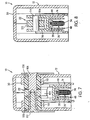
- Figure 7 is a sectional view taken along the line 7-7 of Figure 3;
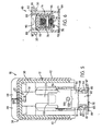
- Figure 8 is a sectional view taken along the line 8-8 of Figure 3;
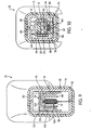
- Figure 9 is a sectional view taken along the line 9-9 of Figure 3; and
- Figure 10 is a sectional view taken along the line 10-10 of Figure 4.
- Referring now more particularly to the drawings, there is shown in Figures 1 and 2 thereof a stapler of the hammer-type, generally indicated at 10, which embodies the principles of the present invention. In general, the
stapler 10 includes an elongated fore and aft extending frame structure, generally indicated at 12, which includes a handle or hand grip portion, generally indicated at 14, at its rearward end portion, the frame structure extending forwardly of thehand grip portion 14. Mounted within theframe structure 12 for relative movement with respect thereto is a magazine assembly, generally indicated at 16, which includes structure defining a staple drive track, generally indicated at 18, and structure defining a staple stick feed track, generally indicated at 20, which leads to thedrive track 18. Also mounted on theframe structure 12 for relative movement with respect thereto is a staple driving assembly, generally indicated at 22, which includes astaple driving element 24 mounted within thedrive track 18. - The
magazine assembly 16 also includes a loading and feeding mechanism, generally indicated at 26, which is constructed and arranged to facilitate the manual loading of a staple stick into the drive track and to guide a loaded staple stick along thefeed track 20 so that a leading staple is biased to move into thedrive track 18. - The
driving element 24 and thedrive track structure 18 are constructed and arranged with respect to theframe structure 12 to move through a drive stroke incident to an operator grasping thehand grip portion 14 and manually impacting thedrive track structure 18 on a workpiece during which drive stroke the total distance of relative movement between thedriving element 24 anddrive track structure 18 is accomplished by a movement of thedriving element 24 with respect to the frame structure 12 a distance less than the total distance and a movement of thedrive track structure 18 with respect to the frame structure 12 a distance less than the total distance which, when added to the distance of movement of thedriving element 24, is equal to the total distance. A spring system, generally indicated at 28, is provided which is constructed and arranged to effect a relative movement between thedriving element 24 and thedrive track structure 18 which respect to theframe structure 12 through a return stroke during which the total distance of relative movement between thedriving element 24 and thedrive track structure 18 is accomplished by movement of thedriving element 24 with respect to the frame structure 12 a distance less than the total distance and a movement of thedrive track structure 18 with respect to the frame structure 12 a distance less than the total distance which when added to the distance of movement of thedriving element 24 is equal to the total distance. - The
drive track structure 18 and thefeed track structure 20 are constructed and arranged so that the direction of guided movement of the staple stick along thefeed track 20 is at an angle greater than 90° with respect to the direction of the drive stroke of thedriving element 24 within thedrive track 18 so that the staple crown enters thedrive track 18 while the lower penetrating ends of the staple legs are displaced angularly with respect to the direction of the drive stroke. Thedrive track structure 18 is constructed and arranged to cause the leading staple to be moved into alignment with thedrive track 18 during the drive stroke movement so as to be driven into the workpiece in the direction of the drive stroke enabling thehand grip portion 14 to be positioned for manual gripping so that the knuckles are spaced from a flat workplace surface in which a staple has been driven generally perpendicularly therein. - Referring now more particularly to Figures 3 and 4, it can be seen that the
frame structure 12 is hollow and elongated in the front-to-rear direction. Thehollow frame structure 12 is in the form of aframe member 30 which is constructed from two halves fixedly interconnected together, as by a series of fasteners or the like. The rear portion of theframe member 30, together with aresilient sleeve 32 which is mounted thereover, defines thehand grip portion 14 of theframe structure 12. Theframe member 30 extends forwardly of thehand grip portion 14. As best shown in Figure 3, this forwardly extending portion is open along a lower extent thereof, as indicated at 34, and along a lower forward extent thereof, as indicated at 36. - The
frame structure 12 also includes a front exterior cover member, generally indicated at 38, which comprises aforward wall 40 disposed in closing relation to theforward opening 36 of theframe member 30 and a pair of rearwardlybent side walls 42 overlapping forward side portions of theframe member 30. Formed integrally at the upper forward edges of thecover side walls 42 are twoshort top walls 44 which are bent inwardly toward one another to overlie the upper forward portion of theframe member 30. Thetop walls 44 are available to function as a hammering surface for staples which have been driven improperly and must be made flush with the workpiece surface. - The
feed track structure 20 of themagazine assembly 16 is preferably constructed and arranged to accommodate two staple sticks. Thefeed track structure 20 includes anelongated housing member 46 of inverted U-shaped cross-sectional configuration disposed in exterior confining relation to staples loaded in themagazine assembly 16 and anelongated core member 48 mounted for movement between (1) an operating position disposed in interior confining relation to staples loaded in themagazine assembly 16 and (2) a loading position disposed in a position to provide access for the insertion of a staple stick into thehousing member 46 through the U-shaped cross-sectional configuration thereof. In the preferred embodiment shown, thecore member 48 is also of inverted U-shaped cross-sectional configuration and is longitudinally slidably mounted within thehousing member 46 so as to extend through and rearwardly of the hollow handle portion when in the loading position thereof. - The
housing member 46 is movably mounted within theframe member 30 so that the forward end swings with respect to theframe member 30 from a normal inoperative position, as shown in Figures 1 and 3, into an upwardly displaced operative position in response to the impacting of thedrive track structure 18 with a workpiece. The extent of the movement is approximately one-half the distance of the drive stroke of thestaple driving element 24 with respect to thedrive track structure 18. The manner in which thehousing member 46 is mounted within theframe member 30 is best shown in Figure 4A. The depending legs of the U-shaped cross-section of the housing member includes two laterally spaced rearwardly extendingextensions 50 having small spaced barbs extending from the upper and lower edges thereof. Extended over eachextension 50 is a flat bearingsleeve 52 which is retained in position by the barbs. Thebearing sleeves 52 fit within laterally spacedreceiving surfaces 54 formed in the rearward end of theframe member 30 shaped to allow the bearing sleeves to pivot about a transverse axis in conjunction with a limited amount of longitudinal movement. - The mounting of the
core member 48 with respect to thehousing member 46 forms a part of the loading andfeeding mechanism 26 of themagazine assembly 16. In order to retain thecore member 48 in its operating position so that it can be selectively moved into its loading position, there is provided a releasable latch assembly, generally indicated at 56. Thelatch assembly 56 basically functions to releasably retain thecore member 48 in the operating position thereof. Preferably, it also is constructed and arranged to allow thecore member 48 when in its operating position to resiliently yieldingly move rearwardly in response to a staple jam occurrence during a drive stroke. - To this end, as best shown in Figures 4 and 10, the
latch assembly 56 includes alatch member 58 having apivot pin 60 extending laterally through the forward portion thereof. The opposite ends of thepivot pin 60 extend outwardly of thelatch member 58 and intohorizontal slots 62 formed in the legs of theU-shaped core member 48. Thelatch member 58 includes a forwardly opening bore below thepivot pin 60 which receives the rear end portion of acompression coil spring 64, the forward end of which bears against tab structure struck and bent from thecore member 48. Thespring 64 thus serves to resiliently bias thecore member 48 forwardly into its operating position and thelatch member 58 rearwardly. The rearward spring bias of thelatch member 58 is resisted by the engagement of an upwardly and rearwardly disposedlatch member catch 66 against anedge 68 defining an opening in the top wall of thehousing member 46 and by the engagement of lateral stop portions 70 (see Figure 10) of thelatch member 58 upwardly against the downwardly facing free edges of the legs of thecore member 48. Thelatch member 58 includes a rear digital engagingportion 72 which can be digitally engaged and moved downwardly to release thelatch member 58 by a clockwise pivotal action, as viewed in Figure 4, to allow thecore member 48 to be moved rearwardly from its operating position to its loading position. - At a position just forwardly of the end of
spring 64, an additional tab structure is struck and bent from thecore member 48 to secure the lower rear end of atension coil spring 74. Thecoil spring 74 extends forwardly and is trained about agrooved roller 76 rotatably carried by acore tip 78 fixed to the forward end of thecore member 48. Thecoil spring 74 extends rearwardly from theroller 76 and has its opposite end fixed to apusher 80 riding within a central longitudinal slot in the top wall of thecore member 48 and within the staple space defined by thehousing member 46 andcore member 48. Thespring 74,roller 76 andpusher 80 form a part of the loading andfeeding mechanism 26 of themagazine assembly 16. - The
core tip 78 forms a part of thedrive track structure 18. Specifically, thecore tip 78 includes a forwardly facingplanar surface 82 which defines the lower central rearward portion of thedrive track 18. The upper edge of thesurface 82 constitutes a cut-off edge for the magazine beyond which the crown of the leading fastener extends when moved into the drive track. The edge and the upper surface of thecore tip 78 extending rearwardly thereof support the staple next to the leading staple to facilitate cut-off from the staple stick during the drive stroke. - The
surface 82, as well as thedrive track 18 itself, rather than being at right angles to thefeed track 20 is at a slightly greater angle, as, for example, approximately 97°, so that when the crown of the leading staple moves from the feed track to the drive track, the penetrating free ends of the staple legs are displaced rearwardly from thesurface 82. Extending laterally outwardly from opposite sides of the lower end of thesurface 82 are integral portions which define two spaced forwardly and downwardly slanted cam surfaces 84 leading to thesurface 82 at their lower end. The cam surfaces 84 extend downwardly in flush relation with thesurface 82 to form spaced forwardly facing stop surfaces 85. The lower ends of the legs of the invertedU-shaped housing member 46 are offset laterally outwardly in order to slidably accommodate the integral core tip portions which define the cam surfaces 84. The cam surfaces 84 are in a position to be engaged by the free ends of the legs of a staple being driven in the event that it has not been aligned with thecanted drive track 18 as it reaches the level of thesurfaces 84. - The
drive track structure 18 also includes a track member which includes afront wall 86, havingparallel side walls 88 extending rearwardly therefrom. The portion of theside walls 88 which are coextensive with thehousing member 46 are fixed, as by welding or the like, to thehousing member 46. Fixed to the lower end of the track member andhousing member 46 is aplate 89 which provides a workpiece striking surface for the fixedly interconnecteddrive track structure 18 and feedtrack structure 20. - As best shown in Figure 5, the lower rearward portion of the
side walls 88 are lanced laterally outwardly along acut 87. The rearwardly facing edge of which provide surfaces which are engaged by the stop surfaces 85 of thecore tip 78 under the bias ofspring 64. - As best shown in Figures 3, 5 and 6, a
shock absorbing pad 90 is mounted on the top wall of thehousing member 46. Thepad 90 includes a pair of laterally outwardly extendingflange portions 92 which are engaged by the lower edges of theside walls 88 to retain thepad 90 in position. Extending between theside walls 88 forwardly of thepad 90 is apin 94 the forward surface of which defines the rear surface of the drive track above thehousing member 46. - The opposite ends of the
pin 94 extend outwardly of theside walls 88 and pivotally receive the legs of aU-shaped spring member 96. Thespring member 96 includes a front in-turnedupper portion 98 which serves to bias thespring member 96 to pivot about thepin 94. The lower rear surface of the U-shaped spring member engages aball 100 disposed within anopening 102 formed in the fronttrack member wall 86. Theopening 102 is shaped to allow theball 100 to protrude rearwardly into the drive track at a position which is centrally located just below the crown of a leading staple fed from the feed track into the drive track. Theball 100 is engaged by the staple crown just after the staple is stripped from its stick and this engagement facilitates alignment of the angular engagement of the end of thestaple driving element 24 with the upper surface of the staple crown which aligns the staple legs with the overly angled drive track. - The
staple driving assembly 22 includes a motion-transmitting mechanism in the form of alever 104 pivoted to theframe member 30 and interconnected between thehousing member 46 and thestaple driving element 24. As best shown in Figures 3 and 7, thelever 104 is pivoted intermediate its ends by apivot pin 106 in the form of a flat-headed bolt with an internally threaded bore in its shank. Thepivot pin 106 extends within a pair ofresilient bushings 108 disposed on opposite sides of thelever 104.Bushings 108 are seated within in-turned opposed opening-definingannular flanges 110 formed in theframe member 30. Theside walls 42 of the cover member are also apertured and countersunk to allow thepin 106 to extend therethrough in a position to receive the flat head in oneside wall 42. A smallerflat head bolt 112 is threaded within the threaded shank bore of thepin 106 to complete the pivotal mounting of the lever which by virtue of the resiliency of thebushings 108 is allowed to have a limited amount of transverse movement.Bushings 108 are preferably formed of a suitable rubber but they may be plastic or other elastomeric material. - As best shown in Figure 3 and 8, the rearward end of the
lever 104 is pivotally connected with thehousing member 46 by apivot pin 114 which extends through thelever 104 and has its ends fixed to the legs of aU-shaped bracket 116 fixed to the upper wall of thehousing member 46. The forward end of thelever 104 includes aprotusion 118 which extends within anopening 120 formed in the upper end of thestaple driving element 24. - As best shown in Figures 3 and 9, the
spring system 28 is in the form of aflat leaf spring 122 having a front end engaged with the rear end of thelever 104. A mid-portion of theflat leaf spring 122 is disposed in flexed engagement with an interior downwardly facing surface of theframe member 30 just forwardly of the forward end of thehand grip portion 14. The rear of the flat leaf spring includes two integral downwardly turnedears 124 spaced apart so as to embrace the legs of theU-shaped housing member 46. Theears 124 have downwardly openingrecesses 126 therein to receive twotabs 128 cut and bent outwardly from the legs of thehousing member 46 to retain thespring 122 in operating position. - In the operation of the hammer-
type stapler 10, the operator simply grips thehand portion 14 and swings thestapler 10 in a hammer-like movement into the workpiece where the staple is to be driven. When theplate 89 strikes the workpiece, the stapledrive track structure 18 and feedtrack structure 20 will have its movement arrested while theframe member 30 continues to move in a direction toward the workpiece. This relative movement of thehousing member 46 with respect to theframe member 30 causes thepivot pin 114 to move upwardly which, in turn, effects a downward movement of the forward end of thelever 104 which carries with it thestaple driving element 24. In this way, thestaple driving element 24 is simultaneously moved with respect to thehousing member 30 with the stapledrive track structure 18 and feedtrack structure 20. During the drive stroke of thestaple driving element 24 within the drive track, the lower end thereof will initially engage the crown of the leading staple fed from the feed track into the drive track. Since the upper surface of the crown is at an angle with respect to the lower surface of thestaple driving element 24, the interengagement therebetween will tend to both strip the leading fastener from the stick within the feed track and to move the lower end of the legs forwardly toward alignment with the drive track. Immediately after the staple is stripped, the forward lower surface of the staple crown will engage theball 100 and this engagement, in turn, will tend to align the legs of the staple with the drive track. As the staple is moved past theball 100, theball 100 moves within theopening 102 against the bias of thespring member 96 where it is retained by the presence of thestaple driving element 24 during the remainder of the drive stroke and the subsequent portion of the return stroke until the end moves above theball 100. - In the event that the legs of the staple have not been aligned with the drive track, the free ends of the legs will engage the cam surfaces 84 and, as the driving movement of the staple continues, the staple will be fully aligned with the drive track so as to enter the workpiece in a perpendicular relationship. In this regard, it will be noted that the
hand grip portion 14 is spaced from a flat workpiece which has been engaged by theplate 89 and had a staple driven perpendicularly therein. This relationship practically eliminates the problem of the operator's knuckles striking the workpiece in normal operation on floors and roofs. - During the drive stroke, the
leaf spring 122 is stressed by virtue of the upward movement of the rear end of thelever 104 so that as soon as the drive stroke is completed, thespring 122 will serve to return the stapledrive track structure 18 and feedtrack structure 20 as well as thestaple driving element 24 back into the inoperative positions thereof, as shown in Figure 3. The staples disposed within the feed track are resiliently urged in a forward direction to move the leading staple of the stick into the drive track by virtue of thepusher 80 biased by thespring 74. As soon as the lower end of thestaple driving element 24 passes the crown of the leading staple in the feed track during the return stroke, the leading staple will then be biased into the drive track to complete the cycle and condition the stapler for another driving action. - If during a drive stroke, a staple should become jammed, the
core member 48 and thesurface 82 of thecore tip 78 which is fixed thereto can move rearwardly by virtue of the interconnection of thecore member 48 with thelatch assembly 56. Specifically, thecore member 48 is capable of being moved resiliently rearwardly against the action ofspring 64 since thelatch member 58 is retained in the position shown in Figure 4 against rearward movement by virtue of the engagement of thecatch 66 with thesurface 68 and theflanges 70 with the undersides of the legs of thecore member 48 as shown in Figure 10. Since thecore member 48 can move rearwardly by virtue of theelongated slot 62 which receives thepin 60 and is biased forwardly by thespring 64, a yielding rearward movement of thecore tip 78 andcore member 48 can take place in the event of a staple jam. - When all of the staples within the feed track have been driven into the workpiece and it is desired to continue, the
latch member 58 is digitally engaged at therear portion 72 so as to pivot thelatch member 58 from the core member retaining position shown in Figure 4 in a clockwise direction into a core member releasing position, wherein thecatch 66 extends below theopening 68, thus allowing the entire core to slide rearwardly and exposing the interior of thehousing member 46 through theopening 34. The supply of staples can be replenished by simply dropping a staple stick into thehousing member 46 in an inverted relation with the crowns of the stick downwardly. While the opening is not big enough to receive two sticks, the arrangement is such that a first stick can be moved into thehousing member 46 and then moved rearwardly in order to provide space for the insertion of a second stick. After two staple sticks have been loaded within thehousing member 46, thecore member 48 is moved forwardly and during the end of this movement, which is determined by the engagement of forwardly facing stop surfaces 85 with the rearwardly facing edges ofcuts 87, thelatch member 56 will be cammed by the forward surface of thecatch 66 from its core retaining position into its core releasing position and then returned by the action of thespring 64 into its core retaining position to enable the stapler to again be used to drive staples. - In addition to the statements setting out aspects of the invention in the introduction of this specification, the invention will now be set out in a further general aspect.
- According to the present invention in a further aspect there is provided a stapler, preferably a hammer-type stapler, comprising a frame structure including a hand grip portion; a magazine assembly including a staple drive track and a staple feed track leading to said staple drive track; and a staple driving element mounted for movement along said staple drive track through successive cycles each including a drive stroke and a return stroke; said driving element being arranged to move through a drive stroke upon an operator grasping said hand grip portion and manually impacting the drive track on a workpiece to arrest the movement of the drive track on the workpiece while said staple driving element continues to move toward said workpiece with respect to the arrested drive track; and means for producing during a drive stroke movement of the driving element along the drive track by combined movement of both the driving element relative to the frame structure and of the drive track relative to the frame structure.
- Preferably said staple feed track is coupled to said staple drive track to move therewith during a drive stroke, and said motion producing means is coupled between said feed track, said frame structure, and said staple driving element. The motion producing means may comprise a lever pivoted on said frame structure and coupled at one distal end to said feed track and at the other distal end to the driving element.
- It is to be appreciated that where features of the invention are set out herein with regard to apparatus according to the invention, such features may also be provided with regard to a method according to the invention, and visa versa.
- In particular there is provided in accordance with the invention a method of stapling using a hammer-type stapler comprising a frame structure including a hand grip portion, a magazine assembly including a staple drive track and a staple feed track leading to said staple drive track, and staple driving element mounted for movement along said staple drive track through successive cycles each including a drive stroke and a return stroke; the method comprising the steps of grasping said hand grip portion and manually impacting the drive track on a workpiece to arrest the movement of the drive track on the workpiece while said staple driving element continues to move toward said workpiece with respect to the arrested drive track; and producing during a drive stroke movement of the driving element along the drive track by combined movement of both the driving element relative to the frame structure and of the drive track relative to the frame structure.
Claims (22)
- A hammer-type stapler (10) comprising
a frame structure (12) including a hand grip portion (14) constructed and arranged to be manually grasped by an operator,
a magazine assembly (16) including structure defining a staple drive track (18) mounted for relative movement with respect to said frame structure (12) and structure defining a staple stick feed track (20) leading to said drive track (18),
a staple driving assembly (22) including a staple driving element (24) mounted for movement within said drive track (18) through successive cycles each including a drive stroke and a return stroke,
said magazine assembly (16) including a loading and feeding mechanism constructed and arranged to facilitate the manual loading of a staple stick into said feed track (20) and to feed a loaded staple stick along said feed track (20) in a feed direction so that successive leading staples are moved into said drive track (18) to be driven therefrom in a drive direction into a workpiece during the drive stroke of successive cycles of said driving element (24), and
said driving element (24) and said drive track structure (18) being constructed and arranged with respect to said frame structure (12) to move through a drive stroke incident to an operator grasping said hand grip portion (14) and manually impacting the drive track structure (18) on a workpiece to arrest the movement of the drive track structure (18) on the workpiece while said frame structure (12) and said staple driving element (24) continue to move toward said workpiece with respect to the arrested drive track structure (18);
characterised in that
said driving element (24) is mounted for relative movement with respect to said frame structure and is constructed and arranged with respect to the frame structure (12) and said drive track structure (18) such that the continued movement of said driving element (24) toward said workpiece with respect to the arrested drive track structure (18) is further and faster than the continued movement of the frame structure (12) toward said workpiece with respect to the arrested drive track structure (18) enabling said driving element (24) to effect a drive stroke through said drive track and to drive a staple therein into said workpiece while said frame structure (12) is undergoing a relative movement with respect to said drive track structure (18) which is less than substantially equal to the relative movement of said driving element (24) with respect to said drive track structure (18) during the drive stroke of said driving element (24),
and a spring system (28) is constructed and arranged to effect opposite relative movements between said driving element (24) and drive track structure (18) with respect to said frame structure during which said driving element (24) is moved within said drive track (18) through a return stroke. - A hammer-type stapler as defined in claim 1 wherein said hand grip portion (14) forms a rearward portion of said frame structure (12) which extends forwardly therefrom, said feed track structure (20) including an elongated housing member (46) extending within said frame structure (12) in a direction front to rear with a rearward end portion thereof movably supported on a rearward portion of said frame structure (12), said drive track structure (18) being fixed to a forward end portion of said housing member (46) so that when an operator grasps the handle portion (14) and impacts the drive track structure (18) on a workpiece the frame structure (12) continues to move with a pivotal action with respect to the housing member, said driving assembly including a motion transmitting mechanism for transmitting the relative movement between said frame structure and said housing member (46) to a relative movement of said driving element (24) with respect to said frame structure (12) so that the relative movements of both the driving element (24) and the drive track structure (18) with respect to said frame structure (12) during the impacting operation results in a relative drive stroke movement of said driving element (24) within said drive track (18).
- A hammer-type stapler as defined in claim 2 wherein said motion-transmitting mechanism includes a lever (104) having an intermediate portion thereof mounted on a forward portion of said frame structure above said housing member (46) for pivotal movement about a transverse axis with respect to said frame structure (12), said lever (104) having a rearward end portion connected to move with said housing member (46) and a forward end portion connected to move with said driving element (24).
- A hammer-type stapler as defined in claim 3 wherein the intermediate portion of said lever (104) is pivotally mounted on said frame structure (12) by a resilient bushing (108) which allows said lever to have a limited amount of resiliently yielding movement in a direction transverse to the pivotal axis thereof.
- A hammer-type stapler as defined in claim 4 wherein the connection between the rearward end portion of said lever (104) and housing member (12) is a pivotal connection about an axis parallel with the pivotal axes of said lever (104) and said housing member (12).
- A hammer-type stapler as defined in claim 4 wherein the connection between the forward end of said lever (104) and said driving element (24) is a sliding engagement of a forward end portion of said lever (104) within an opening in an end of said driving element (24) opposite from an end thereof which engages a staple during the drive stroke thereof.
- A hammer-type stapler as defined in claim 6 wherein said housing member (46) is movably mounted on said frame structure (12) by a pair of transversely spaced rearwardly extending semi-circular bearing sleeves slidably and pivotally received in suitably contoured surfaces at the rearward portion of said frame structure (12).
- A hammer-type stapler as defined in claim 7 wherein said spring system (28) includes a leaf spring (122) having a rear end portion connected with said housing member (46), an intermediate portion engaging said frame structure (12) and a forward end engaging the rear end of said lever (104) to bias the same in a direction to cause said driving element (24) to be moved through said return stroke.
- A hammer-type stapler as defined in claim 1 or 8 wherein said drive track structure (18) and said staple feed track structure (20) are constructed and arranged so that the direction of guided movement of a staple stick along said feed track (20) is at an angle greater than 90° with respect to the direction of the drive stroke of said driving element (24) within said drive track (18) so that a staple crown of a leading staple enters the drive track (18) while a pair of staple legs of a leading staple is displaced angularly with respect to the direction of the drive stroke, and wherein said drive track structure (18) is constructed and arranged to cause the leading staple to be moved into alignment with the drive track (18) during the driving movement imparted to the crown thereof during said drive stroke enabling the hand grip portion (14) to be positioned for manual gripping so that knuckles of a hand gripping said hand grip portion (14) are spaced from a flat workpiece surface in which a staple has been driven generally perpendicularly therein.
- A hammer-type stapler as defined in claim 9 wherein said staple drive track (18) defining structure includes a staple-aligning assembly constructed and arranged to be yieldingly engaged beneath a forward crown portion of a leading staple disposed in said drive track (18) slightly after said leading staple has been stripped from the staple stick during the drive stroke thereof to cause a pair of legs of the staple to move into alignment with the crown of the staple within said drive track (18).
- A hammer-type stapler as defined in claim 10 wherein said staple-aligning assembly includes a ball (100) mounted for fore and aft movement in said drive track structure (18) in a position slightly below a crown of a leading staple moved into said drive track by said magazine loading and feeding mechanism, and a spring constructed and arranged to bias said ball (100) so that a rearward portion thereof enters said drive track (18) to be engaged and moved forwardly against the bias of said spring as the crown of the staple is moved thereby during the drive stroke thereof.
- A hammer-type stapler as defined in claim 11 wherein said staple drive track (18) defining structure includes a staple-camming structure disposed rearwardly of said drive track constructed and arranged to engage a pair of free ends of a pair of legs of a staple being driven in misalignment with said drive track (18) and to cam the free ends of the legs of the staple into alignment with said drive track (18) before moving outwardly thereof into the workpiece during the drive stroke thereof.
- A hammer-type stapler as defined in claim 1 wherein said feed track structure includes an elongated exterior housing member (46) for containing a plurality of staple sticks containing staple crowns and staple legs in exterior confining relation to the staple crowns and the staple legs, and a core member movable with respect to said housing member (46) between (1) an operating position disposed in interior confining relation to the staple crowns and staple legs and (2) a loading position withdrawn from said operative position so as to enable a staple stick to be loaded into said exterior housing member (46) in a direction toward a portion thereof confining the staple stick above the staple crowns thereof.
- A hammer-type stapler as defined in claim 13 wherein said core member is mounted to slide longitudinally with respect to said housing member (46) between the operating and loading positions thereof.
- A hammer-type stapler as defined in claim 14 wherein said handle portion (14) is hollow and said core member (48) extends outwardly through and rearwardly beyond said hollow handle portion (14) when in said loading position.
- A hammer-type stapler as defined in claim 15 wherein said magazine assembly includes a releasable latch assembly (56) constructed and arranged to releasably retain said core member (48) in the operating position thereof.
- A hammer-type stapler as defined in claim 16 wherein said latch assembly (56) is constructed and arranged to retain said core member (48) in the operating position thereof in a relationship enabling said core member (48) to resiliently yieldingly move rearwardly in response to a staple jam occurrence during a staple drive stroke.
- A hammer-type stapler as defined in claim 17 wherein said latch assembly (56) includes a latch member (58) mounted on the rearward end portion of said core member (1) for pivotal movement about a transverse axis between a core-retaining position and a core-releasing position and (2) for forward and rearward longitudinal movements with respect to said core member (48), and a spring (64) acting between said housing member (46) and said latch member (58) resiliently biasing said latch member (58) into said core-retaining position, the arrangement being such that when said latch member (58) is in said core-retaining position said core member can be moved rearwardly against the bias of said spring (64).
- A hammer-type stapler comprising:a frame structure (12) including a hand grip portion (14);a magazine assembly (16) including a staple drive track (18) and a staple feed track (20) leading to said staple drive track; anda staple driving element (24) mounted for movement along said staple drive track (18) through successive cycles each including a drive stroke and a return stroke;said driving element (24) being arranged to move through a drive stroke upon an operator grasping said hand grip portion and manually impacting the drive track (18) on a workpiece to arrest the movement of the drive track (18) on the workpiece while said staple driving element (24) continues to move toward said workpiece with respect to the arrested drive track (18);characterised by means (104) for producing during a drive stroke movement of the driving element (24) along the drive track (18) by combined movement of both the driving element (24) relative to the frame structure (12) and of the drive track (18) relative to the frame structure (12).
- A stapler according to Claim 19 in which said staple feed track (20) is coupled to said staple drive track (18) to move therewith during a drive stroke, and said motion producing means (104) is coupled between said feed track (20), said frame structure (12), and said staple driving element (24).
- A stapler according to Claim 20 in which said motion producing means comprises a lever (104) pivoted on said frame structure (12) and coupled at one distal end to said feed track (20) and at the other distal end to the driving element (24).
- A method of stapling using a hammer-type stapler comprising a frame structure (12) including a hand grip portion (14), a magazine assembly (16) including a staple drive track (18) and a staple feed track (20) leading to said staple drive track, and staple driving element (24) mounted for movement along said staple drive track (18) through successive cycles each including a drive stroke and a return stroke; the method comprising the steps of:grasping said hand grip portion and manually impacting the drive track (18) on a workpiece to arrest the movement of the drive track (18) on the workpiece while said staple driving element (24) continues to move toward said workpiece with respect to the arrested drive track (18);characterised by producing during a drive stroke movement of the driving element (24) along the drive track (18) by combined movement of both the driving element (24) relative to the frame structure (12) and of the drive track (18) relative to the frame structure (12).
Applications Claiming Priority (2)
| Application Number | Priority Date | Filing Date | Title |
|---|---|---|---|
| US09/083,501 US5975401A (en) | 1998-05-22 | 1998-05-22 | Hammer-type stapler with relatively movable driver and magazine |
| US83501 | 1998-05-22 |
Publications (3)
| Publication Number | Publication Date |
|---|---|
| EP0960695A2 EP0960695A2 (en) | 1999-12-01 |
| EP0960695A3 EP0960695A3 (en) | 2004-03-24 |
| EP0960695B1 true EP0960695B1 (en) | 2006-08-09 |
Family
ID=22178750
Family Applications (1)
| Application Number | Title | Priority Date | Filing Date |
|---|---|---|---|
| EP99303971A Expired - Lifetime EP0960695B1 (en) | 1998-05-22 | 1999-05-21 | Hammer-type stapler |
Country Status (4)
| Country | Link |
|---|---|
| US (1) | US5975401A (en) |
| EP (1) | EP0960695B1 (en) |
| CA (1) | CA2272800A1 (en) |
| DE (1) | DE69932669T2 (en) |
Families Citing this family (16)
| Publication number | Priority date | Publication date | Assignee | Title |
|---|---|---|---|---|
| US6179194B1 (en) * | 1999-10-22 | 2001-01-30 | Mack R. Morton | Cartridge fed stapler |
| US6550660B1 (en) | 2001-08-03 | 2003-04-22 | Edmund M. Chlebowski | Hammer-type stapler with tab feeder |
| US7232050B2 (en) * | 2005-02-21 | 2007-06-19 | Allan Omli, Llc | Manually actuated fastener driver with fastener cap reservoir and advancement mechanism |
| US7481346B2 (en) | 2006-01-13 | 2009-01-27 | National Nail Corporation | Hammer-type stapler tool |
| US7628305B2 (en) * | 2006-06-16 | 2009-12-08 | National Nail Corporation | Impact fastener tool with cap feed arrangement |
| US7530483B2 (en) | 2006-06-16 | 2009-05-12 | National Nail Corporation | Impact fastener tool with cap feed |
| US8561868B2 (en) * | 2006-11-03 | 2013-10-22 | Arrow Fastener Co., Inc. | Device for driving flexible strips of fasteners |
| GB2445017A (en) * | 2006-12-20 | 2008-06-25 | Elsa Lenoria Conreaux | Hand-held stapler |
| US20080173690A1 (en) * | 2007-01-23 | 2008-07-24 | Pneutools, Incorporated | Slap hammer with cap magazine and feeder |
| SE0700329L (en) * | 2007-02-12 | 2008-02-26 | Isaberg Rapid Ab | hammers |
| US20100116864A1 (en) * | 2008-11-07 | 2010-05-13 | Pneutools, Incorporated | Motorized fastener applicator |
| DE202010001033U1 (en) | 2010-01-15 | 2010-05-20 | FÜRST, Stefan | shock stapler |
| USD630072S1 (en) * | 2010-03-22 | 2011-01-04 | Arrow Fastener Co., Llc | Fastening tool |
| US20140231486A1 (en) * | 2013-02-19 | 2014-08-21 | Milwaukee Electric Tool Corporation | Stapler |
| US10730173B2 (en) * | 2015-08-24 | 2020-08-04 | Stanley Black & Decker, Inc. | Hammer tacker |
| TWI902354B (en) * | 2024-07-18 | 2025-10-21 | 豐民金屬工業股份有限公司 | Hammer tacker |
Family Cites Families (15)
| Publication number | Priority date | Publication date | Assignee | Title |
|---|---|---|---|---|
| US1166190A (en) * | 1915-03-17 | 1915-12-28 | Charles W Dawson | Stapling device. |
| US1671733A (en) * | 1925-07-25 | 1928-05-29 | Boston Wire Stitcher Co | Stapling machine or tacker |
| US1687871A (en) * | 1926-12-04 | 1928-10-16 | Boston Wire Stitcher Co | Stapling machine or tacker |
| US2332257A (en) * | 1942-02-18 | 1943-10-19 | Hotchkiss Co E H | Fastener driving machine |
| US2325341A (en) * | 1942-02-18 | 1943-07-27 | Hotchkiss Co E H | Fastener driving machine |
| US2432853A (en) * | 1943-06-19 | 1947-12-16 | Vail Mfg Company | Implement for driving staples |
| US2537601A (en) * | 1947-03-21 | 1951-01-09 | Hotchkiss Co E H | Stapling hammer |
| US2501703A (en) * | 1948-03-24 | 1950-03-28 | Nat Autostitch Corp | Stapling tool |
| US2645773A (en) * | 1950-08-19 | 1953-07-21 | Nat Autostitch Corp | Removable staple driver guide for staple driving implements |
| US2667639A (en) * | 1950-10-05 | 1954-02-02 | Tok Inc | Cam action magazine type tack hammer |
| US2661999A (en) * | 1951-08-17 | 1953-12-08 | Arrow Fastener Co Inc | Hammer type stapler |
| US2653317A (en) * | 1951-09-01 | 1953-09-29 | Spotnails | Hammer type stapling machine |
| US2664565A (en) * | 1951-10-26 | 1954-01-05 | Richard A Percoco | Staple driver |
| US2896210A (en) * | 1957-02-27 | 1959-07-28 | Arrow Fastener Co Inc | Hammer type staplers |
| US4598852A (en) * | 1982-04-06 | 1986-07-08 | Swingline Inc. | Fastener driving tool including fastener deformation and guidance arrangements |
-
1998
- 1998-05-22 US US09/083,501 patent/US5975401A/en not_active Expired - Lifetime
-
1999
- 1999-05-21 DE DE69932669T patent/DE69932669T2/en not_active Expired - Lifetime
- 1999-05-21 CA CA002272800A patent/CA2272800A1/en not_active Abandoned
- 1999-05-21 EP EP99303971A patent/EP0960695B1/en not_active Expired - Lifetime
Also Published As
| Publication number | Publication date |
|---|---|
| US5975401A (en) | 1999-11-02 |
| DE69932669D1 (en) | 2006-09-21 |
| CA2272800A1 (en) | 1999-11-22 |
| EP0960695A2 (en) | 1999-12-01 |
| EP0960695A3 (en) | 2004-03-24 |
| DE69932669T2 (en) | 2007-08-09 |
Similar Documents
| Publication | Publication Date | Title |
|---|---|---|
| US6012623A (en) | Hammer-type stapler with canted drive track | |
| EP0960695A2 (en) | Hammer-type stapler | |
| US5328075A (en) | Manual staple gun | |
| CA2164861C (en) | Forward acting, staple machine with passive release | |
| CA1238452A (en) | Reversible staple feeder shoe and door system for the magazine of a staple driving tool | |
| US7513403B2 (en) | Idle driving operation preventing devices for fastener driving tools, and fastener driving tools having such devices | |
| US5322189A (en) | Fastener feeding mechanism in fastener driving device | |
| US7516532B2 (en) | Pusher bearing and pusher block for magazine feeder | |
| US8251273B2 (en) | Continuous feed cap mechanism | |
| EP0640445B1 (en) | Spring actuated fastener driving tool | |
| EP0828588B1 (en) | Hand tool | |
| US20170190039A1 (en) | Stapler | |
| US5018275A (en) | Cutting device | |
| US7836970B2 (en) | Impact fastener tool with cap feed | |
| AU2004261621A1 (en) | Fastener-driving tool | |
| US20080156844A1 (en) | Staple gun | |
| US20100320251A1 (en) | Nailer | |
| GB2032327A (en) | Stapler drive and feed mechanisms | |
| US20080173690A1 (en) | Slap hammer with cap magazine and feeder | |
| US20220274236A1 (en) | Slap hammer with cap dispenser | |
| US5121868A (en) | Stapler mechanism including jam clearing device | |
| US4434929A (en) | Hammer with magazine nail feed | |
| US3172122A (en) | Plier type staplers | |
| US20200376639A1 (en) | Multiple strike fastener driver/holder | |
| CN115229737B (en) | Hammer with nail box and use method thereof |
Legal Events
| Date | Code | Title | Description |
|---|---|---|---|
| PUAI | Public reference made under article 153(3) epc to a published international application that has entered the european phase |
Free format text: ORIGINAL CODE: 0009012 |
|
| AK | Designated contracting states |
Kind code of ref document: A2 Designated state(s): AT BE CH CY DE DK ES FI FR GB GR IE IT LI LU MC NL PT SE |
|
| AX | Request for extension of the european patent |
Free format text: AL;LT;LV;MK;RO;SI |
|
| PUAL | Search report despatched |
Free format text: ORIGINAL CODE: 0009013 |
|
| AK | Designated contracting states |
Kind code of ref document: A3 Designated state(s): AT BE CH CY DE DK ES FI FR GB GR IE IT LI LU MC NL PT SE |
|
| AX | Request for extension of the european patent |
Extension state: AL LT LV MK RO SI |
|
| RIC1 | Information provided on ipc code assigned before grant |
Ipc: 7B 25C 5/11 B Ipc: 7B 25D 1/00 A |
|
| 17P | Request for examination filed |
Effective date: 20040827 |
|
| AKX | Designation fees paid |
Designated state(s): DE FR GB |
|
| GRAP | Despatch of communication of intention to grant a patent |
Free format text: ORIGINAL CODE: EPIDOSNIGR1 |
|
| GRAS | Grant fee paid |
Free format text: ORIGINAL CODE: EPIDOSNIGR3 |
|
| GRAA | (expected) grant |
Free format text: ORIGINAL CODE: 0009210 |
|
| AK | Designated contracting states |
Kind code of ref document: B1 Designated state(s): DE FR GB |
|
| REG | Reference to a national code |
Ref country code: GB Ref legal event code: FG4D |
|
| REF | Corresponds to: |
Ref document number: 69932669 Country of ref document: DE Date of ref document: 20060921 Kind code of ref document: P |
|
| ET | Fr: translation filed | ||
| PLBE | No opposition filed within time limit |
Free format text: ORIGINAL CODE: 0009261 |
|
| STAA | Information on the status of an ep patent application or granted ep patent |
Free format text: STATUS: NO OPPOSITION FILED WITHIN TIME LIMIT |
|
| 26N | No opposition filed |
Effective date: 20070510 |
|
| PGFP | Annual fee paid to national office [announced via postgrant information from national office to epo] |
Ref country code: GB Payment date: 20140527 Year of fee payment: 16 |
|
| PGFP | Annual fee paid to national office [announced via postgrant information from national office to epo] |
Ref country code: DE Payment date: 20140529 Year of fee payment: 16 Ref country code: FR Payment date: 20140519 Year of fee payment: 16 |
|
| REG | Reference to a national code |
Ref country code: DE Ref legal event code: R119 Ref document number: 69932669 Country of ref document: DE |
|
| GBPC | Gb: european patent ceased through non-payment of renewal fee |
Effective date: 20150521 |
|
| REG | Reference to a national code |
Ref country code: FR Ref legal event code: ST Effective date: 20160129 |
|
| PG25 | Lapsed in a contracting state [announced via postgrant information from national office to epo] |
Ref country code: DE Free format text: LAPSE BECAUSE OF NON-PAYMENT OF DUE FEES Effective date: 20151201 Ref country code: GB Free format text: LAPSE BECAUSE OF NON-PAYMENT OF DUE FEES Effective date: 20150521 |
|
| PG25 | Lapsed in a contracting state [announced via postgrant information from national office to epo] |
Ref country code: FR Free format text: LAPSE BECAUSE OF NON-PAYMENT OF DUE FEES Effective date: 20150601 |