EP0960646A1 - Adsorption gas dryer - Google Patents
Adsorption gas dryer Download PDFInfo
- Publication number
- EP0960646A1 EP0960646A1 EP98304188A EP98304188A EP0960646A1 EP 0960646 A1 EP0960646 A1 EP 0960646A1 EP 98304188 A EP98304188 A EP 98304188A EP 98304188 A EP98304188 A EP 98304188A EP 0960646 A1 EP0960646 A1 EP 0960646A1
- Authority
- EP
- European Patent Office
- Prior art keywords
- gas
- valve
- manifold
- towers
- adsorption dryer
- Prior art date
- Legal status (The legal status is an assumption and is not a legal conclusion. Google has not performed a legal analysis and makes no representation as to the accuracy of the status listed.)
- Withdrawn
Links
Images


Classifications
-
- B—PERFORMING OPERATIONS; TRANSPORTING
- B01—PHYSICAL OR CHEMICAL PROCESSES OR APPARATUS IN GENERAL
- B01D—SEPARATION
- B01D53/00—Separation of gases or vapours; Recovering vapours of volatile solvents from gases; Chemical or biological purification of waste gases, e.g. engine exhaust gases, smoke, fumes, flue gases, aerosols
- B01D53/02—Separation of gases or vapours; Recovering vapours of volatile solvents from gases; Chemical or biological purification of waste gases, e.g. engine exhaust gases, smoke, fumes, flue gases, aerosols by adsorption, e.g. preparative gas chromatography
- B01D53/04—Separation of gases or vapours; Recovering vapours of volatile solvents from gases; Chemical or biological purification of waste gases, e.g. engine exhaust gases, smoke, fumes, flue gases, aerosols by adsorption, e.g. preparative gas chromatography with stationary adsorbents
- B01D53/0407—Constructional details of adsorbing systems
- B01D53/0415—Beds in cartridges
-
- B—PERFORMING OPERATIONS; TRANSPORTING
- B01—PHYSICAL OR CHEMICAL PROCESSES OR APPARATUS IN GENERAL
- B01D—SEPARATION
- B01D53/00—Separation of gases or vapours; Recovering vapours of volatile solvents from gases; Chemical or biological purification of waste gases, e.g. engine exhaust gases, smoke, fumes, flue gases, aerosols
- B01D53/26—Drying gases or vapours
- B01D53/261—Drying gases or vapours by adsorption
-
- B—PERFORMING OPERATIONS; TRANSPORTING
- B60—VEHICLES IN GENERAL
- B60T—VEHICLE BRAKE CONTROL SYSTEMS OR PARTS THEREOF; BRAKE CONTROL SYSTEMS OR PARTS THEREOF, IN GENERAL; ARRANGEMENT OF BRAKING ELEMENTS ON VEHICLES IN GENERAL; PORTABLE DEVICES FOR PREVENTING UNWANTED MOVEMENT OF VEHICLES; VEHICLE MODIFICATIONS TO FACILITATE COOLING OF BRAKES
- B60T17/00—Component parts, details, or accessories of power brake systems not covered by groups B60T8/00, B60T13/00 or B60T15/00, or presenting other characteristic features
- B60T17/002—Air treatment devices
- B60T17/008—Silencer devices
-
- F—MECHANICAL ENGINEERING; LIGHTING; HEATING; WEAPONS; BLASTING
- F01—MACHINES OR ENGINES IN GENERAL; ENGINE PLANTS IN GENERAL; STEAM ENGINES
- F01N—GAS-FLOW SILENCERS OR EXHAUST APPARATUS FOR MACHINES OR ENGINES IN GENERAL; GAS-FLOW SILENCERS OR EXHAUST APPARATUS FOR INTERNAL COMBUSTION ENGINES
- F01N13/00—Exhaust or silencing apparatus characterised by constructional features ; Exhaust or silencing apparatus, or parts thereof, having pertinent characteristics not provided for in, or of interest apart from, groups F01N1/00 - F01N5/00, F01N9/00, F01N11/00
- F01N13/08—Other arrangements or adaptations of exhaust conduits
- F01N13/087—Other arrangements or adaptations of exhaust conduits having valves upstream of silencing apparatus for by-passing at least part of exhaust directly to atmosphere
-
- B—PERFORMING OPERATIONS; TRANSPORTING
- B01—PHYSICAL OR CHEMICAL PROCESSES OR APPARATUS IN GENERAL
- B01D—SEPARATION
- B01D2259/00—Type of treatment
- B01D2259/40—Further details for adsorption processes and devices
- B01D2259/40003—Methods relating to valve switching
-
- B—PERFORMING OPERATIONS; TRANSPORTING
- B01—PHYSICAL OR CHEMICAL PROCESSES OR APPARATUS IN GENERAL
- B01D—SEPARATION
- B01D53/00—Separation of gases or vapours; Recovering vapours of volatile solvents from gases; Chemical or biological purification of waste gases, e.g. engine exhaust gases, smoke, fumes, flue gases, aerosols
- B01D53/02—Separation of gases or vapours; Recovering vapours of volatile solvents from gases; Chemical or biological purification of waste gases, e.g. engine exhaust gases, smoke, fumes, flue gases, aerosols by adsorption, e.g. preparative gas chromatography
- B01D53/04—Separation of gases or vapours; Recovering vapours of volatile solvents from gases; Chemical or biological purification of waste gases, e.g. engine exhaust gases, smoke, fumes, flue gases, aerosols by adsorption, e.g. preparative gas chromatography with stationary adsorbents
- B01D53/0407—Constructional details of adsorbing systems
- B01D53/0446—Means for feeding or distributing gases
Definitions
- Adsorption dryers for compressed air and gases have been known for many years and are widely used throughout the world. Although other types of dryer are available, such as deliquescent and refrigeration dryers, these cannot give a pressure dewpoint as low as that achieved by adsorption dryers and which is essential for many applications.
- adsorption dryers are dual tower dryers. That is to say, they include two towers of desiccant material (commonly known as beds) one of which is 'on stream' drying the gas whilst the other is being regenerated.
- the gas to be dried is passed through the desiccant bed of the on-stream tower continuously, in one direction, during a drying cycle. Then, after a predetermined time interval (this interval being chosen such that the bed will have adsorbed sufficient moisture) the inlet gas is switched to the desiccant bed of the other tower and the first desiccant bed is regenerated by some suitable procedure such as heating, evacuation or passing a purge gas through it, usually in a flow direction opposite to the flow of gas to be dried.
- Adsorption dryers are available in at least two distinct types: heat regenerative and heatless.
- a heat regenerative dryer uses heat in one form or another to reactivate the wet desiccant bed normally in conjunction with a flow of purge gas.
- a heatless dryer uses a purge flow of dry gas, which is usually a proportion of gas from the on stream tower, the purge gas being passed through the regenerating bed at a lower pressure than the gas in the on-stream tower.
- Both types of dryer are normally operated on a fixed time cycle for drying and regeneration and both cycles are usually of an equal duration, or they can be operated in a variable cycle.
- the cycle times for heat regenerative dryers are usually measured in hours whereas for heatless dryers they are measured in minutes.
- valves To control the flow of gas from one tower to the other, and to control the purge gas, a series of valves is employed. These valves most typically include, two inlets valves which switch the gas from one tower to the other, two exhaust valves which control the duration of purge gas flow and repressurisation of the towers, and two outlet check valves. In addition to these six valves, a number of other valves such as purge check valves, repressurisation valves, additional exhaust restrictor valves and so forth may be required.
- an adsorption dryer characterised by a first and a second drying tower each having a first port and a second port through which gas can pass into or out of the tower; a first and a second manifold connected respectively to the first and the second ports of both towers, the manifolds, each including integral gas passages, each port of the towers being in communication with a gas passage, and the manifolds each including at least one integral valve seat upon which a valve actuator is mounted to constitute a valve for controlling flow of gas through the gas passages.
- the number of joints is minimised so improving reliability and reducing leakage and the complexity of assembly.
- the passages within the manifold can be formed to a length and shape, and the valve seats can be positioned to exactly correspond with the positions of the towers, unlike in the prior art where the positions of the pipes is determined by the positions of the valve ports.
- Each manifold may be formed as a casting, for example of aluminium alloy, spheroidal graphite iron, or plastic material such as polycarbonate.
- one manifold acts as a wet gas inlet and the other manifold as the dry gas outlet.
- a dryer embodying the present invention most commonly comprises two similar towers, each having an upper and a lower port, and upper and lower manifolds, the upper manifold being connected to the upper ports of both of the towers and the lower manifold being connected to the lower ports of both of the towers.
- a drier embodying the invention may be to heatless or heat reactivated, upflow or downflow types of adsorption dryers.
- a drier embodying the invention includes integrally within at least one manifold a 2/2 valve to having a third port and an integral bypass tee. This allows a compact configuration of the valves and can help to reduces the length of the flow passages (and hence pressure drop) and also considerably reduces the physical size of the dryer by allowing substantially all of the valves and gas passages to be disposed between the towers.
- a control system for a dryer embodying the invention may be positioned within or on a manifold.
- valves have been attached through pipework to the towers by means of screwed unions or gaskets. These are difficult to seal and are prone to subsequent leakage.
- embodiments of the present invention may use O-rings located in nozzles of the towers to provide a seal with the manifold These O-rings serve two purposes in that they not only provide compound sealing between the manifold and the vessel towers, but that they also captively hold desiccant support screens in place in the towers so that the manifolds can be removed from the towers without fear that the desiccant beads will fall out of the towers, thus making maintenance a much simpler task.
- Embodiments of the invention can incorporate, for example, poppet or piston actuated valves or diaphragm valves.
- FIG 1 shows a typical prior art adsorption dryer.
- the dryer comprises first and second drying towers 10, 12 each containing desiccant material.
- the towers 10,12 are generally cylindrical and are disposed in an upright orientation.
- Gas to be dried is received by an inlet pipe 14 from where it is conveyed to the towers 10,12 through an inlet system 16 of pipes and valves mounted above the towers 10,12. Gas exiting from the towers 10,12 is received by an outlet system 18 of pipes and valves mounted below the towers 10,12.
- each system is constructed from commercially available solenoid-operated valves 20 with either butt welded or threaded malleable iron interconnecting pipework 22.
- the systems include a large number of joints, each of which is a site of a potential leak and an obstacle to smooth gas flow, and each of which contributes to the labour involved in construction of the dryer. Operation of the valves is controlled by a control unit 24.
- FIG. 2 to 9 An embodiment of the invention is illustrated in Figures 2 to 9.
- a heatless downflow dryer utilising diaphragm valves is used as an example.
- the invention is not restricted in application to dryers of this type.
- a dryer embodying the invention comprises first and second drying towers 30,32, each containing desiccant material.
- the towers 30,32 are generally cylindrical and are disposed in an upright orientation.
- Each tower 30,32 has an upper and a lower port through which gas can pass into and out of the tower.
- An inlet manifold 34 is connected to the upper ports of both towers 30,32 and an outlet manifold 36 is connected to the lower ports of both towers 30,32.
- the two manifolds are constructed as around identical castings 40.
- Various materials can be used for the casting ranging from Aluminium alloys to Spheroidal Graphite Iron to Polycarbonate composite plastics.
- Each casting 40 is symmetrical about a centre plane X between the towers 30,32.
- each casting 40 is formed four valve seats 42,44.
- the valve seats 42,44 are disposed in line Y in a direction perpendicular to the plane of symmetry X (see Figure 8), such that two of the valve seats 42 are comparatively further from the plane X such that the other two of the valve seats 44 are closer to the plane X.
- FIGS 5 to 7 show diagrammatically the valve seats 42, 44 and a surrounding region of the manifold 40. It should be understood that these figures show a portion of an integral casting. These are not separate components.
- the first gas passage 46 carries gas to the connection with the port of the corresponding tower 32,34.
- the second gas passage 48 carries gas to a first external connection point of the casting 40.
- the third gas passage 50 carries gas adjacent valve seat 44 closer to the plane X.
- the two valve seats 44 closer to the plane X each additionally communicate with one another through a fourth gas passage 52.
- a side branch 54 of the fourth gas passage 52 extends to carry gas to a central external connection point of the casting.
- Each of the valve 44, 46 seats includes a cylindrical valve chamber 58 within the casting.
- Each chamber 58 has one open end, and the open end is surrounded by an annular first sealing surface 60.
- the first and third gas passages 46,50 enter the chamber 58 at respective radial openings.
- the second gas passage 48 enters the chamber 58 within a tubular formation 70 formed integrally with the casting 40.
- the tubular formation 70 enters the chamber 58 radially, in a direction at right angles to the first and the third gas passages 46,50, and then turns through a bend of 90° such that an end portion of it is concentric with the chanter 58.
- An end surface of the tubular formation forms an annular second sealing surface 62 concentric with, and spaced axially into the chanter 58 from, the first sealing surface 60.
- the fourth gas passage 52 enters the chamber 58 at a radial opening.
- the third gas passage 50 enters the chanter 58 within a tubular formation 68 formed integrally with the casting.
- the tubular formation 68 enters the chanter 58 radially, in a direction diametrically opposite to the third gas passage 50, and then turns through a bend of 90° such that an end portion of it is concentric with the chanter 58.
- An end surface of the tubular formation forms an annular second sealing surface 62 concentric with, and spaced axially into the chanter 58 from, the first sealing surface 60.
- tapped bores 66 are formed in the casting spaced around the first sealing surface 60. These bores 66 can receive fasteners 90 to secure a valve actuator 72 or another component can be secured in place on the casting 40 to form a valve or some other component to control flow of gas within the manifold.
- the configuration of the actuator 72 is determined by the function that the valve is to perform.
- the actuator 72 includes a diaphragm 92 under a cap 94 which is sealed against the first sealing surface 60 and which can be urged against the second sealing surface 62 to close the port connected thereto.
- the diaphragm 92 may be operated by a solenoid or under pneumatic control, as is convenient or it may be self-actuating.
- the inlet manifold 34 includes two types of valve. Those valves V3, V4 constructed on valve seats further from the plane X are three ported bypass 2/2 exhaust valves.
- the actuator 72 in this case comprises a pneumatically operated diaphragm. When the valve V3,V4 is open, gas can flow between the first, second and third gas passages 46,48,50. When closed, gas can no longer flow into the second gas passage 48. Closure of the valve V3,V4 does not prevent flow around the tubular formation between the first and the third gas passages 46,50. Those skilled in the art will recognise that operation of this valve differs from a conventional 3/2 valve.
- Valves V1 and V2 which are two-ported 2/2 inlet valves, are constructed on the valve seats 44 closer to the plane X of the inlet manifold 34.
- the actuator 72 for these valves comprises a pneumatically operated diaphragm. When these valves V1,V2 are open, gas can flow between the third and the fourth gas passages 50,52. When they are closed, such flow is prevented.
- a respective silencer 80, 82 is connected to each of the first external connection points of the inlet manifold 34.
- the central external connection point of the inlet manifold 34 receives a supply of gas to be dried.
- a control unit 96 for controlling operation of the dryer is mounted centrally on the inlet manifold 34.
- connection points are blocked. This may be done either with a plug inserted into them, or the connection points may simply not be drilled during manufacture of the casting 40.
- the central connection point provides an exit for dried gas.
- valve seats 42 further from the plane X are not used to construct valves as such. Rather, a respective cap 74 is secured to each of them by fasteners 90 to form a seal with the first sealing surface 60.
- the cap 74 has a drilling through it into which a pipe fitting 76 is secured.
- a pipe 78 is connected between the pipe fittings 76 of both of the valve seats 42 further from the plane X.
- the pipe fittings 76 have a flow passage to permit gas to flow from within the chamber 58 of the valve seat 42 into the pipe 76.
- Within the drilling there is formed a flow-restricting orifice which serves to restrict the rate of flow of gas through the drilling.
- valves V5 and V6 are constructed on the valve seats 44 closer to the plane X. These valves are self-actuating check valves which permit gas to flow through them in one direction only: that is, in a direction from the third gas passage 50 into the fourth gas passage 52.
- valve V1 would be open and valve V2 would be closed, thus directing the incoming gas stream through the first tower 30.
- valve V3 remains closed.
- valve V4 is open, so that the second tower 32 can depressurise through the second silencer 82.
- the check valve V6 is closed, preventing flow towards the second tower 32 of the gas stream exiting the first tower 30.
- the check valve V5 allows the dried gas stream to exit through the central external connection of the outlet manifold 36 to the outlet.
- a small bleed of purge gas is taken from the gas stream exiting the first tower 30.
- the purge gas is bled from the dried gas stream through the pipe 76.
- the purge gas will, of course, also have passed through the orifice in each of the pipe fittings, expanding as it does so, the result being that its pressure is reduced from typically 7 barg and 35°C to substantially atmospheric pressure.
- the purge gas then passes through the second tower 32 stripping the adsorbed moisture from the bed, and then passes through valve V4 and out via the second silencer 82.
- valve V4 When the purge gas has desorbed the moisture from the second tower 32, the valve V4 is closed to allow the second tower 32 to repressurise via the pipe 76. When the second tower 32 has reached its operating pressure, the valve V2 is opened and the valve V1 is closed to then direct the incoming gas stream through the second tower 32.
- the valve V3 In order to regenerate the first tower 30 (which has been saturated) the valve V3 is opened so that the first tower 30 can depressurise through the first silencer 80.
- the check valve V5 is closed and the check valve V6 is opened to allow the dried gas stream to exit via the outlet.
- a small bleed of purge gas is passed through the pipe 76 (but in the reverse direction) to pass through the first tower 30 stripping the adsorbed moisture from the bed before passing through the valve V3 and out via the first silencer 80.
- valve V3 When the purge gas has desorbed the moisture from the first tower 30, the valve V3 is closed, and the first tower 30 repressurises via the pipe 76. When the first tower 30 reaches its operating pressure and the second tower 32 has become saturated, the valves V1 and V2 switch once again, The entire cycle repeats continuously.
- valves V1, V2, V5 and V6 can use a duplex configuration in which two small valve mechanisms work in parallel to provide a means for a higher flowrate.
- two or more tubular formations 68 each cooperate with a respective actuator 72 or cap 74 within a common chamber 58.
- This configuration has several advantages over use of a single large valve. It increases usage of small valve parts thereby cutting purchase costs, tooling costs and inventory costs. It also reduce the casting size.
Landscapes
- Engineering & Computer Science (AREA)
- Chemical & Material Sciences (AREA)
- Mechanical Engineering (AREA)
- Transportation (AREA)
- Analytical Chemistry (AREA)
- General Chemical & Material Sciences (AREA)
- Oil, Petroleum & Natural Gas (AREA)
- Chemical Kinetics & Catalysis (AREA)
- Combustion & Propulsion (AREA)
- General Engineering & Computer Science (AREA)
- Drying Of Gases (AREA)
Abstract
An adsorption dryer includes first and second drying
towers (30, 32). Each tower has a first port and a second
port through which gas can pass into or out of the tower.
A first and a second manifold (34, 36) are connected
respectively to the first and the second ports of both
towers (30, 32). The manifolds (34, 36) each include
integral gas passages (46, 48, 50, 52) each port of the
towers (30, 32) being in communication with a gas passage.
Each of the manifolds (34, 36) includes at least one
integral valve seat (42, 44) upon which a valve actuator
(72) is mounted to constitute a valve (V1..V6) to control
flow of gas through the gas passages.
Description
- Adsorption dryers for compressed air and gases have been known for many years and are widely used throughout the world. Although other types of dryer are available, such as deliquescent and refrigeration dryers, these cannot give a pressure dewpoint as low as that achieved by adsorption dryers and which is essential for many applications.
- Normally, adsorption dryers are dual tower dryers. That is to say, they include two towers of desiccant material (commonly known as beds) one of which is 'on stream' drying the gas whilst the other is being regenerated. In a dual tower dryer, the gas to be dried is passed through the desiccant bed of the on-stream tower continuously, in one direction, during a drying cycle. Then, after a predetermined time interval (this interval being chosen such that the bed will have adsorbed sufficient moisture) the inlet gas is switched to the desiccant bed of the other tower and the first desiccant bed is regenerated by some suitable procedure such as heating, evacuation or passing a purge gas through it, usually in a flow direction opposite to the flow of gas to be dried.
- Adsorption dryers are available in at least two distinct types: heat regenerative and heatless. A heat regenerative dryer, as the name implies, uses heat in one form or another to reactivate the wet desiccant bed normally in conjunction with a flow of purge gas. A heatless dryer uses a purge flow of dry gas, which is usually a proportion of gas from the on stream tower, the purge gas being passed through the regenerating bed at a lower pressure than the gas in the on-stream tower. Both types of dryer are normally operated on a fixed time cycle for drying and regeneration and both cycles are usually of an equal duration, or they can be operated in a variable cycle. The cycle times for heat regenerative dryers are usually measured in hours whereas for heatless dryers they are measured in minutes.
- To control the flow of gas from one tower to the other, and to control the purge gas, a series of valves is employed. These valves most typically include, two inlets valves which switch the gas from one tower to the other, two exhaust valves which control the duration of purge gas flow and repressurisation of the towers, and two outlet check valves. In addition to these six valves, a number of other valves such as purge check valves, repressurisation valves, additional exhaust restrictor valves and so forth may be required.
- Hitherto, manufacturers of adsorption dryers have usually sourced commercially available valves and piped them together using butt weld or threaded malleable iron fittings. A number of problems exist with dryers having this style of construction including pressure drop through the individual fittings, leakage through threaded joints, inflexibility with regard to method of actuation and complex and expensive manufacturing procedures. Some manufacturers have attempted to develop manifold systems but these have been limited to using porting blocks made from bar stock attached to butt welded pipework. It is an aim of the present invention to reduce or overcome these disadvantages.
- According to the invention there is provided an adsorption dryer characterised by a first and a second drying tower each having a first port and a second port through which gas can pass into or out of the tower; a first and a second manifold connected respectively to the first and the second ports of both towers, the manifolds, each including integral gas passages, each port of the towers being in communication with a gas passage, and the manifolds each including at least one integral valve seat upon which a valve actuator is mounted to constitute a valve for controlling flow of gas through the gas passages.
- In a dryer embodying the invention, the number of joints is minimised so improving reliability and reducing leakage and the complexity of assembly. Furthermore, the passages within the manifold can be formed to a length and shape, and the valve seats can be positioned to exactly correspond with the positions of the towers, unlike in the prior art where the positions of the pipes is determined by the positions of the valve ports.
- Each manifold may be formed as a casting, for example of aluminium alloy, spheroidal graphite iron, or plastic material such as polycarbonate.
- Most typically, one manifold acts as a wet gas inlet and the other manifold as the dry gas outlet.
- A dryer embodying the present invention most commonly comprises two similar towers, each having an upper and a lower port, and upper and lower manifolds, the upper manifold being connected to the upper ports of both of the towers and the lower manifold being connected to the lower ports of both of the towers.
- A drier embodying the invention may be to heatless or heat reactivated, upflow or downflow types of adsorption dryers.
- Preferably, a drier embodying the invention includes integrally within at least one manifold a 2/2 valve to having a third port and an integral bypass tee. This allows a compact configuration of the valves and can help to reduces the length of the flow passages (and hence pressure drop) and also considerably reduces the physical size of the dryer by allowing substantially all of the valves and gas passages to be disposed between the towers.
- Conventionally, separate control enclosures are provided which add to cost and to size and can lead to problems with electrical protection from ingress of moisture and dust. A control system for a dryer embodying the invention may be positioned within or on a manifold.
- Hitherto, valves have been attached through pipework to the towers by means of screwed unions or gaskets. These are difficult to seal and are prone to subsequent leakage. More advantageously, embodiments of the present invention may use O-rings located in nozzles of the towers to provide a seal with the manifold These O-rings serve two purposes in that they not only provide compound sealing between the manifold and the vessel towers, but that they also captively hold desiccant support screens in place in the towers so that the manifolds can be removed from the towers without fear that the desiccant beads will fall out of the towers, thus making maintenance a much simpler task.
- Embodiments of the invention can incorporate, for example, poppet or piston actuated valves or diaphragm valves.
- An embodiment of the invention will now be described in detail, by way of example, and with reference to the accompanying drawings, in which:
- Figure 1 shows a conventional adsorption dryer;
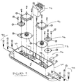
- Figure 2 shows an adsorption dryer which is an embodiment of the invention;
- Figure 3 is an upper valve manifold of the dryer of Figure 1;
- Figure 4 is a lower valve manifold of the dryer of Figure 1 shown inverted for clarity;
- Figure 5 shows an exhaust valve seat component which is part of the dryer of Figure 1;
- Figures 6 and 7 are sections through the valve of Figure 5 respectively in the direction of arrows A and B;
- Figure 8 is a section through part of a manifold, which shows the valve component of Figure 5; and
- Figure 9 is an exploded diagram of the manifold of Figure 3.
-
- Figure 1 shows a typical prior art adsorption dryer. The dryer comprises first and
second drying towers 10, 12 each containing desiccant material. Thetowers 10,12 are generally cylindrical and are disposed in an upright orientation. - Gas to be dried is received by an
inlet pipe 14 from where it is conveyed to thetowers 10,12 through aninlet system 16 of pipes and valves mounted above thetowers 10,12. Gas exiting from thetowers 10,12 is received by anoutlet system 18 of pipes and valves mounted below thetowers 10,12. - The inlet and
outlet systems valves 20 with either butt welded or threaded malleableiron interconnecting pipework 22. The systems include a large number of joints, each of which is a site of a potential leak and an obstacle to smooth gas flow, and each of which contributes to the labour involved in construction of the dryer. Operation of the valves is controlled by acontrol unit 24. - An embodiment of the invention is illustrated in Figures 2 to 9. For the purposes of this description, a heatless downflow dryer utilising diaphragm valves is used as an example. However, it will be realised that the invention is not restricted in application to dryers of this type.
- With reference now to Figure 2, a dryer embodying the invention comprises first and
second drying towers towers tower - An
inlet manifold 34 is connected to the upper ports of bothtowers outlet manifold 36 is connected to the lower ports of bothtowers - The two manifolds are constructed as around
identical castings 40. Various materials can be used for the casting ranging from Aluminium alloys to Spheroidal Graphite Iron to Polycarbonate composite plastics. Eachcasting 40 is symmetrical about a centre plane X between thetowers - Within each
casting 40 is formed fourvalve seats valve seats valve seats 42 are comparatively further from the plane X such that the other two of thevalve seats 44 are closer to the plane X. - Figures 5 to 7 show diagrammatically the
valve seats manifold 40. It should be understood that these figures show a portion of an integral casting. These are not separate components. - The valve seats 42 further from the plane X communicate with first, second and
third gas passages first gas passage 46 carries gas to the connection with the port of the correspondingtower second gas passage 48 carries gas to a first external connection point of the casting 40. Thethird gas passage 50 carries gasadjacent valve seat 44 closer to the plane X. - The two
valve seats 44 closer to the plane X each additionally communicate with one another through afourth gas passage 52. Aside branch 54 of thefourth gas passage 52 extends to carry gas to a central external connection point of the casting. - It must be borne in mind that the above-described arrangement appears symmetrically disposed to both sides of the plane X.
- Each of the
valve cylindrical valve chamber 58 within the casting. Eachchamber 58 has one open end, and the open end is surrounded by an annular first sealingsurface 60. - In the case of the valve seats 42 further from the plane X, the first and
third gas passages chamber 58 at respective radial openings. Thesecond gas passage 48 enters thechamber 58 within atubular formation 70 formed integrally with the casting 40. Thetubular formation 70 enters thechamber 58 radially, in a direction at right angles to the first and thethird gas passages chanter 58. An end surface of the tubular formation forms an annularsecond sealing surface 62 concentric with, and spaced axially into thechanter 58 from, thefirst sealing surface 60. - In the case of the valve seats 44 closer to the plane X, the
fourth gas passage 52 enters thechamber 58 at a radial opening. Thethird gas passage 50 enters thechanter 58 within atubular formation 68 formed integrally with the casting. Thetubular formation 68 enters thechanter 58 radially, in a direction diametrically opposite to thethird gas passage 50, and then turns through a bend of 90° such that an end portion of it is concentric with thechanter 58. An end surface of the tubular formation forms an annularsecond sealing surface 62 concentric with, and spaced axially into thechanter 58 from, thefirst sealing surface 60. - In both of the valve seats 42,44 described in the last two preceding paragraphs four tapped bores 66 are formed in the casting spaced around the
first sealing surface 60. These bores 66 can receivefasteners 90 to secure avalve actuator 72 or another component can be secured in place on the casting 40 to form a valve or some other component to control flow of gas within the manifold. - Where a valve is to be constructed on a
valve seat actuator 72 is determined by the function that the valve is to perform. In each case, in the present embodiment, theactuator 72 includes adiaphragm 92 under acap 94 which is sealed against thefirst sealing surface 60 and which can be urged against thesecond sealing surface 62 to close the port connected thereto. Thediaphragm 92 may be operated by a solenoid or under pneumatic control, as is convenient or it may be self-actuating. - In this embodiment, the
inlet manifold 34 includes two types of valve. Those valves V3, V4 constructed on valve seats further from the plane X are three portedbypass 2/2 exhaust valves. Theactuator 72 in this case comprises a pneumatically operated diaphragm. When the valve V3,V4 is open, gas can flow between the first, second andthird gas passages second gas passage 48. Closure of the valve V3,V4 does not prevent flow around the tubular formation between the first and thethird gas passages - Valves V1 and V2, which are two-ported 2/2 inlet valves, are constructed on the valve seats 44 closer to the plane X of the
inlet manifold 34. Theactuator 72 for these valves comprises a pneumatically operated diaphragm. When these valves V1,V2 are open, gas can flow between the third and thefourth gas passages - A
respective silencer inlet manifold 34. The central external connection point of theinlet manifold 34 receives a supply of gas to be dried. - A
control unit 96 for controlling operation of the dryer is mounted centrally on theinlet manifold 34. - In the
outlet manifold 36, the first external connection points are blocked. This may be done either with a plug inserted into them, or the connection points may simply not be drilled during manufacture of the casting 40. The central connection point provides an exit for dried gas. - On the
outlet manifold 36, the valve seats 42 further from the plane X are not used to construct valves as such. Rather, arespective cap 74 is secured to each of them byfasteners 90 to form a seal with thefirst sealing surface 60. Thecap 74 has a drilling through it into which a pipe fitting 76 is secured. A pipe 78 is connected between thepipe fittings 76 of both of the valve seats 42 further from the plane X. Thepipe fittings 76 have a flow passage to permit gas to flow from within thechamber 58 of thevalve seat 42 into thepipe 76. Within the drilling, there is formed a flow-restricting orifice which serves to restrict the rate of flow of gas through the drilling. - On the
outlet manifold 36, valves V5 and V6 are constructed on the valve seats 44 closer to the plane X. These valves are self-actuating check valves which permit gas to flow through them in one direction only: that is, in a direction from thethird gas passage 50 into thefourth gas passage 52. - In operation, suppose initially that the
first tower 30 is being used to dry the incoming gas and thesecond tower 32 is being regenerated having been saturated on the preceding drying cycle. Valve V1 would be open and valve V2 would be closed, thus directing the incoming gas stream through thefirst tower 30. To prevent the incoming gas from escaping through thefirst silencer 80, valve V3 remains closed. - Meanwhile, valve V4 is open, so that the
second tower 32 can depressurise through thesecond silencer 82. The check valve V6 is closed, preventing flow towards thesecond tower 32 of the gas stream exiting thefirst tower 30. The check valve V5 allows the dried gas stream to exit through the central external connection of theoutlet manifold 36 to the outlet. - A small bleed of purge gas is taken from the gas stream exiting the
first tower 30. The purge gas is bled from the dried gas stream through thepipe 76. The purge gas will, of course, also have passed through the orifice in each of the pipe fittings, expanding as it does so, the result being that its pressure is reduced from typically 7 barg and 35°C to substantially atmospheric pressure. The purge gas then passes through thesecond tower 32 stripping the adsorbed moisture from the bed, and then passes through valve V4 and out via thesecond silencer 82. - When the purge gas has desorbed the moisture from the
second tower 32, the valve V4 is closed to allow thesecond tower 32 to repressurise via thepipe 76. When thesecond tower 32 has reached its operating pressure, the valve V2 is opened and the valve V1 is closed to then direct the incoming gas stream through thesecond tower 32. - In order to regenerate the first tower 30 (which has been saturated) the valve V3 is opened so that the
first tower 30 can depressurise through thefirst silencer 80. The check valve V5 is closed and the check valve V6 is opened to allow the dried gas stream to exit via the outlet. Once again a small bleed of purge gas is passed through the pipe 76 (but in the reverse direction) to pass through thefirst tower 30 stripping the adsorbed moisture from the bed before passing through the valve V3 and out via thefirst silencer 80. - When the purge gas has desorbed the moisture from the
first tower 30, the valve V3 is closed, and thefirst tower 30 repressurises via thepipe 76. When thefirst tower 30 reaches its operating pressure and thesecond tower 32 has become saturated, the valves V1 and V2 switch once again, The entire cycle repeats continuously. - Various energy management systems are available and can be applied to dryers embodying the invention, such as that described in Patent Application No. 9602198.5.
- For large dryers, the valves V1, V2, V5 and V6 can use a duplex configuration in which two small valve mechanisms work in parallel to provide a means for a higher flowrate. In this configuration, two or more
tubular formations 68, each cooperate with arespective actuator 72 orcap 74 within acommon chamber 58. This configuration has several advantages over use of a single large valve. It increases usage of small valve parts thereby cutting purchase costs, tooling costs and inventory costs. It also reduce the casting size.
Claims (11)
- An adsorption dryer characterised by a first and a second drying tower (30,32) each having a first port and a second port through which gas can pass into or out of the tower; a first and a second manifold (34,36) connected respectively to the first and the second ports of both towers (30,32), the manifolds (34,36) each including integral gas passages (46, 48, 50, 52) each port of the towers (30,32) being in communication with a gas passage, and the manifolds (34,36) each including at least one integral valve seat upon which a valve actuator (72) is mounted to constitute a valve (V1..V6) for controlling flow of gas through the gas passages.
- An adsorption dryer according to claim 1 in which at least one of the valves (V1,V2) is a 3-port 2/2 valve which, in an open condition, permits passage of gas between all three of its ports and which, in a second condition, inhibits flow of gas through one of its ports while allowing passage of gas between the other two of its ports.
- An adsorption dryer according to claim 2 in which an exhaust valve of the dryer is a 3-port 2/2 valve.
- An adsorption dryer according to any preceding claim in which one of the manifolds (34) is an inlet manifold and the other of the manifolds (36) is an outlet manifold.
- An adsorption dryer according to any preceding claim in which each manifold (34, 36) is constructed on a respective casting or moulding.
- An adsorption dryer according to any preceding claim in which on at least one of the manifolds (36) there is provided a permanently-open interconnection path between the towers (10, 12) to provide a path for gas to flow directly therebetween.
- An adsorption dryer accordingly to claim 6 in which the interconnection path includes at least one orifice to restrict the flow of gas between the towers.
- An adsorption dryer according to claim 6 or claim 7 in which the interconnection path includes a pipe (76) external of the manifold (36).
- An adsorption dryer according to claim 8 in which the pipe (76) is connected at each of its ends to a cap secured to a respective one of the valve seats.
- An adsorption dryer according to any preceding claim in which inlet valves (V1, V2) are disposed on the inlet manifold (36) between the exhaust valves (V3, V4).
- An adsorption dryer according to claim 10 in which all of the valve seats (40) are formed on the casting between the first and second ports.
Priority Applications (3)
| Application Number | Priority Date | Filing Date | Title |
|---|---|---|---|
| GB9621039A GB2318150B (en) | 1996-10-09 | 1996-10-09 | Adsorption gas dryer two stage silencers with integral bypass |
| US09/084,085 US6036754A (en) | 1996-10-09 | 1998-05-26 | Adsorption gas dryer |
| EP98304188A EP0960646A1 (en) | 1996-10-09 | 1998-05-27 | Adsorption gas dryer |
Applications Claiming Priority (3)
| Application Number | Priority Date | Filing Date | Title |
|---|---|---|---|
| GB9621039A GB2318150B (en) | 1996-10-09 | 1996-10-09 | Adsorption gas dryer two stage silencers with integral bypass |
| US09/084,085 US6036754A (en) | 1996-10-09 | 1998-05-26 | Adsorption gas dryer |
| EP98304188A EP0960646A1 (en) | 1996-10-09 | 1998-05-27 | Adsorption gas dryer |
Publications (1)
| Publication Number | Publication Date |
|---|---|
| EP0960646A1 true EP0960646A1 (en) | 1999-12-01 |
Family
ID=27239531
Family Applications (1)
| Application Number | Title | Priority Date | Filing Date |
|---|---|---|---|
| EP98304188A Withdrawn EP0960646A1 (en) | 1996-10-09 | 1998-05-27 | Adsorption gas dryer |
Country Status (3)
| Country | Link |
|---|---|
| US (1) | US6036754A (en) |
| EP (1) | EP0960646A1 (en) |
| GB (1) | GB2318150B (en) |
Cited By (2)
| Publication number | Priority date | Publication date | Assignee | Title |
|---|---|---|---|---|
| EP1378286A2 (en) * | 2002-07-05 | 2004-01-07 | Walker Filtration Limited | Adsorption gas dryer |
| CN102151462A (en) * | 2011-02-28 | 2011-08-17 | 珠海市海夫实业发展有限公司 | Heatless regeneration adsorption-type compressed air drier |
Families Citing this family (15)
| Publication number | Priority date | Publication date | Assignee | Title |
|---|---|---|---|---|
| EP0949408B1 (en) * | 1998-04-09 | 2003-01-08 | Brian Walker | Silencer assembly for pressurised gases |
| US6755895B2 (en) * | 2002-04-09 | 2004-06-29 | H2Gen Innovations, Inc. | Method and apparatus for pressure swing adsorption |
| JP4398736B2 (en) * | 2002-04-24 | 2010-01-13 | エアーセップ・コーポレーション | Low noise oxygen concentrator |
| US20040258792A1 (en) * | 2003-06-23 | 2004-12-23 | Mold-Masters Limited | Injection molding manifold having a heating system with two portions |
| US6918953B2 (en) * | 2003-07-09 | 2005-07-19 | H2Gen Innovations, Inc. | Modular pressure swing adsorption process and apparatus |
| US20050072426A1 (en) * | 2003-10-07 | 2005-04-07 | Deane Geoffrey Frank | Portable gas fractionalization system |
| US7066985B2 (en) * | 2003-10-07 | 2006-06-27 | Inogen, Inc. | Portable gas fractionalization system |
| US20050072423A1 (en) * | 2003-10-07 | 2005-04-07 | Deane Geoffrey Frank | Portable gas fractionalization system |
| US7135059B2 (en) * | 2003-10-07 | 2006-11-14 | Inogen, Inc. | Portable gas fractionalization system |
| WO2005035037A2 (en) | 2003-10-07 | 2005-04-21 | Inogen, Inc. | Portable gas fractionalization system |
| US7637989B2 (en) * | 2003-12-31 | 2009-12-29 | Merits Health Products Co., Ltd. | Rapid cycle pressure swing adsorption oxygen concentration method and mechanical valve for the same |
| EP2537573A1 (en) * | 2004-10-12 | 2012-12-26 | Airsep Corporation | Mini-portable oxygen concentrator |
| US7686870B1 (en) | 2005-12-29 | 2010-03-30 | Inogen, Inc. | Expandable product rate portable gas fractionalization system |
| US9375679B2 (en) * | 2013-08-30 | 2016-06-28 | Haldex Brake Products Corporation | Air dryer assembly with manifold system |
| JP6466008B1 (en) * | 2018-03-22 | 2019-02-06 | レール・リキード−ソシエテ・アノニム・プール・レテュード・エ・レクスプロワタシオン・デ・プロセデ・ジョルジュ・クロード | Adsorption tower switching device |
Citations (5)
| Publication number | Priority date | Publication date | Assignee | Title |
|---|---|---|---|---|
| DE1963876A1 (en) * | 1969-12-20 | 1971-07-15 | Graeff Roderich Wilhelm | Selective molecule adsorption chambers for - gases and liquids |
| US4512781A (en) * | 1983-11-14 | 1985-04-23 | Pittsburgh Brass Manufacturing Company | Shuttle valves and system for fluid control |
| EP0172003A1 (en) * | 1984-08-13 | 1986-02-19 | Pall Corporation | Sorbing apparatus |
| GB2199513A (en) * | 1987-01-09 | 1988-07-13 | Jan Pieter Warnar | Device for continuous drying of a gas |
| WO1997017126A1 (en) * | 1995-11-07 | 1997-05-15 | Psl Pressurisation Equipment Limited | Apparatus for supplying dry air |
Family Cites Families (4)
| Publication number | Priority date | Publication date | Assignee | Title |
|---|---|---|---|---|
| FR87613E (en) * | 1964-11-05 | 1966-04-15 | Berliet Automobiles | Device for cleaning the exhaust gases of heat engines containing solid components |
| US4097248A (en) * | 1974-05-15 | 1978-06-27 | Graham-White Sales Corporation | Method for decontaminating compressed gas |
| GB8306825D0 (en) * | 1983-03-11 | 1983-04-20 | Bendix Ltd | Noise reducing device |
| WO1997005368A1 (en) * | 1995-06-30 | 1997-02-13 | Antoine Poppe | Filter for exhaust gases of a gasoline engine, respectively a diesel engine |
-
1996
- 1996-10-09 GB GB9621039A patent/GB2318150B/en not_active Expired - Fee Related
-
1998
- 1998-05-26 US US09/084,085 patent/US6036754A/en not_active Expired - Fee Related
- 1998-05-27 EP EP98304188A patent/EP0960646A1/en not_active Withdrawn
Patent Citations (5)
| Publication number | Priority date | Publication date | Assignee | Title |
|---|---|---|---|---|
| DE1963876A1 (en) * | 1969-12-20 | 1971-07-15 | Graeff Roderich Wilhelm | Selective molecule adsorption chambers for - gases and liquids |
| US4512781A (en) * | 1983-11-14 | 1985-04-23 | Pittsburgh Brass Manufacturing Company | Shuttle valves and system for fluid control |
| EP0172003A1 (en) * | 1984-08-13 | 1986-02-19 | Pall Corporation | Sorbing apparatus |
| GB2199513A (en) * | 1987-01-09 | 1988-07-13 | Jan Pieter Warnar | Device for continuous drying of a gas |
| WO1997017126A1 (en) * | 1995-11-07 | 1997-05-15 | Psl Pressurisation Equipment Limited | Apparatus for supplying dry air |
Cited By (3)
| Publication number | Priority date | Publication date | Assignee | Title |
|---|---|---|---|---|
| EP1378286A2 (en) * | 2002-07-05 | 2004-01-07 | Walker Filtration Limited | Adsorption gas dryer |
| EP1378286A3 (en) * | 2002-07-05 | 2004-03-03 | Walker Filtration Limited | Adsorption gas dryer |
| CN102151462A (en) * | 2011-02-28 | 2011-08-17 | 珠海市海夫实业发展有限公司 | Heatless regeneration adsorption-type compressed air drier |
Also Published As
| Publication number | Publication date |
|---|---|
| GB2318150B (en) | 2000-02-16 |
| GB9621039D0 (en) | 1996-11-27 |
| US6036754A (en) | 2000-03-14 |
| GB2318150A (en) | 1998-04-15 |
Similar Documents
| Publication | Publication Date | Title |
|---|---|---|
| US6036754A (en) | Adsorption gas dryer | |
| US6953498B2 (en) | Adsorption gas dryer | |
| KR102194968B1 (en) | Devices and systems for related swing adsorption processes | |
| EP1509312B1 (en) | Method and apparatus for pressure swing adsorption | |
| US7691183B2 (en) | Method for drying compressed gas and device used thereby | |
| JP4800308B2 (en) | Improved compression device | |
| CA2622261C (en) | Device for drying compressed gas | |
| JP2009508679A5 (en) | ||
| EP1171221B1 (en) | Spool valve for switching air flows between two adsorption beds | |
| CA2267013A1 (en) | Switching valve for multi-chamber adsorbent air and gas fractionation system | |
| GB2319585A (en) | Adsorption gas dryer with cast manifold and integral valving | |
| US6336278B1 (en) | Method and system for controlling airflow in a multiple bed desiccant drying system | |
| WO1999026034A1 (en) | Method and system for controlling airflow in a multiple bed desiccant drying system | |
| JPS61192324A (en) | Apparatus for dehumidifying compressed gas | |
| JP2000042347A (en) | Adsorption column and air dehumidifying device | |
| JPWO2021229314A5 (en) | ||
| JPS63274431A (en) | Pressure swing type gaseous mixture separation apparatus | |
| JPS61171524A (en) | Method and apparatus for dehumidifying compressed air | |
| MXPA00004878A (en) | Method and system for controlling airflow in a multiple bed desiccant drying system |
Legal Events
| Date | Code | Title | Description |
|---|---|---|---|
| PUAI | Public reference made under article 153(3) epc to a published international application that has entered the european phase |
Free format text: ORIGINAL CODE: 0009012 |
|
| AK | Designated contracting states |
Kind code of ref document: A1 Designated state(s): DE DK FR GB IT NL |
|
| AX | Request for extension of the european patent |
Free format text: AL;LT;LV;MK;RO;SI |
|
| 17P | Request for examination filed |
Effective date: 19991227 |
|
| AKX | Designation fees paid |
Free format text: DE DK FR GB IT NL |
|
| 17Q | First examination report despatched |
Effective date: 20030606 |
|
| STAA | Information on the status of an ep patent application or granted ep patent |
Free format text: STATUS: THE APPLICATION IS DEEMED TO BE WITHDRAWN |
|
| 18D | Application deemed to be withdrawn |
Effective date: 20031217 |