EP0960576A1 - Rod transfer apparatus - Google Patents
Rod transfer apparatus Download PDFInfo
- Publication number
- EP0960576A1 EP0960576A1 EP98304186A EP98304186A EP0960576A1 EP 0960576 A1 EP0960576 A1 EP 0960576A1 EP 98304186 A EP98304186 A EP 98304186A EP 98304186 A EP98304186 A EP 98304186A EP 0960576 A1 EP0960576 A1 EP 0960576A1
- Authority
- EP
- European Patent Office
- Prior art keywords
- suction
- kicker
- rod
- housing
- rods
- Prior art date
- Legal status (The legal status is an assumption and is not a legal conclusion. Google has not performed a legal analysis and makes no representation as to the accuracy of the status listed.)
- Granted
Links
- 230000002093 peripheral effect Effects 0.000 claims abstract 8
Images



Classifications
-
- A—HUMAN NECESSITIES
- A24—TOBACCO; CIGARS; CIGARETTES; SIMULATED SMOKING DEVICES; SMOKERS' REQUISITES
- A24C—MACHINES FOR MAKING CIGARS OR CIGARETTES
- A24C5/00—Making cigarettes; Making tipping materials for, or attaching filters or mouthpieces to, cigars or cigarettes
- A24C5/32—Separating, ordering, counting or examining cigarettes; Regulating the feeding of tobacco according to rod or cigarette condition
- A24C5/322—Transporting cigarettes during manufacturing
- A24C5/326—Transporting cigarettes during manufacturing with lateral transferring means
Definitions
- This invention relates to a rod transfer apparatus. More specifically it is concerned with a kicker apparatus for removing tobacco rods or filters from a manufacturing line.
- Kickers are well known and have been used for many years, for example to pick finished tobacco rods off a rod maker and to pass them to a transfer which in turn passes them to a filter tipper.
- Known kickers include in-line or straight kickers which accelerate the rod in the line of the vee-rail of the rod maker on which they are formed, and helical kickers which insert a lateral component into the movement of the rod.
- the invention aims to provide an improved kicker which can present double length rods to a transfer apparatus without the rod being damaged.
- the invention resides in the provision of air to a rod on the kicker to break the suction holding the rod to the kicker and so ensure release of the rod at the correct time.
- a kicker assembly for picking rods off a rod making apparatus and accelerating it to a rod receiving station, the assembly comprising: a suction housing having a suction passageway extending from its peripheral wall, and a rod release passageway extending from its peripheral wall; a kicker wheel having a flange having a plurality of holes, the kicker wheel being mounted for rotation around the suction housing such that the holes pass over the suction passageway and the rod release passageway; wherein the rod release passageway is adjacent the suction passageway and behind the suction passage such that the kicker wheel first picks rods by suction applied through the suction passageway and then releases rods through air applied through the rod passageway; and a drive for rotating the kicker wheel.
- the invention further provides a kicker assembly for picking rods from the rod making apparatus and accelerating them to a rod receiving station comprising:
- Embodiments of the invention may have the advantage that air blown through the rod release passageway detaches rods from the kicker and breaks any residual suction enabling the rod to be released at the correct attitude for entry onto a receiving station such as a fluted drum. Consequently the risk of damage to the rod during transfer is diminished.
- the suction to the rods is cut off as the air is applied to release the rods.
- the holes in the flange may be circular or elongate, in the form of through-slots.
- the suction housing further comprises a suction reservoir, the suction passageway extending between the suction reservoir and the peripheral wall of the housing.
- the reservoir and the suction housing ensures a constant suction is applied to the rods and counters the effect of the passageway repeatedly opening and closing as the holes in the kicker wheel pass over. This has the advantage that the assembly is capable of holding heavier rods and so is suitable for double length rods.
- the transfer apparatus 10 of figures 1 and 2 is an example of the apparatus with which the kicker embodying the present invention could be used an is not to be construed as limiting.
- Tobacco rods 12 are formed as double length on a rod maker (now shown).
- the finished rods are transported on the vee-rail 14 of the rod maker to the kicker 20 which picks the rods off the rail and transfers them to the receiving drum 30 of the transfer apparatus.
- the receiving drum has a cover 40 and receives rods from the kicker at high speed.
- the rods are received in flutes on the drum and decelerated and held by a series of suction holes along the length of the flutes.
- the flutes have flared ends to make it easier for the rods to be received from the kicker in the flutes.
- Rods are picked from the receiving drum on to an intermediate drum 50 and then picked onto a cutting drum 60 where the rods are split into two single lengths. From there the rods are passed two a separating drum 70 which moves the individual rods of each pair apart and thence to a filter assembly drum 80 which inserts a double length filter between the separated rods. The filters are then joined to the rods and cut to form individual cigarettes in a conventional tipper such as the Hauni-Korber AG Max series tipper (not shown).
- a conventional tipper such as the Hauni-Korber AG Max series tipper (not shown).
- the kicker assembly comprises a main housing 100 which is mounted on the rod maker.
- a drive 110 which is driven from the rod maker drive via a shaft at the far end of the housing (not shown) through a timex pulley and belt (not shown).
- the drive transfers drive via a drive belt 112 to a kicker shaft 114, Both the drive shaft and the kicker shaft have toothed belt wheels 116 on which the drive belt is mounted.
- the belt 112 is retained inside a belt housing 118 to which is fixed a suction housing 120.
- the belt housing is pivotable about the drive 110 to set the kicker wheel at the correct height above the rod maker vee-rail. Attached to the belt housing is a bar 117 to which is fixed a guide plate 119.
- the suction housing is shown in figures 8 to 10 and comprises a solid flange having a central aperture 122 and a hub 124 which is connected to the belt housing.
- a suction passage 126 is formed in the periphery of the flange at a position between the central axis of the flange and the front face.
- the suction passageway passes through the flange to a suction reservoir 128 at the rear of the flange.
- the reservoir 128 is provided to ensure a constant suction as will be described.
- the reservoir 128 is connected to a suction pump (not shown).
- This passageway 129 is a rod release passageway and is connected to an air supply (not shown) at the rear of the flange, the rod release passage way 129 passing through the flange approximately parallel to the suction passageway.
- the air supply pushes air through the rod release passage way to break the suction applied by the suction passageway to release rods from the kicker.
- a kicker wheel 130 Over the suction flange, which is static, is arranged a kicker wheel 130.
- the kicker wheel comprises a front face 132, a peripheral flange 134 and a hub 136.
- the hub passes through the central aperture 122 of the suction flange and is fixed to the kicker shaft 114 for rotation therewith.
- the peripheral flange is not continuous but divided into two sections of equal length by two relieved areas 138.
- Each flange section has a groove 140 running along its length with a series of equally spaced holes 142 formed at the base of the groove. In the figures the holes are shown as bing circular but they could equally well be elongate in the form of slots extending through the flange.
- the grooves are arranged off the centre of the flange such that they overlie the suction and rod release passageways of the suction flange, and such that when mounted on the housing, the grooves overlie the centreline 150 (fig 3) of tobacco rods on the vee-rail of the rod maker.
- the kicker wheel 130 rotates above the rods on the vee-rail.
- the suction provided through the holes in the grooves picks individual rods from the rail and the rotation of the kicker wheel accelerates the rods towards the receiving drum.
- the reservoir in the suction flange ensures that the suction is maintained.
- the suction is effectively being switched on and off as the holes pass over the suction aperture.
- the reservoir mitagates against a loss of suction which might cause a rod to be released from the kicker. This is particularly important with double length rods whose increased weight requires a greater suction.
- a rod will be released from the kicker when a relieved portion on the kicker periphery, where there are no holes or slots, passes over the suction passageway cutting off the suction and releasing the rods.
- the clearance between the flutes of the receiving drum 30 and its cover 40 is small and a raised tip could be damaged by the cover or, in the worst case, be prevented from entering the receiving drum causing the whole manufacturing line to break down.
- the air blown through the rod release passageway ensures that any residual suction is broken and that the tip of the rod is exactly parallel with the receiving drum flutes when it is released. This ensures that the rod is successfully transferred from the vee-rail to the receiving drum.
- modified kicker described may be used with high speed double length rod makers enabling the advantages of low cost, simple kickers to be retained and obviating the need for complex, expensive transfer apparatus such as spiders.
- the kicker described is a straight, in-line kicker the invention is equally applicable to any other kicker such as a helical kicker which inserts a lateral component to the rod as it is being transformed.
Landscapes
- Manufacturing Of Cigar And Cigarette Tobacco (AREA)
- Nozzles For Electric Vacuum Cleaners (AREA)
- Hooks, Suction Cups, And Attachment By Adhesive Means (AREA)
Abstract

Description
- This invention relates to a rod transfer apparatus. More specifically it is concerned with a kicker apparatus for removing tobacco rods or filters from a manufacturing line.
- Kickers are well known and have been used for many years, for example to pick finished tobacco rods off a rod maker and to pass them to a transfer which in turn passes them to a filter tipper. Known kickers include in-line or straight kickers which accelerate the rod in the line of the vee-rail of the rod maker on which they are formed, and helical kickers which insert a lateral component into the movement of the rod.
- Modern tobacco rod makers increase production speeds by making rods as double lengths which are cut into single lengths after the transfer apparatus. Kickers have been found to be unsuitable for use with double length rods as they have a tendency to present the rods to the receiving drum of the transfer apparatus at an attitude slightly inclined to the horizontal, as a result of which the tip of the rod can foul against the corner of the receiving drum damaging the rod or inhibiting transfer. This might not matter if filter rods were being transferred as filters are more robust than tobacco rods and eventually wrapped with tipping paper concealing any damage. It is not however acceptable for tobacco rods. This has led to kickers being abandoned for double length rod makers in favour of much more complex apparatus such as the Spider made by Hauni-Korber AG of Germany. In contrast to the Hauni-Korber Spider, kickers are simple, cheap and easy to manufacture. It would be desirable to use kickers for transferring double length rods.
- The invention aims to provide an improved kicker which can present double length rods to a transfer apparatus without the rod being damaged.
- In its broadest form the invention resides in the provision of air to a rod on the kicker to break the suction holding the rod to the kicker and so ensure release of the rod at the correct time.
- More specifically there is provided a kicker assembly for picking rods off a rod making apparatus and accelerating it to a rod receiving station, the assembly comprising: a suction housing having a suction passageway extending from its peripheral wall, and a rod release passageway extending from its peripheral wall; a kicker wheel having a flange having a plurality of holes, the kicker wheel being mounted for rotation around the suction housing such that the holes pass over the suction passageway and the rod release passageway; wherein the rod release passageway is adjacent the suction passageway and behind the suction passage such that the kicker wheel first picks rods by suction applied through the suction passageway and then releases rods through air applied through the rod passageway; and a drive for rotating the kicker wheel.
- The invention further provides a kicker assembly for picking rods from the rod making apparatus and accelerating them to a rod receiving station comprising:
- a drive housing for attachment to the rod making apparatus;
- drive means received in the housing and having at least one rotatable shaft;
- a suction housing coupled to the housing, the suction housing having a peripheral wall having a first port connected to a suction apparatus and a second port connected to an air supply; and
- a kicker wheel coupled to the shaft for rotation therewith, the kicker wheel having a peripheral flange arranged around the peripheral wall of the suction housing for rotation thereabout, and having a plurality of holes positioned to pass over the first and second ports of the suction housing on rotation, each hole passing first over the first port for picking rods from the rod making apparatus and then over the second part for releasing rods to the rod receiving station.
-
- Embodiments of the invention may have the advantage that air blown through the rod release passageway detaches rods from the kicker and breaks any residual suction enabling the rod to be released at the correct attitude for entry onto a receiving station such as a fluted drum. Consequently the risk of damage to the rod during transfer is diminished.
- Preferably, the suction to the rods is cut off as the air is applied to release the rods.
- The holes in the flange may be circular or elongate, in the form of through-slots.
- Preferably the suction housing further comprises a suction reservoir, the suction passageway extending between the suction reservoir and the peripheral wall of the housing.
- The reservoir and the suction housing ensures a constant suction is applied to the rods and counters the effect of the passageway repeatedly opening and closing as the holes in the kicker wheel pass over. This has the advantage that the assembly is capable of holding heavier rods and so is suitable for double length rods.
- An embodiment of the invention will now be described, by way of example only, and with reference to the accompanying drawings, in which:
- Figure 1 is a perspective view of a transfer apparatus including a kicker embodying the invention;
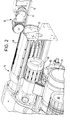
- Figure 2 is an enlarged view of a portion of the apparatus of figure 1;
- Figure 3 is a plan off a kicker assembly embodying the present invention;
- Figure 4 is a front view of the assembly of figure 3 with the housing cover removed;
- Figure 5 is a plan of the kicker wheel;
- Figure 6 is a front view of the kicker wheel;
- Figure 7 is a section on the line A-A in Figure 6;
- Figure 8 is a plan of the suction housing;
- Figure 9 is front view of the suction housing; and
- Figure 10 is a rear view of the suction housing.
-
- The
transfer apparatus 10 of figures 1 and 2 is an example of the apparatus with which the kicker embodying the present invention could be used an is not to be construed as limiting. - Tobacco
rods 12 are formed as double length on a rod maker (now shown). The finished rods are transported on the vee-rail 14 of the rod maker to thekicker 20 which picks the rods off the rail and transfers them to the receivingdrum 30 of the transfer apparatus. - The receiving drum has a
cover 40 and receives rods from the kicker at high speed. The rods are received in flutes on the drum and decelerated and held by a series of suction holes along the length of the flutes. The flutes have flared ends to make it easier for the rods to be received from the kicker in the flutes. - Rods are picked from the receiving drum on to an
intermediate drum 50 and then picked onto acutting drum 60 where the rods are split into two single lengths. From there the rods are passed two a separatingdrum 70 which moves the individual rods of each pair apart and thence to afilter assembly drum 80 which inserts a double length filter between the separated rods. The filters are then joined to the rods and cut to form individual cigarettes in a conventional tipper such as the Hauni-Korber AG Max series tipper (not shown). - The kicker assembly comprises a
main housing 100 which is mounted on the rod maker. At an end of the housing is adrive 110 which is driven from the rod maker drive via a shaft at the far end of the housing (not shown) through a timex pulley and belt (not shown). The drive transfers drive via adrive belt 112 to akicker shaft 114, Both the drive shaft and the kicker shaft have toothedbelt wheels 116 on which the drive belt is mounted. Thebelt 112 is retained inside abelt housing 118 to which is fixed asuction housing 120. The belt housing is pivotable about thedrive 110 to set the kicker wheel at the correct height above the rod maker vee-rail. Attached to the belt housing is abar 117 to which is fixed aguide plate 119. The guide plate is held above the vee-rail behind the kicker wheel and prevents the trailing ends of rods flicking up as the leading edge is picked up by the kicker wheel. It also acts to keep the rods in line. The suction housing is shown in figures 8 to 10 and comprises a solid flange having acentral aperture 122 and ahub 124 which is connected to the belt housing. Asuction passage 126 is formed in the periphery of the flange at a position between the central axis of the flange and the front face. The suction passageway passes through the flange to asuction reservoir 128 at the rear of the flange. Thereservoir 128 is provided to ensure a constant suction as will be described. Thereservoir 128 is connected to a suction pump (not shown). - At a position adjacent and slightly behind the suction aperture (in the direction of rod movement) is a
second passageway 129. Thispassageway 129 is a rod release passageway and is connected to an air supply (not shown) at the rear of the flange, the rodrelease passage way 129 passing through the flange approximately parallel to the suction passageway. The air supply pushes air through the rod release passage way to break the suction applied by the suction passageway to release rods from the kicker. - Over the suction flange, which is static, is arranged a
kicker wheel 130. The kicker wheel comprises afront face 132, aperipheral flange 134 and ahub 136. The hub passes through thecentral aperture 122 of the suction flange and is fixed to thekicker shaft 114 for rotation therewith. The peripheral flange is not continuous but divided into two sections of equal length by tworelieved areas 138. Each flange section has agroove 140 running along its length with a series of equally spacedholes 142 formed at the base of the groove. In the figures the holes are shown as bing circular but they could equally well be elongate in the form of slots extending through the flange. The grooves are arranged off the centre of the flange such that they overlie the suction and rod release passageways of the suction flange, and such that when mounted on the housing, the grooves overlie the centreline 150 (fig 3) of tobacco rods on the vee-rail of the rod maker. - In use, the
kicker wheel 130 rotates above the rods on the vee-rail. The suction provided through the holes in the grooves picks individual rods from the rail and the rotation of the kicker wheel accelerates the rods towards the receiving drum. The reservoir in the suction flange ensures that the suction is maintained. As the suction is communicated through holes in the groove, the suction is effectively being switched on and off as the holes pass over the suction aperture. The reservoir mitagates against a loss of suction which might cause a rod to be released from the kicker. This is particularly important with double length rods whose increased weight requires a greater suction. - A rod will be released from the kicker when a relieved portion on the kicker periphery, where there are no holes or slots, passes over the suction passageway cutting off the suction and releasing the rods. However, there is a tendency for there to be some residual suction which can lift the tip of the rod. As can be seen from figures 1 and 2, the clearance between the flutes of the receiving
drum 30 and itscover 40 is small and a raised tip could be damaged by the cover or, in the worst case, be prevented from entering the receiving drum causing the whole manufacturing line to break down. - The air blown through the rod release passageway ensures that any residual suction is broken and that the tip of the rod is exactly parallel with the receiving drum flutes when it is released. This ensures that the rod is successfully transferred from the vee-rail to the receiving drum.
- Thus the modified kicker described may be used with high speed double length rod makers enabling the advantages of low cost, simple kickers to be retained and obviating the need for complex, expensive transfer apparatus such as spiders.
- Although the kicker described is a straight, in-line kicker the invention is equally applicable to any other kicker such as a helical kicker which inserts a lateral component to the rod as it is being transformed.
Claims (12)
- A kicker assembly for picking rods off a rod making apparatus and accelerating it to a rod receiving station, the assembly comprising:a suction housing having a suction passageway extending from its peripheral wall, and a rod release passageway extending from its periphery;a kicker wheel having a flange having a plurality of holes, the kicker wheel being mounted for rotation around the suction housing such that the holes pass over the suction passageway and the rod release passageway; whereinthe rod release passageway is adjacent the suction passageway and behind the suction passage such that the kicker wheel first picks rods by suction applied through the suction passageway and then releases rods through air applied through the rod passageway; anda drive for rotating the kicker wheel.
- A kicker assembly according to claim 1, wherein the flange of the kicker wheel is shaped to cut off suction to the rod as air is applied through the rod release passageway.
- A kicker assembly according to claim 1 or 2, wherein the suction housing further comprises a suction reservoir, the suction passageway extending between the suction reservoir and the peripheral wall of the housing.
- A kicker assembly according to claim 1, 2 or 3, wherein the suction passageway and the rod release passageway are parallel to one another.
- A kicker assembly according to any preceding claim wherein the holes in the kicker wheel flange are formed in the groove in the flange.
- A kicker assembly according to claim 5, wherein the groove is divided into first and second portions separated by a pair of relieved areas.
- A kicker assembly according to any preceding claim, wherein the suction passageway allows the rod release passageway extend from points on the periphery of the suction housing between the central axis of the peripheral wall and an edge of the peripheral wall.
- A kicker assembly according to any preceding claim wherein the drive is mounted in a drive housing and the function housing is coupled to the drive housing.
- A kicker assembly according to any preceding claim wherein the kicker wheel is a straight kicker wheel which accelerates rods in the direction of rod travel along the rod maker with substantially no lateral component.
- A kicker assembly according to claim 1 to 8, wherein the kicker wheel is a helical kicker wheel which accelerates rods in the direction of rod travel along the rod maker with a lateral component.
- A kicker assembly for picking rods of rod making apparatus and accelerating them to a rod receiving station comprising:a drive housing for attachment to the rod making apparatus;drive means received in the housing and having at least one rotatable shaft;a suction housing coupled to the housing, the suction housing having a peripheral wall having a first port connected to a suction apparatus and a second port connected to an air supply; anda kicker wheel coupled to the shaft for rotation therewith, the kicker wheel having a peripheral flange arranged around the peripheral wall of the suction housing for rotation thereabout, and having a plurality of holes positioned to pass over the first and second ports of the suction housing on rotation, each hole passing first over the first port for picking rods from the rod making apparatus and then over the second part for releasing rods to the rod receiving station.
- A kicker assembly according to any preceding claim, wherein the holes in the flange of the kicker wheel are elongate slots.
Priority Applications (6)
| Application Number | Priority Date | Filing Date | Title |
|---|---|---|---|
| DE69810446T DE69810446T2 (en) | 1998-05-27 | 1998-05-27 | Device for transferring rod-shaped articles |
| AT98304186T ATE230221T1 (en) | 1998-05-27 | 1998-05-27 | DEVICE FOR TRANSFERRING BAR-SHAPED ARTICLES |
| EP98304186A EP0960576B1 (en) | 1998-05-27 | 1998-05-27 | Rod transfer apparatus |
| AU28473/99A AU2847399A (en) | 1998-05-27 | 1999-03-16 | Rod transfer apparatus |
| PCT/GB1999/000795 WO1999060873A1 (en) | 1998-05-27 | 1999-03-16 | Rod transfer apparatus |
| ARP990101967A AR015032A1 (en) | 1998-05-27 | 1999-04-28 | A LAUNCH ASSEMBLY TO TAKE AND REMOVE THE VARITAS OUTSIDE OF AN APPLIANCE THAT CONNECTS |
Applications Claiming Priority (1)
| Application Number | Priority Date | Filing Date | Title |
|---|---|---|---|
| EP98304186A EP0960576B1 (en) | 1998-05-27 | 1998-05-27 | Rod transfer apparatus |
Publications (2)
| Publication Number | Publication Date |
|---|---|
| EP0960576A1 true EP0960576A1 (en) | 1999-12-01 |
| EP0960576B1 EP0960576B1 (en) | 2003-01-02 |
Family
ID=8234851
Family Applications (1)
| Application Number | Title | Priority Date | Filing Date |
|---|---|---|---|
| EP98304186A Expired - Lifetime EP0960576B1 (en) | 1998-05-27 | 1998-05-27 | Rod transfer apparatus |
Country Status (6)
| Country | Link |
|---|---|
| EP (1) | EP0960576B1 (en) |
| AR (1) | AR015032A1 (en) |
| AT (1) | ATE230221T1 (en) |
| AU (1) | AU2847399A (en) |
| DE (1) | DE69810446T2 (en) |
| WO (1) | WO1999060873A1 (en) |
Cited By (1)
| Publication number | Priority date | Publication date | Assignee | Title |
|---|---|---|---|---|
| EP1935260A1 (en) | 2006-12-20 | 2008-06-25 | Hauni Maschinenbau Aktiengesellschaft | Stabiliser for mechanical handling |
Citations (4)
| Publication number | Priority date | Publication date | Assignee | Title |
|---|---|---|---|---|
| US3039589A (en) * | 1959-02-10 | 1962-06-19 | Molins Machine Co Ltd | Apparatus for receiving cigarettes from the cut-off of a continuous rod cigarette-making machine |
| DE3423570A1 (en) * | 1983-07-13 | 1985-01-24 | Hauni-Werke Körber & Co KG, 2050 Hamburg | Apparatus for transferring rod-shaped articles in the tobacco processing industry from an axial to a trans-axial conveying direction |
| GB2149642A (en) * | 1983-09-13 | 1985-06-19 | Molins Plc | Machines for imparting lateral movement to cigarettes |
| DE3603895C1 (en) * | 1986-02-05 | 1987-06-25 | Bat Cigarettenfab Gmbh | Accelerator on a machine in the tobacco processing industry |
-
1998
- 1998-05-27 DE DE69810446T patent/DE69810446T2/en not_active Expired - Fee Related
- 1998-05-27 EP EP98304186A patent/EP0960576B1/en not_active Expired - Lifetime
- 1998-05-27 AT AT98304186T patent/ATE230221T1/en not_active IP Right Cessation
-
1999
- 1999-03-16 WO PCT/GB1999/000795 patent/WO1999060873A1/en not_active Ceased
- 1999-03-16 AU AU28473/99A patent/AU2847399A/en not_active Abandoned
- 1999-04-28 AR ARP990101967A patent/AR015032A1/en not_active Application Discontinuation
Patent Citations (4)
| Publication number | Priority date | Publication date | Assignee | Title |
|---|---|---|---|---|
| US3039589A (en) * | 1959-02-10 | 1962-06-19 | Molins Machine Co Ltd | Apparatus for receiving cigarettes from the cut-off of a continuous rod cigarette-making machine |
| DE3423570A1 (en) * | 1983-07-13 | 1985-01-24 | Hauni-Werke Körber & Co KG, 2050 Hamburg | Apparatus for transferring rod-shaped articles in the tobacco processing industry from an axial to a trans-axial conveying direction |
| GB2149642A (en) * | 1983-09-13 | 1985-06-19 | Molins Plc | Machines for imparting lateral movement to cigarettes |
| DE3603895C1 (en) * | 1986-02-05 | 1987-06-25 | Bat Cigarettenfab Gmbh | Accelerator on a machine in the tobacco processing industry |
Cited By (1)
| Publication number | Priority date | Publication date | Assignee | Title |
|---|---|---|---|---|
| EP1935260A1 (en) | 2006-12-20 | 2008-06-25 | Hauni Maschinenbau Aktiengesellschaft | Stabiliser for mechanical handling |
Also Published As
| Publication number | Publication date |
|---|---|
| DE69810446D1 (en) | 2003-02-06 |
| DE69810446T2 (en) | 2003-10-02 |
| WO1999060873A1 (en) | 1999-12-02 |
| AU2847399A (en) | 1999-12-13 |
| AR015032A1 (en) | 2001-04-11 |
| EP0960576B1 (en) | 2003-01-02 |
| ATE230221T1 (en) | 2003-01-15 |
Similar Documents
| Publication | Publication Date | Title |
|---|---|---|
| KR101504386B1 (en) | Method of compiling groups of segments in a process of producing multisegment filters and apparatus for preparing and compiling segments in groups in a process of producing multisegment filters | |
| US6736257B2 (en) | Device and method for transferring articles in the tobacco-processing industry | |
| EP0960576B1 (en) | Rod transfer apparatus | |
| US3363632A (en) | Filter-tipped cigarette making machine | |
| US2988198A (en) | Cigarette turn around device | |
| CN101573053A (en) | Production of a tobacco rod with a hollow cylindrical tube extending therethrough | |
| JPH08256750A (en) | Apparatus for guiding out excess operational air from distributor in tobacco processing machine | |
| US3039590A (en) | Apparatus for receiving cigarettes or similar rod-like articles | |
| EP0966890B1 (en) | Transfer assembly for tobacco rods | |
| GB2170693A (en) | Manufacture of cigarettes from two tobaccos | |
| US3825105A (en) | Decelerator of cigarettes collected by a fluted drum | |
| JPH0656B2 (en) | Machines for producing cigarettes or other rod-shaped articles | |
| US6913023B2 (en) | Filter attaching apparatus | |
| JPS60118178A (en) | Apparatus for taking off excessive tobacco from tobacco stream | |
| EP0838163A1 (en) | Device for transferring cigarette portions from a dual-rod cigarette manufacturing machine to a filter assembly machine | |
| JP3126447B2 (en) | Bar-shaped article cutting and separating equipment | |
| JP3170222B2 (en) | Leaf-mogi equipment | |
| US4556072A (en) | Cigarette reversing apparatus | |
| EP0350757B1 (en) | Machine for manufacturing filter-tip cigarettes | |
| US4305409A (en) | Cigarette making machines | |
| US12004556B2 (en) | Conveyor and method of aligning rod-shaped articles | |
| CN101287385B (en) | A unit for transferring sticks of rod material used to manufacture tobacco products | |
| JPS6028185Y2 (en) | strawberry harvester | |
| CZ237898A3 (en) | Spinning unit of spindleless spinning machine | |
| GB2211067A (en) | Dividing tobacco streams |
Legal Events
| Date | Code | Title | Description |
|---|---|---|---|
| PUAI | Public reference made under article 153(3) epc to a published international application that has entered the european phase |
Free format text: ORIGINAL CODE: 0009012 |
|
| AK | Designated contracting states |
Kind code of ref document: A1 Designated state(s): AT BE CH CY DE DK ES FI FR GB GR IE IT LI LU MC NL PT SE |
|
| AX | Request for extension of the european patent |
Free format text: AL;LT;LV;MK;RO;SI |
|
| 17P | Request for examination filed |
Effective date: 20000601 |
|
| AKX | Designation fees paid |
Free format text: AT BE CH CY DE DK ES FI FR GB GR IE IT LI LU MC NL PT SE |
|
| AXX | Extension fees paid |
Free format text: AL PAYMENT 20000601;LT PAYMENT 20000601;LV PAYMENT 20000601;MK PAYMENT 20000601;RO PAYMENT 20000601;SI PAYMENT 20000601 |
|
| GRAG | Despatch of communication of intention to grant |
Free format text: ORIGINAL CODE: EPIDOS AGRA |
|
| GRAG | Despatch of communication of intention to grant |
Free format text: ORIGINAL CODE: EPIDOS AGRA |
|
| 17Q | First examination report despatched |
Effective date: 20020211 |
|
| GRAG | Despatch of communication of intention to grant |
Free format text: ORIGINAL CODE: EPIDOS AGRA |
|
| GRAH | Despatch of communication of intention to grant a patent |
Free format text: ORIGINAL CODE: EPIDOS IGRA |
|
| GRAH | Despatch of communication of intention to grant a patent |
Free format text: ORIGINAL CODE: EPIDOS IGRA |
|
| GRAA | (expected) grant |
Free format text: ORIGINAL CODE: 0009210 |
|
| AK | Designated contracting states |
Kind code of ref document: B1 Designated state(s): AT BE CH CY DE DK ES FI FR GB GR IE IT LI LU MC NL PT SE |
|
| AX | Request for extension of the european patent |
Free format text: AL PAYMENT 20000601;LT PAYMENT 20000601;LV PAYMENT 20000601;MK PAYMENT 20000601;RO PAYMENT 20000601;SI PAYMENT 20000601 |
|
| PG25 | Lapsed in a contracting state [announced via postgrant information from national office to epo] |
Ref country code: NL Free format text: LAPSE BECAUSE OF FAILURE TO SUBMIT A TRANSLATION OF THE DESCRIPTION OR TO PAY THE FEE WITHIN THE PRESCRIBED TIME-LIMIT Effective date: 20030102 Ref country code: GR Free format text: LAPSE BECAUSE OF FAILURE TO SUBMIT A TRANSLATION OF THE DESCRIPTION OR TO PAY THE FEE WITHIN THE PRESCRIBED TIME-LIMIT Effective date: 20030102 Ref country code: FI Free format text: LAPSE BECAUSE OF FAILURE TO SUBMIT A TRANSLATION OF THE DESCRIPTION OR TO PAY THE FEE WITHIN THE PRESCRIBED TIME-LIMIT Effective date: 20030102 Ref country code: BE Free format text: LAPSE BECAUSE OF FAILURE TO SUBMIT A TRANSLATION OF THE DESCRIPTION OR TO PAY THE FEE WITHIN THE PRESCRIBED TIME-LIMIT Effective date: 20030102 Ref country code: AT Free format text: LAPSE BECAUSE OF FAILURE TO SUBMIT A TRANSLATION OF THE DESCRIPTION OR TO PAY THE FEE WITHIN THE PRESCRIBED TIME-LIMIT Effective date: 20030102 |
|
| REF | Corresponds to: |
Ref document number: 230221 Country of ref document: AT Date of ref document: 20030115 Kind code of ref document: T |
|
| REG | Reference to a national code |
Ref country code: GB Ref legal event code: FG4D Free format text: 20030102 |
|
| REG | Reference to a national code |
Ref country code: CH Ref legal event code: EP |
|
| REG | Reference to a national code |
Ref country code: IE Ref legal event code: FG4D |
|
| REF | Corresponds to: |
Ref document number: 69810446 Country of ref document: DE Date of ref document: 20030206 Kind code of ref document: P |
|
| REG | Reference to a national code |
Ref country code: CH Ref legal event code: NV Representative=s name: BOVARD AG PATENTANWAELTE |
|
| PG25 | Lapsed in a contracting state [announced via postgrant information from national office to epo] |
Ref country code: SE Free format text: LAPSE BECAUSE OF FAILURE TO SUBMIT A TRANSLATION OF THE DESCRIPTION OR TO PAY THE FEE WITHIN THE PRESCRIBED TIME-LIMIT Effective date: 20030402 Ref country code: PT Free format text: LAPSE BECAUSE OF FAILURE TO SUBMIT A TRANSLATION OF THE DESCRIPTION OR TO PAY THE FEE WITHIN THE PRESCRIBED TIME-LIMIT Effective date: 20030402 Ref country code: DK Free format text: LAPSE BECAUSE OF FAILURE TO SUBMIT A TRANSLATION OF THE DESCRIPTION OR TO PAY THE FEE WITHIN THE PRESCRIBED TIME-LIMIT Effective date: 20030402 |
|
| PG25 | Lapsed in a contracting state [announced via postgrant information from national office to epo] |
Ref country code: LU Free format text: LAPSE BECAUSE OF NON-PAYMENT OF DUE FEES Effective date: 20030527 Ref country code: IE Free format text: LAPSE BECAUSE OF NON-PAYMENT OF DUE FEES Effective date: 20030527 Ref country code: CY Free format text: LAPSE BECAUSE OF FAILURE TO SUBMIT A TRANSLATION OF THE DESCRIPTION OR TO PAY THE FEE WITHIN THE PRESCRIBED TIME-LIMIT Effective date: 20030527 |
|
| PG25 | Lapsed in a contracting state [announced via postgrant information from national office to epo] |
Ref country code: MC Free format text: LAPSE BECAUSE OF NON-PAYMENT OF DUE FEES Effective date: 20030531 |
|
| LTIE | Lt: invalidation of european patent or patent extension |
Effective date: 20030102 |
|
| PG25 | Lapsed in a contracting state [announced via postgrant information from national office to epo] |
Ref country code: ES Free format text: LAPSE BECAUSE OF FAILURE TO SUBMIT A TRANSLATION OF THE DESCRIPTION OR TO PAY THE FEE WITHIN THE PRESCRIBED TIME-LIMIT Effective date: 20030730 |
|
| ET | Fr: translation filed | ||
| PLBE | No opposition filed within time limit |
Free format text: ORIGINAL CODE: 0009261 |
|
| STAA | Information on the status of an ep patent application or granted ep patent |
Free format text: STATUS: NO OPPOSITION FILED WITHIN TIME LIMIT |
|
| 26N | No opposition filed |
Effective date: 20031003 |
|
| REG | Reference to a national code |
Ref country code: IE Ref legal event code: MM4A |
|
| PGFP | Annual fee paid to national office [announced via postgrant information from national office to epo] |
Ref country code: FR Payment date: 20040408 Year of fee payment: 7 |
|
| PGFP | Annual fee paid to national office [announced via postgrant information from national office to epo] |
Ref country code: CH Payment date: 20040413 Year of fee payment: 7 |
|
| PGFP | Annual fee paid to national office [announced via postgrant information from national office to epo] |
Ref country code: GB Payment date: 20040415 Year of fee payment: 7 |
|
| PGFP | Annual fee paid to national office [announced via postgrant information from national office to epo] |
Ref country code: DE Payment date: 20040422 Year of fee payment: 7 |
|
| PG25 | Lapsed in a contracting state [announced via postgrant information from national office to epo] |
Ref country code: IT Free format text: LAPSE BECAUSE OF NON-PAYMENT OF DUE FEES Effective date: 20050527 Ref country code: GB Free format text: LAPSE BECAUSE OF NON-PAYMENT OF DUE FEES Effective date: 20050527 |
|
| PG25 | Lapsed in a contracting state [announced via postgrant information from national office to epo] |
Ref country code: LI Free format text: LAPSE BECAUSE OF NON-PAYMENT OF DUE FEES Effective date: 20050531 Ref country code: CH Free format text: LAPSE BECAUSE OF NON-PAYMENT OF DUE FEES Effective date: 20050531 |
|
| PG25 | Lapsed in a contracting state [announced via postgrant information from national office to epo] |
Ref country code: DE Free format text: LAPSE BECAUSE OF NON-PAYMENT OF DUE FEES Effective date: 20051201 |
|
| REG | Reference to a national code |
Ref country code: CH Ref legal event code: PL |
|
| GBPC | Gb: european patent ceased through non-payment of renewal fee |
Effective date: 20050527 |
|
| PG25 | Lapsed in a contracting state [announced via postgrant information from national office to epo] |
Ref country code: FR Free format text: LAPSE BECAUSE OF NON-PAYMENT OF DUE FEES Effective date: 20060131 |
|
| REG | Reference to a national code |
Ref country code: FR Ref legal event code: ST Effective date: 20060131 |