EP0959801B1 - Screw thread implant - Google Patents
Screw thread implant Download PDFInfo
- Publication number
- EP0959801B1 EP0959801B1 EP97903696A EP97903696A EP0959801B1 EP 0959801 B1 EP0959801 B1 EP 0959801B1 EP 97903696 A EP97903696 A EP 97903696A EP 97903696 A EP97903696 A EP 97903696A EP 0959801 B1 EP0959801 B1 EP 0959801B1
- Authority
- EP
- European Patent Office
- Prior art keywords
- thread
- radius
- flank
- max
- implant
- Prior art date
- Legal status (The legal status is an assumption and is not a legal conclusion. Google has not performed a legal analysis and makes no representation as to the accuracy of the status listed.)
- Expired - Lifetime
Links
Images


Classifications
-
- A—HUMAN NECESSITIES
- A61—MEDICAL OR VETERINARY SCIENCE; HYGIENE
- A61C—DENTISTRY; APPARATUS OR METHODS FOR ORAL OR DENTAL HYGIENE
- A61C8/00—Means to be fixed to the jaw-bone for consolidating natural teeth or for fixing dental prostheses thereon; Dental implants; Implanting tools
-
- A—HUMAN NECESSITIES
- A61—MEDICAL OR VETERINARY SCIENCE; HYGIENE
- A61B—DIAGNOSIS; SURGERY; IDENTIFICATION
- A61B17/00—Surgical instruments, devices or methods
- A61B17/56—Surgical instruments or methods for treatment of bones or joints; Devices specially adapted therefor
- A61B17/58—Surgical instruments or methods for treatment of bones or joints; Devices specially adapted therefor for osteosynthesis, e.g. bone plates, screws or setting implements
- A61B17/68—Internal fixation devices, including fasteners and spinal fixators, even if a part thereof projects from the skin
- A61B17/84—Fasteners therefor or fasteners being internal fixation devices
- A61B17/86—Pins or screws or threaded wires; nuts therefor
- A61B17/8625—Shanks, i.e. parts contacting bone tissue
-
- A—HUMAN NECESSITIES
- A61—MEDICAL OR VETERINARY SCIENCE; HYGIENE
- A61C—DENTISTRY; APPARATUS OR METHODS FOR ORAL OR DENTAL HYGIENE
- A61C8/00—Means to be fixed to the jaw-bone for consolidating natural teeth or for fixing dental prostheses thereon; Dental implants; Implanting tools
- A61C8/0018—Means to be fixed to the jaw-bone for consolidating natural teeth or for fixing dental prostheses thereon; Dental implants; Implanting tools characterised by the shape
- A61C8/0022—Self-screwing
-
- A—HUMAN NECESSITIES
- A61—MEDICAL OR VETERINARY SCIENCE; HYGIENE
- A61F—FILTERS IMPLANTABLE INTO BLOOD VESSELS; PROSTHESES; DEVICES PROVIDING PATENCY TO, OR PREVENTING COLLAPSING OF, TUBULAR STRUCTURES OF THE BODY, e.g. STENTS; ORTHOPAEDIC, NURSING OR CONTRACEPTIVE DEVICES; FOMENTATION; TREATMENT OR PROTECTION OF EYES OR EARS; BANDAGES, DRESSINGS OR ABSORBENT PADS; FIRST-AID KITS
- A61F2/00—Filters implantable into blood vessels; Prostheses, i.e. artificial substitutes or replacements for parts of the body; Appliances for connecting them with the body; Devices providing patency to, or preventing collapsing of, tubular structures of the body, e.g. stents
- A61F2/02—Prostheses implantable into the body
- A61F2/30—Joints
- A61F2002/30001—Additional features of subject-matter classified in A61F2/28, A61F2/30 and subgroups thereof
- A61F2002/30316—The prosthesis having different structural features at different locations within the same prosthesis; Connections between prosthetic parts; Special structural features of bone or joint prostheses not otherwise provided for
- A61F2002/30317—The prosthesis having different structural features at different locations within the same prosthesis
- A61F2002/30321—The prosthesis having different structural features at different locations within the same prosthesis differing in roughness
-
- A—HUMAN NECESSITIES
- A61—MEDICAL OR VETERINARY SCIENCE; HYGIENE
- A61F—FILTERS IMPLANTABLE INTO BLOOD VESSELS; PROSTHESES; DEVICES PROVIDING PATENCY TO, OR PREVENTING COLLAPSING OF, TUBULAR STRUCTURES OF THE BODY, e.g. STENTS; ORTHOPAEDIC, NURSING OR CONTRACEPTIVE DEVICES; FOMENTATION; TREATMENT OR PROTECTION OF EYES OR EARS; BANDAGES, DRESSINGS OR ABSORBENT PADS; FIRST-AID KITS
- A61F2/00—Filters implantable into blood vessels; Prostheses, i.e. artificial substitutes or replacements for parts of the body; Appliances for connecting them with the body; Devices providing patency to, or preventing collapsing of, tubular structures of the body, e.g. stents
- A61F2/02—Prostheses implantable into the body
- A61F2/30—Joints
- A61F2/30767—Special external or bone-contacting surface, e.g. coating for improving bone ingrowth
- A61F2/30771—Special external or bone-contacting surface, e.g. coating for improving bone ingrowth applied in original prostheses, e.g. holes or grooves
- A61F2002/3085—Special external or bone-contacting surface, e.g. coating for improving bone ingrowth applied in original prostheses, e.g. holes or grooves with a threaded, e.g. self-tapping, bone-engaging surface, e.g. external surface
-
- A—HUMAN NECESSITIES
- A61—MEDICAL OR VETERINARY SCIENCE; HYGIENE
- A61F—FILTERS IMPLANTABLE INTO BLOOD VESSELS; PROSTHESES; DEVICES PROVIDING PATENCY TO, OR PREVENTING COLLAPSING OF, TUBULAR STRUCTURES OF THE BODY, e.g. STENTS; ORTHOPAEDIC, NURSING OR CONTRACEPTIVE DEVICES; FOMENTATION; TREATMENT OR PROTECTION OF EYES OR EARS; BANDAGES, DRESSINGS OR ABSORBENT PADS; FIRST-AID KITS
- A61F2/00—Filters implantable into blood vessels; Prostheses, i.e. artificial substitutes or replacements for parts of the body; Appliances for connecting them with the body; Devices providing patency to, or preventing collapsing of, tubular structures of the body, e.g. stents
- A61F2/02—Prostheses implantable into the body
- A61F2/30—Joints
- A61F2/30767—Special external or bone-contacting surface, e.g. coating for improving bone ingrowth
- A61F2/30771—Special external or bone-contacting surface, e.g. coating for improving bone ingrowth applied in original prostheses, e.g. holes or grooves
- A61F2002/3085—Special external or bone-contacting surface, e.g. coating for improving bone ingrowth applied in original prostheses, e.g. holes or grooves with a threaded, e.g. self-tapping, bone-engaging surface, e.g. external surface
- A61F2002/30851—Multiple threadings
-
- A—HUMAN NECESSITIES
- A61—MEDICAL OR VETERINARY SCIENCE; HYGIENE
- A61F—FILTERS IMPLANTABLE INTO BLOOD VESSELS; PROSTHESES; DEVICES PROVIDING PATENCY TO, OR PREVENTING COLLAPSING OF, TUBULAR STRUCTURES OF THE BODY, e.g. STENTS; ORTHOPAEDIC, NURSING OR CONTRACEPTIVE DEVICES; FOMENTATION; TREATMENT OR PROTECTION OF EYES OR EARS; BANDAGES, DRESSINGS OR ABSORBENT PADS; FIRST-AID KITS
- A61F2250/00—Special features of prostheses classified in groups A61F2/00 - A61F2/26 or A61F2/82 or A61F9/00 or A61F11/00 or subgroups thereof
- A61F2250/0014—Special features of prostheses classified in groups A61F2/00 - A61F2/26 or A61F2/82 or A61F9/00 or A61F11/00 or subgroups thereof having different values of a given property or geometrical feature, e.g. mechanical property or material property, at different locations within the same prosthesis
- A61F2250/0025—Special features of prostheses classified in groups A61F2/00 - A61F2/26 or A61F2/82 or A61F9/00 or A61F11/00 or subgroups thereof having different values of a given property or geometrical feature, e.g. mechanical property or material property, at different locations within the same prosthesis differing in roughness
Definitions
- the present invention relates to implants for implantation into bone, in particular to dental implants, said implants being provided with threads or an oriented macroroughness.
- oriented macroroughness should be understood to comprise elongated beads which may be continuous or not, which may be oriented along the periphery of a cross-section of the implant or not.
- the oriented macroroughness should have a cross-section or profile specified in the way the thread profile will be defined below and in the appended claims.
- Bone implants are normally made of rigid material, mostly of titanium, which has been shown to have an affinity for bone tissue and which has an excellent biocompability. Bone implants often have a cylindrical, threaded shape and are screwed into bore-holes in the bone tissue which may be pre-tapped or not.
- titanium implants attain a close apposition with the bone tissue which sometimes is called osseointegration.
- Some factors determining the tissue response to a bone implant have been found to be the following: the biocompatibility of the implant material, the implant design, the implant surface, the status of the host bed, the surgical technique and the loading conditions.
- the implant design is concerned, a review of the dental implant literature reveals that implants of a large number of different shapes have been used in the past. It appears as if new implant designs to a great extent have been introduced and evaluated on a trial and error basis. As the reason for an implant failure is multi-factorial, a good design may have been discarded due to for example an improper surgical technique or improper loading conditions. Titanium screw-shaped dental implants were used early in the 1960's, those implants do not appear to have been a success; possibly due to the reasons mentioned above.
- Screw-shaped titanium dental implants dominate the market today.
- Several studies have addressing the relation between macroscopic design and holding power of screws in bone. By far most of them have been made within the orthopaedic discipline and have had an experimental approach. Pullout tests were carried out in the 1950's on dog femurs and tibias using vitallium bone screws with different thread profiles. It was observed that when pulling out a freshly inserted screw, the bone threads did not strip but the screw pulled out a small cone-shaped button of compact bone. Clinical experience shows that a bone plate and its screws are sometimes avulsed from bone. This avulsion is preceded by bone resorbtion. The opinion has been expressed that such a loss of holding power is caused by mechanical factors.
- WO-A- 9306786 describes an endosteal dental implant consisting in an asymmetrical frustoconical screw of which the leading thread flank is almost prependicular to the axis of the implant.
- the second flank is shallower, forming an angle of 30° to a line perpendicular to the axis.
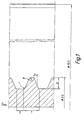
- Fig 1 illustrates how the parameters describing the profile according to the invention are defined.
- the implant shown is a screw-shaped dental implant with a diameter of 3.5 mm.
- the thread profile has two thread flanks and the height of the thread is D.
- the top radius formed at the apex of the thread profile at the intersection of the two thread flanks is designated R, and the bottom radius between two adjacent thread profiles r.
- the thread flanks form an angle v with a plane which is perpendicular to a cross-section of the thread and perpendicular to the surface of the implant body.
- the distance L is defined as the distance between the points of intersection between the two flanks on a thread and the surface of the implant body, the surface of the implant body being defined as the cylindrical surface touching the deepest parts of the threads.
- a standard prior art screw-shaped implant with an overall diameter of 3.5 mm would typically be provided with threads having a height D of about 0.35 mm, a flank angle v of 30°, a top radius R of about 0.065 mm corresponding to about 0.2xD and bottom radius of about 0.05 mm corresponding to about 0.15xD.
- the object of the invention is to equalize and mimimize the stress concentrations in the bone tissue which are a result of the loads on the implant in order to obtain an even stress distribution in the bone tissue so as to avoid resorption of the bone tissue because of high stress concentrations whilst avoiding low stresses that also might cause bone tissue resorption.
- screw threads either having a top radius exceeding 0.4xD or a flank angle exceeding 35° substantially equalizes the stress distribution in the bone tissue surrounding the implant.
- the top radius R should be larger than 0.2xD and smaller than D for 35° ⁇ v ⁇ 55° and 0.05 ⁇ D ⁇ 0.5 mm and larger than 0.4xD and smaller than D for 10° ⁇ v ⁇ 35° and 0.25 ⁇ D ⁇ 0.5 mm.
- the object studied is a vertically oriented screw-like implant with a major diameter of 3.5 mm.
- This implant is built up of identical axisymmetric elements where each element corresponds to one pitch height of a screw.
- the thread is modeled as a ring on each element.
- the profile of the thread as seen in Fig. 1 is characterized by the thread depth ( D ), the top radius ( R ), the flank angle ( v ), the bottom radius ( r ) and a straight part of the length S at the bottom of the thread.
- the length of the curved part of such an element is, as defined above, designated L .
- the bone was assumed to be attached to the inner wall of an outer cylinder with a diameter of 10.5 mm, see Fig. 1. Rotational symmetry was further assumed.
- the implant and the outer cylinder were assumed to be infinitely stiff while the bone was assumed to be a continuum material, isotropic and linearly elastic with a modulus of elasticity (Young's modulus) of 150 GPa and a Poisson's ratio amounting to 0.3.
- Youngng's modulus Youngng's modulus
- the bone-implant interface was frictionless and that only compressive forces could be transmitted between the implant and the bone.
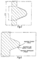
- These interface conditions are modeled by means of contact elements, the lines adjacent to the thread surface in Fig. 2. As is evident from fig. 2 parts of the interface does not have contact elements, the reason being that the interfacial bone at these locations in test runs had turned out to retreated from the implant.
- the load, F which was transmitted from the implant element into the bone tissue was set as a constant ( k ) multiplied with the length ( L + S ) of the implant element which latter was dependent upon the top radius, the flank angle, the bottom radius, the thread depth and the length of the straight part if any.
- the information seeked was the maximum tensile stress, the maximum compressive stress and the maximum von Mieses stress in the bone as a function of the values of the variables used.
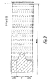
- the implant element was modeled to be completely stiff and fixed, the load F being applied at the further end of the bone as is shown in Fig. 3.
- the element mesh was built up parametrically.
- Each element contained four nodes, the number of degrees of freedom for each node being two.
- the number of elements used in the mesh varied with the length of the straight portion at the bottom of the thread expressed by the coefficient c. With a value of the coefficient c of 0, 0.2-0.4 and 0.8-1.6 the number of elements were 1129, 1305 and 1481 respectively.
- the ratios ⁇ u0 -/ ⁇ u0 + and ⁇ u90 -/ ⁇ u90 + are according to the above 1.45 and 2.61 respectively.
- the ratios ⁇ max -/1.45 and ⁇ max -/2.61 are presented in the results (tables 1-4 and 9-12).
- the ratio ⁇ max -/2 is the value which is of most interest.
- This formula does not take into consideration a situation where the compressive stress of a material differs from the tensile stress.
- An analysis of the results showed that the maximum von Mieses stress regularly was composed of one high compressive principal stress, one compressive stress of intermediate magnitude and one insignificant tensile principle stress. In order to be directly comparable with the maximum tensile stress the maximum von Mieses stress should, as the maximum compressive stress, be divided with a certain factor.
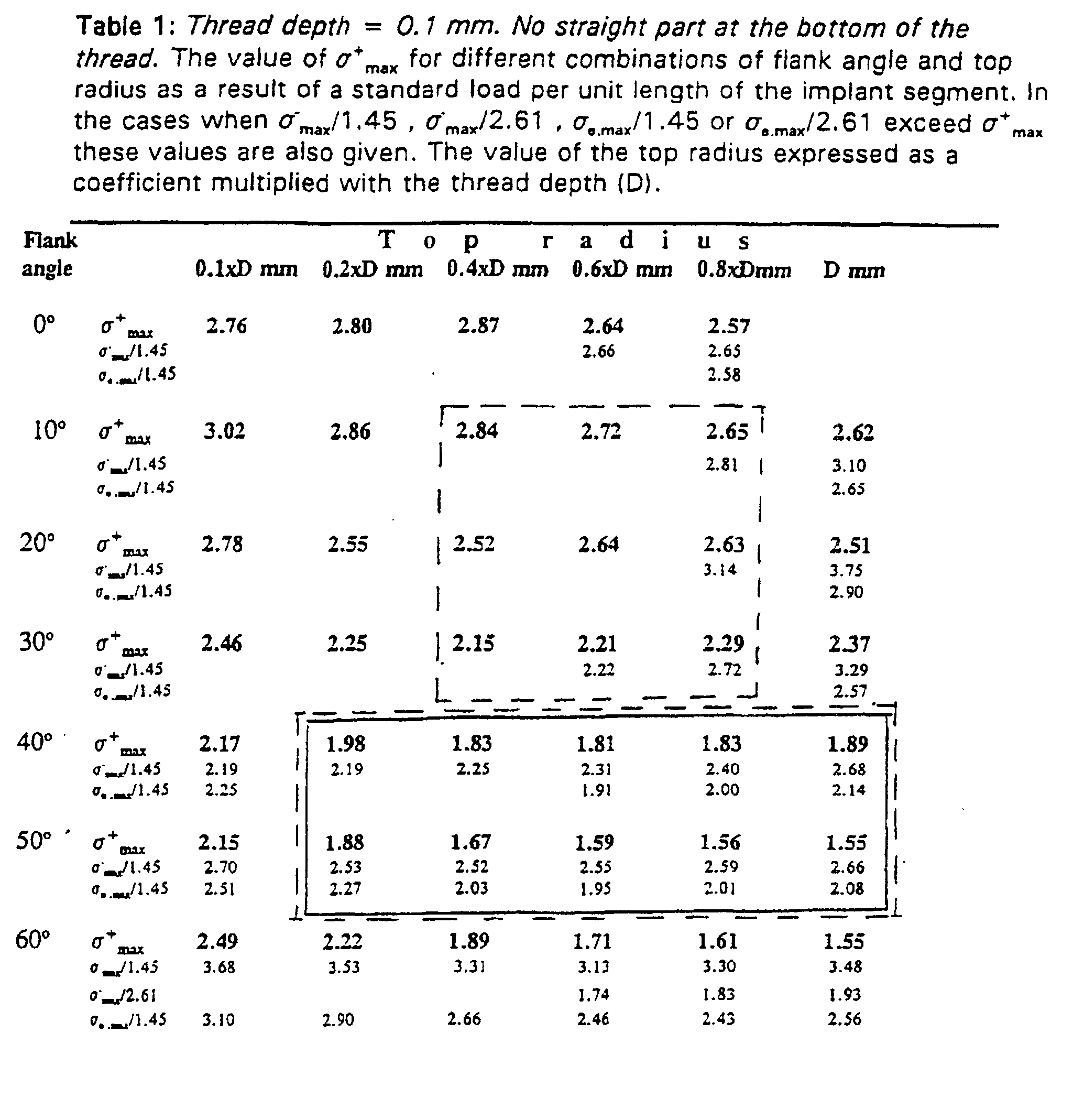
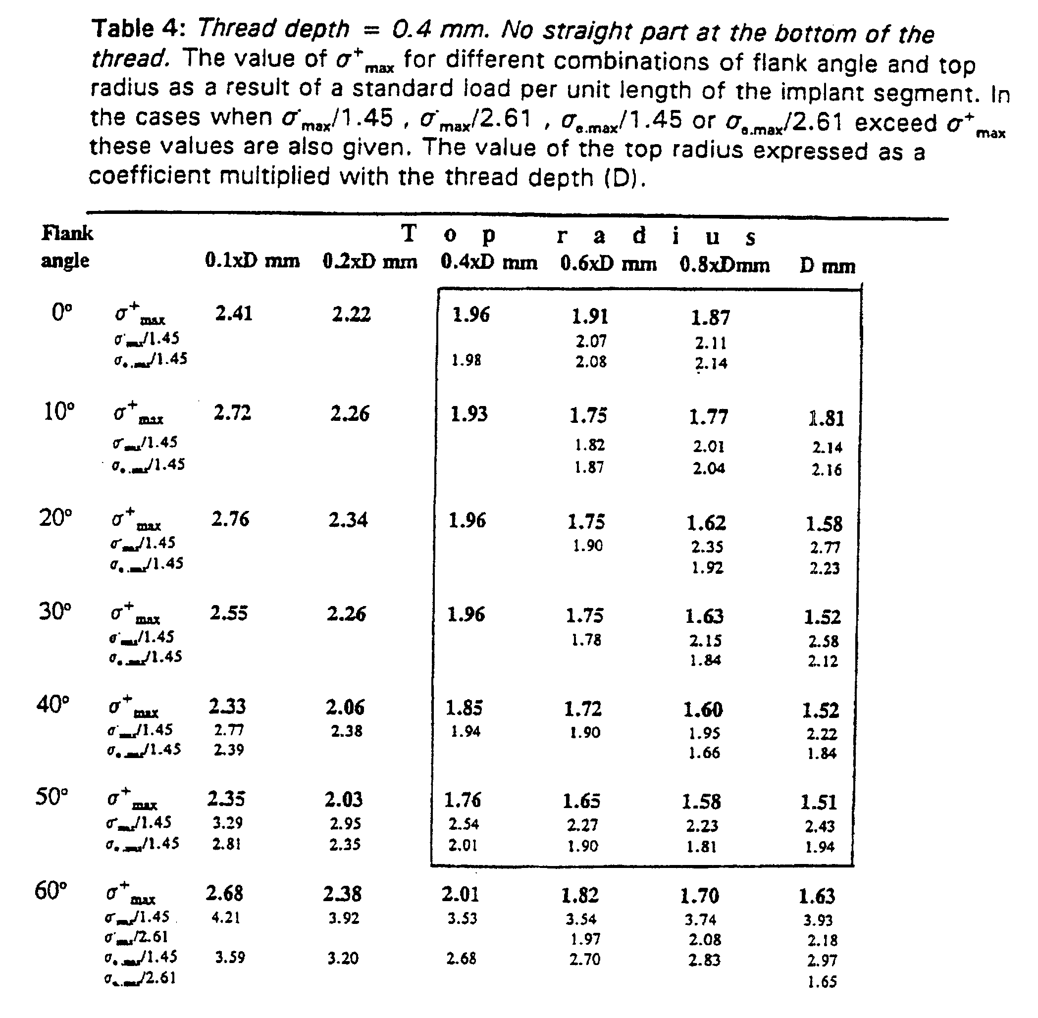
- Tables 1 - 4 show the results of the calculations.
- the values for ⁇ + max generally are less than 2 and for ⁇ max -/1.45 generally are less than 2.75 (which corresponds to a value also less than 2 for ⁇ max -/2) within the rectangles which are drawn with dashed lines in table 1 only but are to correspond to the fields 0.05 mm ⁇ D ⁇ 0.5 mm and 35° ⁇ v ⁇ 55°, the top radius R being larger than 0.2xD but smaller than D; 0.25 mm ⁇ D ⁇ 0.5 mm and 10° ⁇ v ⁇ 35°, R being greater than 0.4xD but smaller than D.
- the calculation results for the parameter fields in which ⁇ + max ⁇ 2 and ⁇ max -/2 ⁇ 2 are illustrated with full lines in the tables.
- Tables 5 - 8 illustrate the effect obtained by the introduction of a distance S between two adjacent threads.
- the part of the distance S which is staight is given as a coefficient to be multiplied with the length L, i. e. the distance defined above between the points where the flanks intersect the body of the implant. If the coefficient is 0 there is no positive effect of the introduction of a straight part.
- the positive effects mainly occur for small flank angles and for relatively large top radii, the parameter fields being shifted slighty to lower top radii for small flank angles as for instance can be seen by comparing tables 3 and 11.
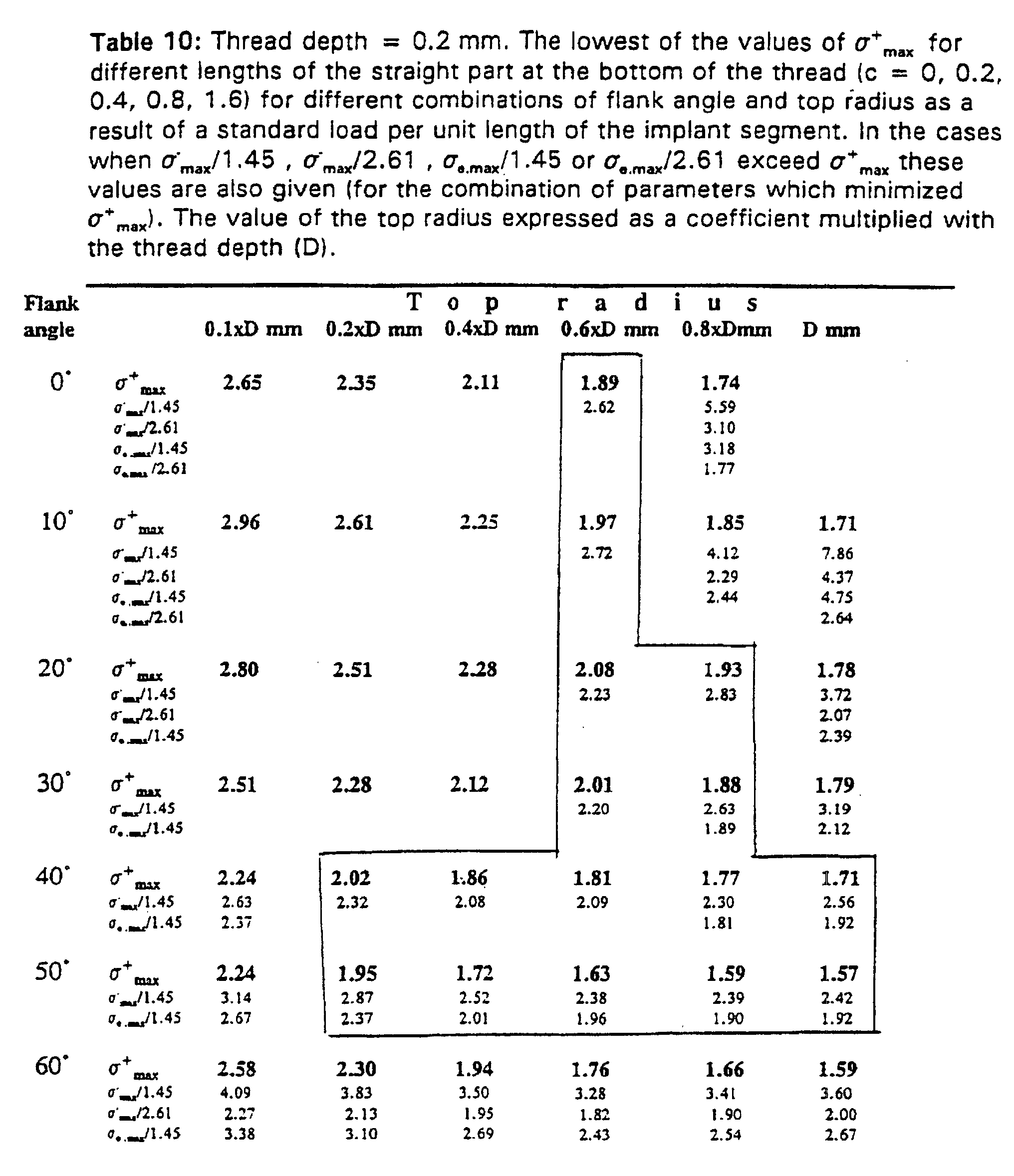
- Tables 9 - 12 show the minimum values for ⁇ + max and the corresponding ⁇ max -/1.45 corresponding to the values given in tables 5 - 8.
- Top radius Flank angle Bottom radius Thread height(D) Straight part at bottom 1 0.03-0.05 37°-43° 0.01-0.025 0.08-0.15 0 2 0.2D-1.0D 35°-55° 0 -0.2D 0.05-0.15 0 3 0.2D-1.0D 35°-55° 0 -0.2D 0.05-0.15 0-1D 4 0.2D-1.0D 35°-55° 0 -0.2D 0.05-0.15 1D-2D 5 0.2D-1.0D 35°-55° 0 -0.2D 0.15-0.25 0 6 0.2D-1.0D 35°-55° 0 -0.2D 0.15-0.25 0-1D 7 0.2D-1.0D 35°-55° 0 -0.2D 0.15-0.25 1D-2D 8 0.2D-1.0D 35°-55° 0 -0.2D 0.15-0.35 0 9 0.2D-1.0D 35°-55° 0 -0.2D 0.25-0.35 0 9 0.2D-1.0D 35
- the distance between adjacent threads is smaller than 3D, preferably smaller than 2D.
- the threads or macroroughness is combined with a microroughness having a pore size of 2 ⁇ to 20 ⁇ , preferably 2 ⁇ to 10 ⁇ .
- a microroughness having a pore size of 2 ⁇ to 20 ⁇ , preferably 2 ⁇ to 10 ⁇ .
- the radius R has been constant and has been real in the above examples.
- the top radius R at the apex is imaginary and defines a the transition point P1 between the straight flank and the curved apex, a first tangent through P1 being directed along said flank, as well as a crest point P2 on the apex in which a second tangent to the curved part is parallel to the longitudinal direction of the implant.
- the curved apex has the shape of curved part originating in said points P1 and P2 and has tangents in said points coinciding with said first and second tangents, and has a radius of curvature R1.
- the radius R1 may for instance increase from a value R min to a value R max or may increase from a value R min to a value R max , then decreasing to a value R min .
- R min should preferably be greater than 0.01 mm and the relationship R max /R min preferably should be greater than 3.
- flank angles of the thread or roughness not necessarily have to be identical even if this is a preferred embodiment. In some applications the angles may be different although both are within the ranges specified, in another applications it may be sufficient that the flank being the most heavily loaded has a flank angle within the ranges specified. The same is valid for the top radius which in similarity may have different values on the respective sides of the thread, both values or only one value being within the ranges specified.
Landscapes
- Health & Medical Sciences (AREA)
- Orthopedic Medicine & Surgery (AREA)
- Life Sciences & Earth Sciences (AREA)
- Animal Behavior & Ethology (AREA)
- Veterinary Medicine (AREA)
- Public Health (AREA)
- General Health & Medical Sciences (AREA)
- Surgery (AREA)
- Oral & Maxillofacial Surgery (AREA)
- Dentistry (AREA)
- Epidemiology (AREA)
- Medical Informatics (AREA)
- Molecular Biology (AREA)
- Heart & Thoracic Surgery (AREA)
- Biomedical Technology (AREA)
- Engineering & Computer Science (AREA)
- Nuclear Medicine, Radiotherapy & Molecular Imaging (AREA)
- Neurology (AREA)
- Prostheses (AREA)
- Dental Prosthetics (AREA)
- Materials For Medical Uses (AREA)
Description
- The present invention relates to implants for implantation into bone, in particular to dental implants, said implants being provided with threads or an oriented macroroughness. The term "oriented macroroughness" should be understood to comprise elongated beads which may be continuous or not, which may be oriented along the periphery of a cross-section of the implant or not. The oriented macroroughness should have a cross-section or profile specified in the way the thread profile will be defined below and in the appended claims.
- Bone implants are normally made of rigid material, mostly of titanium, which has been shown to have an affinity for bone tissue and which has an excellent biocompability. Bone implants often have a cylindrical, threaded shape and are screwed into bore-holes in the bone tissue which may be pre-tapped or not.
- Under certain conditions titanium implants attain a close apposition with the bone tissue which sometimes is called osseointegration. Some factors determining the tissue response to a bone implant have been found to be the following: the biocompatibility of the implant material, the implant design, the implant surface, the status of the host bed, the surgical technique and the loading conditions. As far as the implant design is concerned, a review of the dental implant literature reveals that implants of a large number of different shapes have been used in the past. It appears as if new implant designs to a great extent have been introduced and evaluated on a trial and error basis. As the reason for an implant failure is multi-factorial, a good design may have been discarded due to for example an improper surgical technique or improper loading conditions. Titanium screw-shaped dental implants were used early in the 1960's, those implants do not appear to have been a success; possibly due to the reasons mentioned above.
- Overloading has been identified as a main etiologic factor behind loss of dental implants today. If bone is subject to extreme stress it will be resorbed. Assuming that stress induced bone resorbtion is triggered off when the stresses reaches a certain level, an implant should have such a design that the maximum stresses arising in the bone, as a result of a certain load, is minimized.
- Screw-shaped titanium dental implants dominate the market today. Several studies have adressed the relation between macroscopic design and holding power of screws in bone. By far most of them have been made within the orthopaedic discipline and have had an experimental approach. Pullout tests were carried out in the 1950's on dog femurs and tibias using vitallium bone screws with different thread profiles. It was observed that when pulling out a freshly inserted screw, the bone threads did not strip but the screw pulled out a small cone-shaped button of compact bone. Clinical experience shows that a bone plate and its screws are sometimes avulsed from bone. This avulsion is preceded by bone resorbtion. The opinion has been expressed that such a loss of holding power is caused by mechanical factors. Continuous compression of cancellous bone by screw threads has been shown to result in hypertrophy and realignment of the trabeculae in parallell with the force. It has also been claimed that cortical bone subjected to compression retains its integrity and is not resorbed.
- The relevance of pull-out experiments can however be doubted. In a pull-out test acute fracture is provoked. Dental implants seldom fail by acute fracture of the supporting bone. On the contrary the fracture of the implant-bone interface is normally the end of a long process of marginal bone resorbtion. As mentioned above, the assumption that stress induced bone resorbtion is triggered off when the stresses reaches a certain level implies that an implant should be given such a design that the stress peaks arising in the bone are minimized.
- WO-A- 9306786 describes an endosteal dental implant consisting in an asymmetrical frustoconical screw of which the leading thread flank is almost prependicular to the axis of the implant. The second flank is shallower, forming an angle of 30° to a line perpendicular to the axis.
- It has been found that a bone implant being provided with threads or an oriented macro-roughness intended to transfer loads to the bone tissue and designed in accordance with the appended main claim minimizes the stress peaks in the surrounding bone tissue. Preferred embodiments are set forth in the dependent claims.
-
- Fig 1 illustrates a profile of a thread or roughness according to the invention;
- Fig 2 illustrates the so called contact elements on the profile;
- Fig 3 illustrates the model used to calculate the stresses;
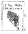
- Figs 4 and 5 show the distribution of the elements around the profile of a profile according to the invention respectively a prior art implant
- Fig 6 illustrates the location of the different maximal stresses.
- Fig 7 illstrates an alternative embodiment of the apex of the thread
-
- Fig 1 illustrates how the parameters describing the profile according to the invention are defined. The implant shown is a screw-shaped dental implant with a diameter of 3.5 mm.
- The thread profile has two thread flanks and the height of the thread is D. The top radius formed at the apex of the thread profile at the intersection of the two thread flanks is designated R, and the bottom radius between two adjacent thread profiles r. The thread flanks form an angle v with a plane which is perpendicular to a cross-section of the thread and perpendicular to the surface of the implant body. The distance L is defined as the distance between the points of intersection between the two flanks on a thread and the surface of the implant body, the surface of the implant body being defined as the cylindrical surface touching the deepest parts of the threads.
- A standard prior art screw-shaped implant with an overall diameter of 3.5 mm would typically be provided with threads having a height D of about 0.35 mm, a flank angle v of 30°, a top radius R of about 0.065 mm corresponding to about 0.2xD and bottom radius of about 0.05 mm corresponding to about 0.15xD.
- As discussed above, the object of the invention is to equalize and mimimize the stress concentrations in the bone tissue which are a result of the loads on the implant in order to obtain an even stress distribution in the bone tissue so as to avoid resorption of the bone tissue because of high stress concentrations whilst avoiding low stresses that also might cause bone tissue resorption.
- In accordance with the invention it has been found that screw threads (macro-roughness) either having a top radius exceeding 0.4xD or a flank angle exceeding 35° substantially equalizes the stress distribution in the bone tissue surrounding the implant. More particularly, the top radius R should be larger than 0.2xD and smaller than D for 35° ≤ v ≤ 55° and 0.05 ≤ D ≤ 0.5 mm and larger than 0.4xD and smaller than D for 10° ≤ v < 35° and 0.25 ≤ D ≤ 0.5 mm.
- An embodiment which at present seems most promising is an embodiment wherein 0.03 ≤ R ≤ 0.05 mm, 37° ≤ v ≤ 43°, 0.01 ≤ r ≤ 0.025 and 0.08 ≤ D ≤ 0.15.
- The following calculations illustrate this point. The calculations are performed by means of finite element analysis. The theory of elasticity according to Timoshenko is applied. The program used is Ansys revision 5.0.
- The object studied is a vertically oriented screw-like implant with a major diameter of 3.5 mm. This implant is built up of identical axisymmetric elements where each element corresponds to one pitch height of a screw. The thread is modeled as a ring on each element. The profile of the thread as seen in Fig. 1 is characterized by the thread depth ( D ), the top radius ( R ), the flank angle ( v ), the bottom radius ( r ) and a straight part of the length S at the bottom of the thread. The length of the curved part of such an element is, as defined above, designated L . The straight part of the length ( S ) was set as a coefficient c multiplied with this length ( S = c·L ). Calculations were made for values of the thread depth of 0.1 mm, 0.2 mm, 0.3 mm and 0.4 mm while the value of the top radius was set as a coefficient multiplied with the thread depth. The value of this coefficient was set at 0.1, 0.2, 0.4, 0.6, 0.8 and 1. The flank angle was varied between 0° and 60° with an increment of 10°. The bottom radius was set at 0.1 times the thread depth. The coefficient c was set at 0, 0.2, 0.4, 0.8 and 1.6. This means that a total of 4 x 6 x 7 x 5 x 1 = 840 different thread profiles are used. The implant was assumed to be infinitely long and was assumed to be completely embedded in cortical bone. 100% bone apposition was assumed. The bone was assumed to be attached to the inner wall of an outer cylinder with a diameter of 10.5 mm, see Fig. 1. Rotational symmetry was further assumed. The implant and the outer cylinder were assumed to be infinitely stiff while the bone was assumed to be a continuum material, isotropic and linearly elastic with a modulus of elasticity (Young's modulus) of 150 GPa and a Poisson's ratio amounting to 0.3. It was assumed that the bone-implant interface was frictionless and that only compressive forces could be transmitted between the implant and the bone. These interface conditions are modeled by means of contact elements, the lines adjacent to the thread surface in Fig. 2. As is evident from fig. 2 parts of the interface does not have contact elements, the reason being that the interfacial bone at these locations in test runs had turned out to retreated from the implant.
- An infinitely big axial load (a finite load per screw element) was applied on the infinitely long implant. With the assumptions made, the same mechanical events (stresses, strains, displacements) will occur in the bone outside all elements of which the infinitely long implant is composed. Consequently it is sufficient to study one single element of the implant, including the surrounding bone, provided that proper boundary conditions can be set up wherein this element with its surrounding bone borders to the overlying and underlying counterparts. The boundary conditions which were used were that, when the load was applied, all nodes in the bone lying in the horisontal plane defined by the upper limiting surface of the element in couples underwent the same displacements as the corresponding nodes in the bone lying in the horisontal plane defined by the lower limiting surface of the same element (Fig.3).
- The load, F , which was transmitted from the implant element into the bone tissue was set as a constant ( k ) multiplied with the length ( L + S ) of the implant element which latter was dependent upon the top radius, the flank angle, the bottom radius, the thread depth and the length of the straight part if any. The information seeked was the maximum tensile stress, the maximum compressive stress and the maximum von Mieses stress in the bone as a function of the values of the variables used. The implant element was modeled to be completely stiff and fixed, the load F being applied at the further end of the bone as is shown in Fig. 3.
- The element mesh was built up parametrically. In fig. 4 and 5 the element mesh close to the implant is shown for two calculation examples called Parameter set 1 and Parameter set 2. Parameter set 1 corresponds to a thread profile according to the invention with D = 0.1 mm, v = 40° and R = 0.4xD, r = 0.1xD whereas parameter set 2 largely corresponds to the prior art implant given above. Each element contained four nodes, the number of degrees of freedom for each node being two. The number of elements used in the mesh varied with the length of the straight portion at the bottom of the thread expressed by the coefficient c. With a value of the coefficient c of 0, 0.2-0.4 and 0.8-1.6 the number of elements were 1129, 1305 and 1481 respectively.
- It is assumed that the screw-like structure was embedded in cortical bone. The following mean values for the ultimate stress of human cortical bone have been obtained empirically: σu0 + = 133 MPa, σu0- = 193 MPa, σu90 + = 51 MPa and σu90 - = 133 MPa where the ultimate stress in regard of tension and compression is denoted by σu + and σu- respectively. σu0 and σu90 signify ultimate stresses in parallell with the long axis of the bone respectively in a transversal plane. It is natural to allow bone stresses of different kinds in proportion to the ultimate stress. The ratios σu0-/σu0 + and σu90-/σu90 + are according to the above 1.45 and 2.61 respectively. In order to simplify comparisons with the maximum tensile stresses obtained the ratios σmax-/1.45 and σmax-/2.61 are presented in the results (tables 1-4 and 9-12). However, for the calculations, the ratio σmax-/2 is the value which is of most interest.
- Disregarding the von Mieses stress, the combination of values of the profile parameters which minimizes the highest of the values, σ+ max and σmax-/2 may be regarded as the most favourable thread design.
- The von Mieses stress can be expressed by the formula
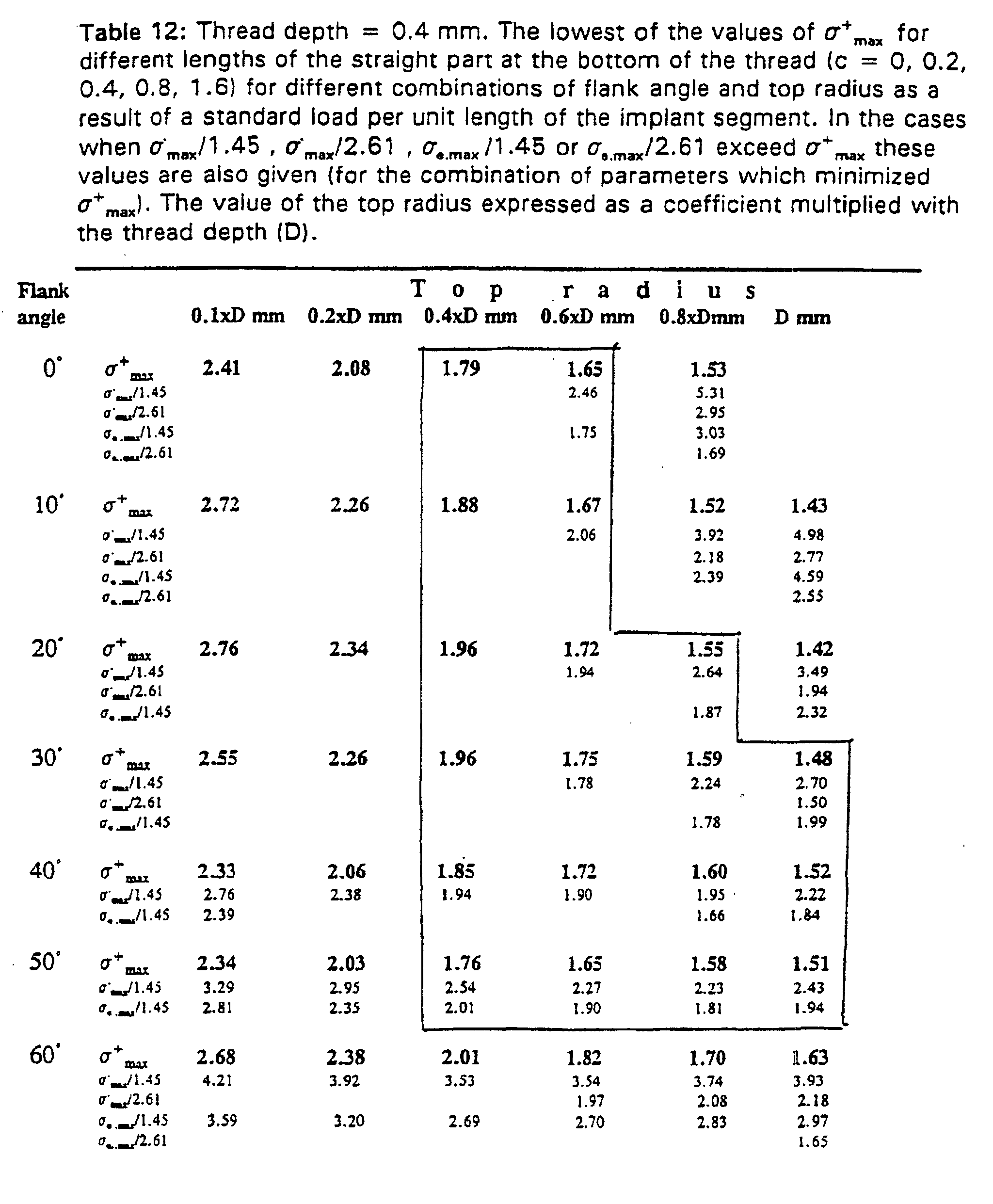
- Tables 1 - 4 show the results of the calculations. As can be seen in in the tables, the values for σ+ max generally are less than 2 and for σmax-/1.45 generally are less than 2.75 (which corresponds to a value also less than 2 for σmax-/2) within the rectangles which are drawn with dashed lines in table 1 only but are to correspond to the fields 0.05 mm ≤ D ≤ 0.5 mm and 35° ≤ v ≤ 55°, the top radius R being larger than 0.2xD but smaller than D; 0.25 mm ≤ D ≤ 0.5 mm and 10° ≤ v < 35°, R being greater than 0.4xD but smaller than D. The calculation results for the parameter fields in which σ+ max<2 and σmax-/2<2 are illustrated with full lines in the tables.
- As clearly can be seen, the standard screw-shaped implant falls outside these parameter fields.
- Tables 5 - 8 illustrate the effect obtained by the introduction of a distance S between two adjacent threads. The part of the distance S which is staight is given as a coefficient to be multiplied with the length L, i. e. the distance defined above between the points where the flanks intersect the body of the implant. If the coefficient is 0 there is no positive effect of the introduction of a straight part. As can be seen, the positive effects mainly occur for small flank angles and for relatively large top radii, the parameter fields being shifted slighty to lower top radii for small flank angles as for instance can be seen by comparing tables 3 and 11.
- Tables 9 - 12 show the minimum values for σ+ max and the corresponding σmax-/1.45 corresponding to the values given in tables 5 - 8.
- Some preferred embodiments are given in the following lists.
Top radius Flank angle Bottom radius Thread height(D) Straight part at bottom 1 0.03-0.05 37°-43° 0.01-0.025 0.08-0.15 0 2 0.2D-1.0D 35°-55° 0 -0.2D 0.05-0.15 0 3 0.2D-1.0D 35°-55° 0 -0.2D 0.05-0.15 0-1D 4 0.2D-1.0D 35°-55° 0 -0.2D 0.05-0.15 1D-2D 5 0.2D-1.0D 35°-55° 0 -0.2D 0.15-0.25 0 6 0.2D-1.0D 35°-55° 0 -0.2D 0.15-0.25 0-1D 7 0.2D-1.0D 35°-55° 0 -0.2D 0.15-0.25 1D-2D 8 0.2D-1.0D 35°-55° 0 -0.2D 0.25-0.35 0 9 0.2D-1.0D 35°-55° 0 -0.2D 0.25-0.35 0-1D 10 0.2D-1.0D 35°-55° 0 -0.2D 0.25-0.35 1D-2D 11 0.2D-1.0D 35°-55° 0 -0.2D 0.35-0.50 0 12 0.2D-1.0D 35°-55° 0 -0.2D 0.35-0.50 0-1D 13 0.2D-1.0D 35°-55° 0 -0.2D 0.35-0.50 1D-2D 14 0.2D-1.0D 35°-55° 0.2D-1.0D 0.05-0.15 0 15 0.2D-1.0D 35°-55° 0.2D-0.8D 0.05-0.15 0-1D 16 0.2D-1.0D 35°-55° 0.2D-0.6D 0.05-0.15 1D-2D 17 0.2D-1.0D 35°-55° 0.2D-1.0D 0.15-0.25 0 18 0.2D-1.0D 35°-55° 0.2D-0.8D 0.15-0.25 0-1D 19 0.2D-1.0D 35°-55° 0.2D-0.6D 0.15-0.25 1D-2D 20 0.2D-1.0D 35°-55° 0.2D-1.0D 0.25-0.35 0 21 0.2D-1.0D 35°-55° 0.2D-0.8D 0.25-0.35 0-1D 22 0.2D-1.0D 35°-55° 0.2D-0.6D 0.25-0.35 1D-2D 23 0.2D-1.0D 35°-55° 0.2D-1.0D 0.35-0.50 0 24 0.2D-1.0D 35°-55° 0.2D-0.8D 0.35-0.50 0-1D 25 0.2D-1.0D 35°-55° 0.2D-0.6D 0.35-0.50 1D-2D 26 0.2D-1.0D 35°-55° < 0.85R 0.05-0.15 0 27 0.2D-1.0D 35°-55° < 0.85R 0.05-0.15 0-1D 28 0.2D-1.0D 35°-55° < 0.85R 0.05-0.15 1D-2D 29 0.2D-1.0D 35°-55° < 0.85R 0.15-0.25 0 30 0.2D-1.0D 35°-55° < 0.85R 0.15-0.25 0-1D 31 0.2D-1.0D 35°-55° < 0.85R 0.15-0.25 1D-2D 32 0.2D-1.0D 35°-55° < 0.85R 0.25-0.35 0 33 0.2D-1.0D 35°-55° < 0.85R 0.25-0.35 0-1D 34 0.2D-1.0D 35°-55° < 0.85R 0.25-0.35 1D-2D 35 0.4D-0.6D 10°-35° 0 -0.6D 0.05-0.15 0 36 0.4D-0.6D 10°-35° 0 -0.6D 0.05-0.15 0-1D 37 0.4D-0.6D 10°-35° 0 -0.6D 0.05-0.15 1D-2D 38 0.4D-0.6D 10°-35° 0 -0.6D 0.15-0.25 0 39 0.4D-0.6D 10°-35° 0 -0.6D 0.15-0.25 0-1D 40 0.4D-0.6D 10°-35° 0 -0.6D 0.15-0.25 1D-2D 41 0.4D-0.6D 10°-35° 0 -0.6D 0.25-0.35 0 42 0.4D-0.6D 10°-35° 0 -0.6D 0.25-0.35 0-1D 43 0.4D-0.6D 10°-35° 0-0.6D 0.25-0.35 1D-2D 44 0.4D-0.6D 10°-35° 0 -0.6D 0.35-0.50 0 45 0.4D-0.6D 10°-35° 0 -0.6D 0.35-0.50 0-1D 46 0.4D-0.6D 10°-35° 0 -0.6D 0.35-0.50 1D-2D 47 0.4D-0.6D 10°-35° 0.6D-1D 0.05-0.15 0 48 0.4D-0.6D 10°-35° 0.6D-0.8D 0.05-0.15 0-1D 49 0.4D-0.6D 10°-35° 0.6D-1D 0.15-0.25 0 50 0.4D-0.6D 10°-35° 0.6D-0.8D 0.15-0.25 0-1D 51 0.4D-0.6D 10°-35° 0.6D-1D 0.25-0.35 0 52 0.4D-0.6D 10°-35° 0.6D-0.8D 0.25-0.35 0-1D 53 0.4D-0.6D 10°-35° 0.6D-1D 0.35-0.50 0 54 0.4D-0.6D 10°-35° 0.6D-0.8D 0.35-0.50 0-1D 55 0.6D-1D 10°-35° 0 -0.6D 0.05-0.15 0 56 0.6D-1D 10°-35° 0 -0.6D 0.05-0.15 0-1D 57 0.6D-1D 10°-35° 0 -0.6D 0.05-0.15 1D-2D 58 0.6D-1D 10°-35° 0 -0.6D 0.15-0.25 0 59 0.6D-1D 10°-35° 0 -0.6D 0.15-0.25 0-1D 60 0.6D-1D 10°-35° 0 -0.6D 0.15-0.25 1D-2D 61 0.6D-1D 10°-35° 0 -0.6D 0.25-0.35 0 62 0.6D-1D 10°-35° 0 -0.6D 0.25-0.35 0-1D 63 0.6D-1D 10°-35° 0 -0.6D 0.25-0.35 1D-2D 64 0.6D-1D 10°-35° 0 -0.6D 0.35-0.50 0 65 0.6D-1D 10°-35° 0 -0.6D 0.35-0.50 0-1D 66 0.6D-1D 10°-35° 0 -0.6D 0.35-0.50 1D-2D 67 0.6D-1D 10°-35° 0.6D-1D 0.05-0.15 0 68 0.6D-1D 10°-35° 0.6D-0.8D 0.05-0.15 0-1D 69 0.6D-1D 10°-35° 0.6D-1D 0.15-0.25 0 70 0.6D-1D 10°-35° 0.6D-0.8D 0.15-0.25 0-1D 71 0.6D-1D 10°-35° 0.6D-1D 0.25-0.35 0 72 0.6D-1D 10°-35° 0.6D-0.8D 0.25-0.35 0-1D 73 0.6D-1D 10°-35° 0.6D-1 D 0.35-0.50 0 74 0.6D-1D 10°-35° 0.6D-0.8D 0.35-0.50 0-1D 75 0.4D-0.6D 10°-35° < 0.85R 0.05-0.15 0 76 0.4D-0.6D 10°-35° < 0.85R 0.05-0.15 0-1D 77 0.4D-0.6D 10°-35° < 0.85R 0.05-0.15 1D-2D 78 0.4D-0.6D 10°-35° < 0.85R 0.15-0.25 0 79 0.4D-0.6D 10°-35° < 0.85R 0.15-0.25 0-1D 80 0.4D-0.6D 10°-35° < 0.85R 0.15-0.25 1D-2D 81 0.4D-0.6D 10°-35° < 0.85R 0.25-0.35 0 82 0.4D-0.6D 10°-35° < 0.85R 0.25-0.35 0-1D 83 0.4D-0.6D 10°-35° < 0.85R 0.25-0.35 1D-2D 84 0.4D-0.6D 10°-35° < 0.85R 0.35-0.50 0 85 0.4D-0.6D 10°-35° < 0.85R 0.35-0.50 0-1D 86 0.4D-0.6D 10°-35° < 0.85R 0.35-0.50 1D-2D 87 0.6D-1D 10°-35° < 0.85R 0.05-0.15 0 88 0.6D-1D 10°-35° < 0.85R 0.05-0.15 0-1D 89 0.6D-1D 10°-35° < 0.85R 0.05-0.15 1D-2D 90 0.6D-1D 10°-35° < 0.85R 0.15-0.25 0 91 0.6D-1D 10°-35° < 0.85R 0.15-0.25 0-1D 92 0.6D-1D 10°-35° < 0.85R 0.1 5-0.25 1D-2D 93 0.6D-1D 10°-35° < 0.85R 0.25-0.35 0 94 0.6D-1D 10°-35° < 0.85R 0.25-0.35 0-1D 95 0.6D-1D 10°-35° < 0.85R 0.25-0.35 1D-2D 96 0.6D-1D 10°-35° < 0.85R 0.35-0.50 0 97 0.6D-1D 10°-35° < 0.85R 0.35-0.50 0-1D 98 0.6D-1D 10°-35° < 0.85R 0.35-0.50 1D-2D - In preferred embodiments the distance between adjacent threads is smaller than 3D, preferably smaller than 2D.
- In a further preferred embodiment the threads or macroroughness is combined with a microroughness having a pore size of 2 µ to 20 µ, preferably 2 µ to 10 µ. By such a combination of macroscopic and microscopic interlocking also implant surfaces which, if smooth, would not have interacted mechanically with the bone will take part in the transmission of the loads to the bone. This will further tend to smooth away the stress concentrations which inevitably will arise in the bone tissue due to the macroscopic interlocking and which the invention is to alleviate, thus further enhancing the effect the invention is intended to achieve. The microscopic roughness may for instance be made by blasting or chemical etching, but is preferably made by blasting with particles of TiO2.


Thread depth = 0.1 mm. The lengths of the straight part of S at the bottom of the thread which minimize the maximum compressive stress, the maximum tensile stress and the maximum von Mieses stress respectively. This length is expressed as a coefficient c which is to be multiplied with the length of the curved part ( L ) of the thread (Fig. 1). The table lists the values of this coefficient. Flank angle Min. Stress Top radius 0.1xD mm 0.2xD mm 0.4xD mm 0.6xD mm 0.8xDmm 1xD mm 0° σ- max 0 0.4 0.2 0.2 0.2 - σ+ max 0 0.4 0.4 0.8 0.8 - σe,max 0 0.4 0.4 0.4 0.2 - 10' σ- max 0 0 0 0 0 0 σ+ max 0 0 0.8 0.8 0.8 0.8 σe,max 0 0 0.4 0.4 0.2 0 20° σ- max 0 0 0 0.2 0.2 0 σ+ max 0 0 0.4 0.8 0.8 0.4 σe,max 0 0 0.4 .0.4 0.4 0.2 30° σ- max 0 0 0 0 0 0 σ+ max 0 0 0 0.4 0.4 0.4 σe,max 0 0 0 0.2 0.2 0.2 40° σ- max 0 0 0 0 0 0 σ+ max 0 0 0 0.2 0.2 0.2 σe,max 0 0 0 0 0 0.2 50° σ- max 0 0 0 0 0 0 σ+ max 0 0 0 0 0 0 σe,max 0 0 0 0 0 0 60° σ- max 0 0 0 0 0 0 σ+ max 0 0 0 0 0 0 σe,max 0 0 0 0 0 0 Thread depth = 0.2 mm. The lengths of the straight part of S at the bottom of the thread which minimize the maximum compressive stress, the maximum tensile stress and the maximum von Mieses stress respectively. This length is expressed as a coefficient c which is to be multiplied with the length of the curved part ( L ) of the thread (Fig. 1). The table lists the values of this coefficient. Flank angle Min. Stress Top radius 0.1xD mm 0.2xD mm 0.4xD mm 0.6xD mm 0.8xDmm 1xD mm 0° σ- max 0 0.4 0.4 0.2 0 - σ+ max 0 0.4 0.4 0.8 0.8 - σe,max 0 0.4 0.4 0.8 0.2 - 10° σ- max 0 0 0.2 0 0 0 σ+ max 0 0.2 0.4 0.8 0.8 0.8 σe,max 0 0 0.4 0.4 0.2 0 20° σ- max 0 0 0 0 0 0 σ+ max 0 0 0.4 0.8 0.4 0.8 σe,max 0 0 0.2 0.4 0.4 0.2 30° σ- max 0 0 0 0 0 0 σ+ max 0 0 0 0.4 0.4 0.4 σe,max 0 0 0 0.2 0.2 0.2 40° σ- max 0 0 0 0 0 0 σ+ max 0 0 0 0 0.2 0.2 σe,max 0 0 0 0 0 0.2 50° σ- max 0 0 0 0 0 0 σ+ max 0 0 0 0 0 0 σe,max 0 0 0 0 0 0 60° σ- max 0 0 0 0 0 0 σ+ max 0 0 0 0 0 0 σe,max 0 0 0 0 0 0 Thread depth = 0.3 mm. The lengths of the straight part of S at the bottom of the thread which minimize the maximum compressive stress, the maximum tensile stress and the maximum von Mieses stress respectively. This length is expressed as a coefficient c which is to be multiplied with the length of the curved part ( L ) of the thread (Fig. 1). The table lists the values of this coefficient. Flank angle Min. stress Top radius 0.1xD mm 0.2xD mm 0.4xD mm 0.6xD mm 0.8xDmm 1xD mm 0° σ- max 0 0.4 0.4 0.2 0 - σ+ max 0.2 0.4 0.8 0.8 0.8 - σe,max 0 0.4 0.4 0.8 0.2 - 10° σ- max 0 0 0.2 0 0 0 σ+ max 0 0 0.4 0.8 0.8 0.4 σe,max 0 0 0.4 0.4 0.2 0 20° σ- max 0 0 0 0 0 0 σ+ max 0 0 0.2 0.4 0.4 0.4 σe,max 0 0 0.2 .0.4 0.2 0.2 30° σ- max 0 0 0 0 0 0 σ+ max 0 0 0 0.4 0.2 0.4 σe,max 0 0 0 0.2 0.2 0.2 40° σ- max 0 0 0 0 0 0 σ+ max 0 0 0 0 0 0.2 σe,max 0 0 0 0 0 0 50° σ- max 0 0 0 0 0 0 σ+ max 0 0 0 0 0 0 σe,max 0 0 0 0 0 0 60° σ- max 0 0 0 0 0 0 σ+ max 0 0 0 0 0 0 σe,max 0 0 0 0 0 0 Thread depth = 0.4 mm. The lengths of the straight part of S at the bottom of the thread which minimize the maximum compressive stress, the maximum tensile stress and the maximum von Mieses stress respectively. This length is expressed as a coefficient c which is to be multiplied with the length of the curved part ( L ) of the thread (Fig. 1). The table lists the values of this coefficient. Flank angle Min. stress Top radius 0.1xD mm 0.2xD mm 0.4xD mm 0.6xD mm 0.8xDmm 1xD mm 0° σ- max 0 0.4 0.4 0.2 0 - σ+ max 0 0.4 0.4 0.8 0.8 - σe,max 0 0.2 0.4 0.8 0.2 - 10° σ- max 0 0 0.2 0 0 0 σ+ max 0 0 0.2 0.4 0.8 0.8 σe,max 0 0 0.2 0.4 0.2 0 20° σ- max 0 0 0 0 0 0 σ+ max 0 0 0 0.2 0.4 0.4 σe,max 0 0 0 0.2 0.2 0.2 30° σ- max 0 0 0 0 0 0 σ+ max 0 0 0 0 0.2 0.2 σe,max 0 0 0 0.2 0.2 0 40° σ- max 0 0 0 0 0 0 σ+ max 0 0 0 0 0 0 σe,max 0 0 0 0 0 0 50° σ- max 0 0 0 0 0 0 σ+ max 0 0 0 0 0 0 σe,max 0 0 0 0 0 0 60° σ- max 0 0 0 0 0 0 σ+ max 0 0 0 0 0 0 σe,max 0 0 0 0 0 0 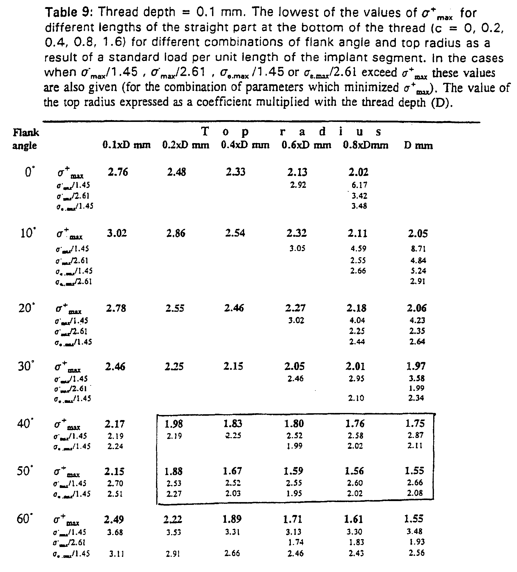

- The radius R has been constant and has been real in the above examples.
- In a preferred embodiment, illustrated in Fig 7, the top radius R at the apex is imaginary and defines a the transition point P1 between the straight flank and the curved apex, a first tangent through P1 being directed along said flank, as well as a crest point P2 on the apex in which a second tangent to the curved part is parallel to the longitudinal direction of the implant. In this embodiment the curved apex has the shape of curved part originating in said points P1 and P2 and has tangents in said points coinciding with said first and second tangents, and has a radius of curvature R1. The radius R1 may for instance increase from a value Rmin to a value Rmax or may increase from a value Rmin to a value Rmax, then decreasing to a value Rmin.
- Rmin should preferably be greater than 0.01 mm and the relationship Rmax/Rmin preferably should be greater than 3.
- One special case of this embodiment is of course that said radius of curvature R1 is constant and equal to said imaginary radius R, the apex thus having a part circular shape with the radius R.
- The following calculations illustrate the effect of the variable radius of curvature.
- Uniform top radius = 0.04 mm
- Flank angle: 40°
- Thread depth: 0.1mm
- Bottom radius: 0.01mm
- Maximum tensile stress: 1.784Mpa
-
- Variable radius of curvature of the thread top-small continuous variations:
- Flank angle: 40°
- Thread depth: 0,1 mm
- Top radius: Rmin=0,025mm, Rmax=0.055mm
- Bottom radius: 0.01 mm
- Maximum tensile stress: 1.750Mpa
-
- Variable radius of curvature of the thread top - bigger continuous variations:
- Flank angle: 40°
- Thread depth: 0,1 mm
- Top radius: Rmin =0.0010mm, Rmax =0.069mm
- Bottom radius: 0.01mm
- Maximum tensile stress: 1.721Mpa
-
- As can be seen in the above, there is some improvement with a variable radius of curvature.
- The invention of course can be varied in many ways within the scope of the appended claims. It should for instance be noted that the two flank angles of the thread or roughness not necessarily have to be identical even if this is a preferred embodiment. In some applications the angles may be different although both are within the ranges specified, in another applications it may be sufficient that the flank being the most heavily loaded has a flank angle within the ranges specified. The same is valid for the top radius which in similarity may have different values on the respective sides of the thread, both values or only one value being within the ranges specified.
Claims (19)
- Thread or oriented macroroughness for bone implants, particularly threaded dental implants, a section of said thread or roughness, i. e. the profile, having a height D and comprising two flanks and a curved apex which connects the two flanks, each flank forming an angle v with a plane which is perpendicular to the cross-section of said thread or roughness and perpendicular to the surface of the implant body, and, for each flank,characterised in that, for each flank, the angle v is in the interval 10° ≤v ≤ 55° , and, for any flank where 10° ≤v < 35°, R is greater than 0.4 x D whereas, for any flank where 35° ≤v ≤55°, R is greater than 0.2 x D.a transition point P1 being defined between the flank and the curved apex, a first tangent to the curved apex through P1 being directed along said flank,a crest point P2 being defined on the curved apex in which a second tangent to the curved apex is parallel to the longitudinal direction of the implant, andan imaginary top radius R at the apex defining a curved part originating in said points P1 and P2 and having tangents in said points coinciding with said first and second tangents,
- Thread or oriented macroroughness according to claim 1, wherein said thread or oriented macroroughness has a bottom length S, and for 0.15 ≤D ≤0.25 mm, 10° ≤v ≤35°, and 0.5 D ≤S ≤2D, R is greater than 0.5 x D but smaller than 0.7 x D.
- Thread or oriented macroroughness according to claim 1, wherein, for 0.05 mm ≤D ≤0.5 mm and 35° ≤v ≤55°, the top radius R is larger than 0.2 x D but smaller than D, and wherein, for 0.25mm ≤D ≤0.5 mm and 35° ≤v ≤55°, R is greater than 0.4x D but smaller than D.
- Thread or oriented macroroughness according to claim 3, wherein, for 0.25 mm ≤D ≤0.5 mm and 10° ≤v ≤35°, R is greater than 0.6 x D but smaller than D.
- Thread or oriented macroroughness according to claim 3, wherein 0.05 ≤D ≤0.25 mm for 35° ≤v ≤55°.
- Thread or oriented macroroughness according to claim 5, wherein 0.05 ≤D ≤0.15 mm for 35° ≤v ≤55°.
- Thread or oriented macroroughness according to claim 6, wherein 0.05 ≤D ≤0.1 mm for 35° ≤v ≤55°.
- Thread or oriented macroroughness according to claim 1, wherein a bottom radius r is formed at the bottom of a groove between two adjacent threads or roughnesses, and 0.03 ≤R ≤0.05 mm, 37° ≤v ≤43°, 0.01 ≤r ≤0.025 mm and 0.08 ≤D ≤0.15 mm.
- Thread or oriented macroroughness according to any one of the preceding claims, wherein the distance between two adjacent threads or roughnesses, crest to crest, is smaller than 3 D, preferably smaller than 2 D.
- Thread or oriented macroroughness according to any one of the preceding claims, wherein said curved apex has a radius of curvature R1, said radius of curvature R1 is constant and equal to said imaginary radius R.
- Thread or oriented macroroughness according to any one of the claims 1-9, wherein said curved apex has a radius of curvature R1, for each flank connecting said transition point P1 and crest point P2, said radius of curvature R1 varies between a minimum value Rmin and a maximum value Rmax.
- Thread or oriented macroroughness according to claim 11, characterised in that the relationship Rmax / Rmin is greater than 3.
- Thread or oriented macroroughness according to claim 11 or 12, characterised in that Rmin is greater than 0.01 mm.
- Thread or oriented macroroughness according to any one of the preceding claims characterised in that said profile is symmetric.
- Thread or oriented macroroughness according to any one of claims 1 to 13, characterised in that said imaginary top radius R or radius of curvature R1 is located on one first thread flank, the second thread flank being provided with another radius at the apex of the thread which is different from said first radius and which has one tangent coinciding with said second flank and one tangent through P2 which is parallel with the longitudinal axis of the implant.
- Thread or oriented macroroughness according to any one of claims 1 to 13, characterised in that said imaginary top radius R or radius of curvature R1 is located on one first thread flank, the second thread flank being provided with another radius at the apex of the thread which is the same as said first radius and which has one tangent coinciding with said second flank and one tangent through P2 which is parallel with the longitudinal axis of the implant.
- Thread or oriented macroroughness according to any one of the preceding claims, characterised in that said threads or macroroughness is combined with a superimposed microroughness having a pore size of 2 µ to 20 µ, preferably 2 µ to 10 µ.
- Implant characterised in that said implant at least partly is provided with threads or oriented macroroughness according to any one of the preceding claims.
- Implant according to claim 18, characterised in that said implant is provided with at least one additional, different thread.
Applications Claiming Priority (3)
| Application Number | Priority Date | Filing Date | Title |
|---|---|---|---|
| SE9600517A SE9600517D0 (en) | 1996-02-13 | 1996-02-13 | Screw thread implant |
| SE9600517 | 1996-02-13 | ||
| PCT/SE1997/000212 WO1997029713A1 (en) | 1996-02-13 | 1997-02-12 | Screw thread implant |
Publications (2)
| Publication Number | Publication Date |
|---|---|
| EP0959801A1 EP0959801A1 (en) | 1999-12-01 |
| EP0959801B1 true EP0959801B1 (en) | 2003-12-03 |
Family
ID=20401367
Family Applications (1)
| Application Number | Title | Priority Date | Filing Date |
|---|---|---|---|
| EP97903696A Expired - Lifetime EP0959801B1 (en) | 1996-02-13 | 1997-02-12 | Screw thread implant |
Country Status (21)
| Country | Link |
|---|---|
| US (1) | US6036491A (en) |
| EP (1) | EP0959801B1 (en) |
| JP (1) | JP4374083B2 (en) |
| KR (1) | KR100484687B1 (en) |
| AR (1) | AR005810A1 (en) |
| AT (1) | ATE255376T1 (en) |
| AU (1) | AU702009B2 (en) |
| BR (1) | BR9707507A (en) |
| CA (1) | CA2243086C (en) |
| DE (1) | DE69726608T2 (en) |
| DK (1) | DK0959801T3 (en) |
| ES (1) | ES2212073T3 (en) |
| IL (1) | IL125533A0 (en) |
| IS (1) | IS1799B (en) |
| NO (1) | NO324684B1 (en) |
| PL (1) | PL185735B1 (en) |
| PT (1) | PT959801E (en) |
| RU (1) | RU2181990C2 (en) |
| SE (1) | SE9600517D0 (en) |
| WO (1) | WO1997029713A1 (en) |
| ZA (1) | ZA971181B (en) |
Families Citing this family (33)
| Publication number | Priority date | Publication date | Assignee | Title |
|---|---|---|---|---|
| SE9802571D0 (en) | 1998-07-17 | 1998-07-17 | Astra Ab | Implant |
| SE9802572D0 (en) * | 1998-07-17 | 1998-07-17 | Astra Ab | Dental implant |
| EP1104753A1 (en) | 1999-12-03 | 2001-06-06 | Dsm N.V. | Process for recovering monomeric units of a nylon from whole carpet |
| TW491714B (en) * | 1999-12-08 | 2002-06-21 | Wen-Jing Shiue | Orthopedic implant having a porous surface and method of making same |
| US7137817B2 (en) * | 2000-12-22 | 2006-11-21 | Quantum Bioengineering, Ltd. | Implant fixation device |
| US6726084B2 (en) * | 2001-06-15 | 2004-04-27 | Lockheed Martin Corporation | Friction stir heating/welding with pin tool having rough distal region |
| SE0102749D0 (en) † | 2001-08-15 | 2001-08-15 | Astra Tech Ab | Implant, arrangement including an implant, and method of inserting said implant into bone tissue |
| US6953463B2 (en) * | 2001-10-12 | 2005-10-11 | Hs West Investments, Llc | Interference screws having increased proximal diameter |
| SE523395C2 (en) * | 2001-12-21 | 2004-04-13 | Nobel Biocare Ab | Implants and methods and systems for providing such implants |
| SE520756C2 (en) | 2001-12-21 | 2003-08-19 | Nobel Biocare Ab | Method of providing surface structure on implants as well as such implants |
| JP3820390B2 (en) * | 2002-08-26 | 2006-09-13 | 株式会社アイキャット | Artificial root placement position calculation method, artificial root placement position calculation device, computer program, and recording medium |
| IL158789A (en) | 2002-11-13 | 2009-11-18 | Biomet 3I Llc | Dental implant system |
| RU2226080C1 (en) * | 2002-12-18 | 2004-03-27 | Абдуллаев Фикрет Мавлудинович | Method for stimulating osteogenesis processes in carrying out intraosseous implantation |
| US8651863B2 (en) * | 2003-04-01 | 2014-02-18 | Robert Schroering | Band of connective tissue grooves for use with a dental implant or a separate abutment for a dental implant |
| US20090233256A1 (en) * | 2008-03-14 | 2009-09-17 | Robert Schroering | Band of Connective Tissue Grooves for Use with a Dental Implant or a Separate Abutment for a Dental Implant |
| US20040230195A1 (en) * | 2003-05-14 | 2004-11-18 | Inion Ltd. | Soft-tissue screw |
| KR101069542B1 (en) * | 2005-09-02 | 2011-10-05 | 찌테리온 게엠베하 | Immediate-load dental implants |
| EP1792580A1 (en) * | 2005-09-27 | 2007-06-06 | Ziterion GmbH | Two-part dental implants made of biocompatible ceramics |
| EP1870054A3 (en) * | 2006-06-12 | 2008-05-14 | Vilardell Purti, S.A. | Dental implant |
| EA010624B1 (en) * | 2006-10-23 | 2008-10-30 | Производственное Частное Унитарное Предприятие "Верлайн" | Polycomponent dental implant |
| DE102006054533A1 (en) * | 2006-11-15 | 2008-05-21 | Resoimplant Gmbh | Fixation element for bone fragment |
| US20080234763A1 (en) * | 2007-03-16 | 2008-09-25 | Patterson Chad J | Surgical compression bone screw |
| US8574273B2 (en) | 2009-09-09 | 2013-11-05 | Innovision, Inc. | Bone screws and methods of use thereof |
| US9393006B2 (en) * | 2009-10-28 | 2016-07-19 | Smith & Nephew, Inc. | Threaded suture anchor |
| IL201902A (en) * | 2009-11-03 | 2012-12-31 | Ben-Zion Karmon | Dental implant |
| EP2510898A1 (en) * | 2011-04-14 | 2012-10-17 | Astra Tech AB | Fixture |
| US9925024B2 (en) | 2011-06-28 | 2018-03-27 | Biomet 3I, Llc | Dental implant and abutment tools |
| EP2967694B1 (en) | 2013-03-15 | 2022-04-20 | INNOVISION, Inc. | Bone screws |
| DE102013107630A1 (en) * | 2013-07-17 | 2015-01-22 | Hochschule Koblenz | Dental implant with coronal groove structure |
| US10413387B2 (en) * | 2015-01-20 | 2019-09-17 | John Andler | Threaded dental implant |
| US11648037B2 (en) | 2017-05-03 | 2023-05-16 | Advance Research System, Llc | Extension-ready spinal support system with vascular-safe pedicle screw |
| WO2018204676A1 (en) | 2017-05-03 | 2018-11-08 | Advance Research System, Llc | Extension ready spinal support systems |
| TWI763162B (en) * | 2020-12-04 | 2022-05-01 | 鐿鈦科技股份有限公司 | Suture anchor, system and implantation method therefor |
Family Cites Families (9)
| Publication number | Priority date | Publication date | Assignee | Title |
|---|---|---|---|---|
| DE2621384C3 (en) * | 1976-05-14 | 1978-12-07 | Pfaudler-Werke Ag, 6830 Schwetzingen | Medical fastener and method of making it |
| EP0209685A3 (en) * | 1985-07-12 | 1988-11-09 | Fischerwerke Arthur Fischer GmbH & Co. KG | Fixation element for osteosynthesis |
| EP0230678A1 (en) * | 1986-01-29 | 1987-08-05 | Massimiliano Barcali | Endosteal screw-implant |
| JP2580677B2 (en) * | 1988-02-23 | 1997-02-12 | 三菱マテリアル株式会社 | Artificial root |
| SE9102451L (en) * | 1991-08-27 | 1992-11-16 | Nobelpharma Ab | SCREW SIZE TITAN MOUNTING FOR PERMANENT ANCHORING IN BONE TISSUE. |
| IT1253481B (en) * | 1991-10-08 | 1995-08-08 | SCREW ENDOSSEO DENTAL IMPLANT. | |
| SE9202911D0 (en) * | 1992-10-05 | 1992-10-05 | Astra Ab | FIXTURE PROVIDED WITH MICRO-THREADS |
| SE9203184D0 (en) * | 1992-10-28 | 1992-10-28 | Astra Ab | DENTAL IMPLANT |
| US5571139A (en) * | 1995-05-19 | 1996-11-05 | Jenkins, Jr.; Joseph R. | Bidirectional suture anchor |
-
1996
- 1996-02-13 SE SE9600517A patent/SE9600517D0/en unknown
-
1997
- 1997-02-12 DE DE69726608T patent/DE69726608T2/en not_active Expired - Lifetime
- 1997-02-12 BR BR9707507A patent/BR9707507A/en not_active IP Right Cessation
- 1997-02-12 ES ES97903696T patent/ES2212073T3/en not_active Expired - Lifetime
- 1997-02-12 KR KR10-1998-0706233A patent/KR100484687B1/en not_active Expired - Lifetime
- 1997-02-12 WO PCT/SE1997/000212 patent/WO1997029713A1/en not_active Ceased
- 1997-02-12 DK DK97903696T patent/DK0959801T3/en active
- 1997-02-12 PL PL97328428A patent/PL185735B1/en not_active IP Right Cessation
- 1997-02-12 PT PT97903696T patent/PT959801E/en unknown
- 1997-02-12 IL IL12553397A patent/IL125533A0/en not_active IP Right Cessation
- 1997-02-12 EP EP97903696A patent/EP0959801B1/en not_active Expired - Lifetime
- 1997-02-12 AU AU18170/97A patent/AU702009B2/en not_active Ceased
- 1997-02-12 AT AT97903696T patent/ATE255376T1/en active
- 1997-02-12 US US08/809,261 patent/US6036491A/en not_active Expired - Lifetime
- 1997-02-12 RU RU98114794/14A patent/RU2181990C2/en active
- 1997-02-12 JP JP52926197A patent/JP4374083B2/en not_active Expired - Lifetime
- 1997-02-12 ZA ZA9701181A patent/ZA971181B/en unknown
- 1997-02-12 CA CA002243086A patent/CA2243086C/en not_active Expired - Fee Related
- 1997-02-13 AR ARP970100575A patent/AR005810A1/en unknown
-
1998
- 1998-07-31 IS IS4815A patent/IS1799B/en unknown
- 1998-08-12 NO NO19983692A patent/NO324684B1/en not_active IP Right Cessation
Also Published As
| Publication number | Publication date |
|---|---|
| NO324684B1 (en) | 2007-12-03 |
| ATE255376T1 (en) | 2003-12-15 |
| AU1817097A (en) | 1997-09-02 |
| DE69726608T2 (en) | 2004-10-14 |
| ZA971181B (en) | 1997-08-13 |
| ES2212073T3 (en) | 2004-07-16 |
| WO1997029713A1 (en) | 1997-08-21 |
| KR19990082500A (en) | 1999-11-25 |
| PL185735B1 (en) | 2003-07-31 |
| NO983692D0 (en) | 1998-08-12 |
| DE69726608D1 (en) | 2004-01-15 |
| SE9600517D0 (en) | 1996-02-13 |
| KR100484687B1 (en) | 2005-11-25 |
| DK0959801T3 (en) | 2004-01-26 |
| IS1799B (en) | 2002-01-10 |
| PL328428A1 (en) | 1999-02-01 |
| BR9707507A (en) | 1999-07-27 |
| NO983692L (en) | 1998-09-29 |
| IS4815A (en) | 1998-07-31 |
| AR005810A1 (en) | 1999-07-14 |
| CA2243086C (en) | 2007-06-12 |
| EP0959801A1 (en) | 1999-12-01 |
| AU702009B2 (en) | 1999-02-11 |
| US6036491A (en) | 2000-03-14 |
| RU2181990C2 (en) | 2002-05-10 |
| JP4374083B2 (en) | 2009-12-02 |
| JP2000504607A (en) | 2000-04-18 |
| IL125533A0 (en) | 1999-03-12 |
| PT959801E (en) | 2004-04-30 |
| CA2243086A1 (en) | 1997-08-21 |
Similar Documents
| Publication | Publication Date | Title |
|---|---|---|
| US6036491A (en) | Screw thread implant | |
| US6102956A (en) | Modular endoprosthesis | |
| US11006990B2 (en) | Method of making a self-cleaning self-cutting implant | |
| CN1154441C (en) | Fixation system for bone | |
| US6508820B2 (en) | Intramedullary interlock screw | |
| KR101066312B1 (en) | Multi-screwed bone screws and methods | |
| CN103356277B (en) | Hone lamella | |
| US3781917A (en) | Hip joint prosthesis | |
| US20230398657A1 (en) | Implant with high primary stability and accelerated secondary stability | |
| JP2002542875A (en) | Bone plate that can be blocked | |
| CN102188282A (en) | Bone fixation system with curved profile threads | |
| KR20010071941A (en) | Implant | |
| CH710695A2 (en) | Device for variable fixation of bone fragments. | |
| KR20160033143A (en) | Tooth implant with coronal groove structure | |
| US12383380B2 (en) | Dental implant with improved threading | |
| US4919677A (en) | Prosthetic acetabulum | |
| US20070009854A1 (en) | Dental or medical implants and method therefor | |
| US20200405353A1 (en) | Assemblable artificial bone plate and artificial bone plate unit | |
| KR102082120B1 (en) | Fixture for implant | |
| US20230200951A1 (en) | Dental implant made of a metal or a metal alloy | |
| CN224179811U (en) | A dental implant | |
| JP2001523133A (en) | Implant device | |
| CN117159191A (en) | Dental implant | |
| JP2013094628A (en) | External fixation pin | |
| Hansson | Toward an optimized dental implant design |
Legal Events
| Date | Code | Title | Description |
|---|---|---|---|
| PUAI | Public reference made under article 153(3) epc to a published international application that has entered the european phase |
Free format text: ORIGINAL CODE: 0009012 |
|
| 17P | Request for examination filed |
Effective date: 19980914 |
|
| AK | Designated contracting states |
Kind code of ref document: A1 Designated state(s): AT BE CH DE DK ES FI FR GB GR IE IT LI NL PT SE |
|
| RAP1 | Party data changed (applicant data changed or rights of an application transferred) |
Owner name: ASTRAZENECA AB |
|
| 17Q | First examination report despatched |
Effective date: 20020529 |
|
| RAP1 | Party data changed (applicant data changed or rights of an application transferred) |
Owner name: ASTRA TECH AB |
|
| GRAH | Despatch of communication of intention to grant a patent |
Free format text: ORIGINAL CODE: EPIDOS IGRA |
|
| GRAS | Grant fee paid |
Free format text: ORIGINAL CODE: EPIDOSNIGR3 |
|
| GRAA | (expected) grant |
Free format text: ORIGINAL CODE: 0009210 |
|
| AK | Designated contracting states |
Kind code of ref document: B1 Designated state(s): AT BE CH DE DK ES FI FR GB GR IE IT LI NL PT SE |
|
| REG | Reference to a national code |
Ref country code: GB Ref legal event code: FG4D |
|
| REG | Reference to a national code |
Ref country code: CH Ref legal event code: EP |
|
| REG | Reference to a national code |
Ref country code: IE Ref legal event code: FG4D |
|
| REF | Corresponds to: |
Ref document number: 69726608 Country of ref document: DE Date of ref document: 20040115 Kind code of ref document: P |
|
| REG | Reference to a national code |
Ref country code: DK Ref legal event code: T3 |
|
| REG | Reference to a national code |
Ref country code: SE Ref legal event code: TRGR |
|
| REG | Reference to a national code |
Ref country code: GR Ref legal event code: EP Ref document number: 20040400743 Country of ref document: GR |
|
| REG | Reference to a national code |
Ref country code: PT Ref legal event code: SC4A Free format text: AVAILABILITY OF NATIONAL TRANSLATION Effective date: 20040303 Ref country code: CH Ref legal event code: NV Representative=s name: BUGNION S.A. |
|
| REG | Reference to a national code |
Ref country code: ES Ref legal event code: FG2A Ref document number: 2212073 Country of ref document: ES Kind code of ref document: T3 |
|
| ET | Fr: translation filed | ||
| PLBE | No opposition filed within time limit |
Free format text: ORIGINAL CODE: 0009261 |
|
| STAA | Information on the status of an ep patent application or granted ep patent |
Free format text: STATUS: NO OPPOSITION FILED WITHIN TIME LIMIT |
|
| 26N | No opposition filed |
Effective date: 20040906 |
|
| REG | Reference to a national code |
Ref country code: FR Ref legal event code: PLFP Year of fee payment: 20 |
|
| PGFP | Annual fee paid to national office [announced via postgrant information from national office to epo] |
Ref country code: CH Payment date: 20160203 Year of fee payment: 20 Ref country code: IT Payment date: 20160205 Year of fee payment: 20 Ref country code: IE Payment date: 20160201 Year of fee payment: 20 Ref country code: ES Payment date: 20160225 Year of fee payment: 20 Ref country code: DE Payment date: 20160202 Year of fee payment: 20 Ref country code: DK Payment date: 20160203 Year of fee payment: 20 |
|
| PGFP | Annual fee paid to national office [announced via postgrant information from national office to epo] |
Ref country code: SE Payment date: 20160215 Year of fee payment: 20 Ref country code: BE Payment date: 20160201 Year of fee payment: 20 Ref country code: PT Payment date: 20160120 Year of fee payment: 20 Ref country code: FI Payment date: 20160202 Year of fee payment: 20 Ref country code: GR Payment date: 20160208 Year of fee payment: 20 Ref country code: FR Payment date: 20160208 Year of fee payment: 20 Ref country code: AT Payment date: 20160202 Year of fee payment: 20 Ref country code: NL Payment date: 20160212 Year of fee payment: 20 Ref country code: GB Payment date: 20160204 Year of fee payment: 20 |
|
| REG | Reference to a national code |
Ref country code: DE Ref legal event code: R071 Ref document number: 69726608 Country of ref document: DE |
|
| REG | Reference to a national code |
Ref country code: DK Ref legal event code: EUP Effective date: 20170212 |
|
| REG | Reference to a national code |
Ref country code: CH Ref legal event code: PL Ref country code: NL Ref legal event code: MK Effective date: 20170211 |
|
| REG | Reference to a national code |
Ref country code: GB Ref legal event code: PE20 Expiry date: 20170211 |
|
| REG | Reference to a national code |
Ref country code: IE Ref legal event code: MK9A |
|
| REG | Reference to a national code |
Ref country code: SE Ref legal event code: EUG |
|
| REG | Reference to a national code |
Ref country code: AT Ref legal event code: MK07 Ref document number: 255376 Country of ref document: AT Kind code of ref document: T Effective date: 20170212 |
|
| REG | Reference to a national code |
Ref country code: GR Ref legal event code: MA Ref document number: 20040400743 Country of ref document: GR Effective date: 20170213 |
|
| REG | Reference to a national code |
Ref country code: ES Ref legal event code: FD2A Effective date: 20170526 |
|
| PG25 | Lapsed in a contracting state [announced via postgrant information from national office to epo] |
Ref country code: PT Free format text: LAPSE BECAUSE OF EXPIRATION OF PROTECTION Effective date: 20170221 Ref country code: IE Free format text: LAPSE BECAUSE OF EXPIRATION OF PROTECTION Effective date: 20170212 Ref country code: GB Free format text: LAPSE BECAUSE OF EXPIRATION OF PROTECTION Effective date: 20170211 |
|
| PG25 | Lapsed in a contracting state [announced via postgrant information from national office to epo] |
Ref country code: ES Free format text: LAPSE BECAUSE OF EXPIRATION OF PROTECTION Effective date: 20170213 |