EP0959375A2 - Atténuateur optique - Google Patents
Atténuateur optique Download PDFInfo
- Publication number
- EP0959375A2 EP0959375A2 EP99109802A EP99109802A EP0959375A2 EP 0959375 A2 EP0959375 A2 EP 0959375A2 EP 99109802 A EP99109802 A EP 99109802A EP 99109802 A EP99109802 A EP 99109802A EP 0959375 A2 EP0959375 A2 EP 0959375A2
- Authority
- EP
- European Patent Office
- Prior art keywords
- lens
- light
- input
- optical
- waveguide
- Prior art date
- Legal status (The legal status is an assumption and is not a legal conclusion. Google has not performed a legal analysis and makes no representation as to the accuracy of the status listed.)
- Withdrawn
Links
Images


Classifications
-
- G—PHYSICS
- G02—OPTICS
- G02B—OPTICAL ELEMENTS, SYSTEMS OR APPARATUS
- G02B6/00—Light guides; Structural details of arrangements comprising light guides and other optical elements, e.g. couplings
- G02B6/24—Coupling light guides
- G02B6/26—Optical coupling means
- G02B6/28—Optical coupling means having data bus means, i.e. plural waveguides interconnected and providing an inherently bidirectional system by mixing and splitting signals
- G02B6/2804—Optical coupling means having data bus means, i.e. plural waveguides interconnected and providing an inherently bidirectional system by mixing and splitting signals forming multipart couplers without wavelength selective elements, e.g. "T" couplers, star couplers
- G02B6/2848—Optical coupling means having data bus means, i.e. plural waveguides interconnected and providing an inherently bidirectional system by mixing and splitting signals forming multipart couplers without wavelength selective elements, e.g. "T" couplers, star couplers having refractive means, e.g. imaging elements between light guides as splitting, branching and/or combining devices, e.g. lenses, holograms
-
- G—PHYSICS
- G02—OPTICS
- G02B—OPTICAL ELEMENTS, SYSTEMS OR APPARATUS
- G02B27/00—Optical systems or apparatus not provided for by any of the groups G02B1/00 - G02B26/00, G02B30/00
- G02B27/28—Optical systems or apparatus not provided for by any of the groups G02B1/00 - G02B26/00, G02B30/00 for polarising
- G02B27/283—Optical systems or apparatus not provided for by any of the groups G02B1/00 - G02B26/00, G02B30/00 for polarising used for beam splitting or combining
-
- G—PHYSICS
- G02—OPTICS
- G02B—OPTICAL ELEMENTS, SYSTEMS OR APPARATUS
- G02B6/00—Light guides; Structural details of arrangements comprising light guides and other optical elements, e.g. couplings
- G02B6/24—Coupling light guides
- G02B6/26—Optical coupling means
- G02B6/264—Optical coupling means with optical elements between opposed fibre ends which perform a function other than beam splitting
- G02B6/266—Optical coupling means with optical elements between opposed fibre ends which perform a function other than beam splitting the optical element being an attenuator
-
- G—PHYSICS
- G02—OPTICS
- G02B—OPTICAL ELEMENTS, SYSTEMS OR APPARATUS
- G02B6/00—Light guides; Structural details of arrangements comprising light guides and other optical elements, e.g. couplings
- G02B6/24—Coupling light guides
- G02B6/26—Optical coupling means
- G02B6/27—Optical coupling means with polarisation selective and adjusting means
- G02B6/2706—Optical coupling means with polarisation selective and adjusting means as bulk elements, i.e. free space arrangements external to a light guide, e.g. polarising beam splitters
- G02B6/2713—Optical coupling means with polarisation selective and adjusting means as bulk elements, i.e. free space arrangements external to a light guide, e.g. polarising beam splitters cascade of polarisation selective or adjusting operations
- G02B6/272—Optical coupling means with polarisation selective and adjusting means as bulk elements, i.e. free space arrangements external to a light guide, e.g. polarising beam splitters cascade of polarisation selective or adjusting operations comprising polarisation means for beam splitting and combining
-
- G—PHYSICS
- G02—OPTICS
- G02B—OPTICAL ELEMENTS, SYSTEMS OR APPARATUS
- G02B6/00—Light guides; Structural details of arrangements comprising light guides and other optical elements, e.g. couplings
- G02B6/24—Coupling light guides
- G02B6/26—Optical coupling means
- G02B6/27—Optical coupling means with polarisation selective and adjusting means
- G02B6/2746—Optical coupling means with polarisation selective and adjusting means comprising non-reciprocal devices, e.g. isolators, FRM, circulators, quasi-isolators
-
- G—PHYSICS
- G02—OPTICS
- G02B—OPTICAL ELEMENTS, SYSTEMS OR APPARATUS
- G02B6/00—Light guides; Structural details of arrangements comprising light guides and other optical elements, e.g. couplings
- G02B6/24—Coupling light guides
- G02B6/26—Optical coupling means
- G02B6/27—Optical coupling means with polarisation selective and adjusting means
- G02B6/2753—Optical coupling means with polarisation selective and adjusting means characterised by their function or use, i.e. of the complete device
- G02B6/2773—Polarisation splitting or combining
-
- G—PHYSICS
- G02—OPTICS
- G02B—OPTICAL ELEMENTS, SYSTEMS OR APPARATUS
- G02B6/00—Light guides; Structural details of arrangements comprising light guides and other optical elements, e.g. couplings
- G02B6/24—Coupling light guides
- G02B6/26—Optical coupling means
- G02B6/28—Optical coupling means having data bus means, i.e. plural waveguides interconnected and providing an inherently bidirectional system by mixing and splitting signals
- G02B6/293—Optical coupling means having data bus means, i.e. plural waveguides interconnected and providing an inherently bidirectional system by mixing and splitting signals with wavelength selective means
- G02B6/29346—Optical coupling means having data bus means, i.e. plural waveguides interconnected and providing an inherently bidirectional system by mixing and splitting signals with wavelength selective means operating by wave or beam interference
- G02B6/29361—Interference filters, e.g. multilayer coatings, thin film filters, dichroic splitters or mirrors based on multilayers, WDM filters
- G02B6/2937—In line lens-filtering-lens devices, i.e. elements arranged along a line and mountable in a cylindrical package for compactness, e.g. 3- port device with GRIN lenses sandwiching a single filter operating at normal incidence in a tubular package
-
- G—PHYSICS
- G02—OPTICS
- G02B—OPTICAL ELEMENTS, SYSTEMS OR APPARATUS
- G02B6/00—Light guides; Structural details of arrangements comprising light guides and other optical elements, e.g. couplings
- G02B6/24—Coupling light guides
- G02B6/26—Optical coupling means
- G02B6/28—Optical coupling means having data bus means, i.e. plural waveguides interconnected and providing an inherently bidirectional system by mixing and splitting signals
- G02B6/293—Optical coupling means having data bus means, i.e. plural waveguides interconnected and providing an inherently bidirectional system by mixing and splitting signals with wavelength selective means
- G02B6/29379—Optical coupling means having data bus means, i.e. plural waveguides interconnected and providing an inherently bidirectional system by mixing and splitting signals with wavelength selective means characterised by the function or use of the complete device
- G02B6/29392—Controlling dispersion
- G02B6/29394—Compensating wavelength dispersion
-
- G—PHYSICS
- G02—OPTICS
- G02B—OPTICAL ELEMENTS, SYSTEMS OR APPARATUS
- G02B6/00—Light guides; Structural details of arrangements comprising light guides and other optical elements, e.g. couplings
- G02B6/24—Coupling light guides
- G02B6/26—Optical coupling means
- G02B6/32—Optical coupling means having lens focusing means positioned between opposed fibre ends
Definitions
- This invention relates to an optical attenuator for controllably attenuating optical signals.
- Attenuators are known in the art. Some of these, use polarizing beam-splitters also known in the art, each having disadvantages. Furthermore, attenuators utilizing beam splitting to split an incoming beam into two polarized beams, have required one beam splitter to split an incoming beam into two orthogonally polarized beams, and one substantially identical beam splitter to combine the polarized beams into a single beam of light. Providing a matched pair of crystals can be challenging and is costly.
- the Glan-Thompson polarizer which is a block of birefringent material cut into prisms and then cemented together acts by reflecting one polarization component at the cement interface and by transmitting the other.
- the device requires a considerable amount of birefringent material, generally calcite, which is scarce and expensive, and is unable to work with high powered lasers and ultraviolet light, since the light destroys or clouds cement.
- this beam-splitter which makes use of the reflected polarization component, suffers from the added disadvantage that polarized beams exit the device at inconvenient angles, for example 45 degrees, when it is often useful that beams are parallel, orthogonal or otherwise oriented.
- the Glan-Taylor polarizer which is similar to the Glan-Thompson polarizer but uses an air space instead of cement to separate polarization components can work with many light sources but suffers from reflection loss and ghosting caused by the air gap.
- the Wollaston, Rochon and Senarmont beam-splitters which separates polarization components by transmitting the components through an interface, permit optical contacting for use with most light sources, but produce beams which also exit at inconvenient angles, with one or both polarization components suffering from chromatism and distortion.
- the double refracting element which produces parallel polarized beams of light, achieves small beam separation and limited field. Also, since the beams may pass through a considerable amount of material before achieving useful separation, wavefront distortion can occur in the extraordinary beam due to imperfections in the crystal's structure. (See for example, "Birefringence of Quartz and Calcite,” Journal of the Optical Society of America, volume 49, No. 7, Jul. 1961, pages 710-712.) Beam separation can be further limited by the small size and high cost of suitable crystals. Notwithstanding, it is an object of the invention to overcome some of these limitations while using a beam displacing crystal.
- the present invention obviates most or all of these disadvantages and results in a small relatively inexpensive optical attenuator.
- an optical attenuator comprising:
- optical attenuator comprising:
- an optical attenuator comprising:
- this invention provides a structure that requires a substantially smaller (approximately 1/50 th the size of) birefringent crystal than is required in most commercially available devices of a similar design utilizing birefringent beam shifting crystals.
- Fig. 1 depicts a well known polarization beam splitter/coupler design, wherein a birefringent crystal 10 such as a calcite crystal is disposed adjacent three quarter pitch focusing/collimating graded index lenses, 12a and 12b at a first end face and 12c at an opposite end face of the crystal disposed to receive light from the other two lenses. It is noted in Fig. 1, that the beam widths 14a, 14b at an end face of one of the lenses denoted by a heavy black line at the lens-crystal interface, defines a length that is less than the minimum size of the crystal end face, which must be sized to accommodate the beams including some additional adjustment space denoted by the length d 2 .
- a birefringent crystal 10 such as a calcite crystal is disposed adjacent three quarter pitch focusing/collimating graded index lenses, 12a and 12b at a first end face and 12c at an opposite end face of the crystal disposed to receive light from the other two lenses.
- a polarizing beam splitter/combiner having two waveguides in the form of optical fibres 16a and 16b directly coupled, using fibre tubes, not shown, to an end face of a small birefringent crystal 30.
- the size of the crystal 30 required in the embodiment of Fig. 3a is approximately 1/50 th the size of the crystal 10 required in the conventional beam splitter shown in Fig. 1.
- the cost saving of manufacturing the device of Fig. 3a is significantly less than the device of shown in Fig. 1.
- only one lens is required in the first embodiment of the invention, compared with three lenses required in the prior art device shown in Fig. 1.
- an output optical waveguide in the form of an optical fibre is disposed a distance from the end face of the crystal 30.
- a lens 32 is disposed between the optical fibre 16c and the crystal 30 for coupling light between the optical fibres 16a and 16c and between the optical fibres 16b and 16c.
- the size of the crystal 30 can be made very small, resulting in considerable cost savings. Furthermore it becomes practicable to propagate beams from the fibres 16a and 16b through the crystal 30 as uncollimated beams, and to couple these beams with the optical fibre 16c via a lens 32, only if the crystal is very short in length; it is apparent that the beam diameter propagating through the crystal increases as the length of the crystal increases.
- the device shown in Fig. 3a works in the following manner.
- a beam splitter light of unknown polarization is launched into optical fibre 16c, which functions as an input port.
- optical fibre 16c which functions as an input port.
- the o-ray polarized beam is directed by the crystal port 16a and the e-ray polarized light is directed to port 16b.
- combining is performed in a same manner in an opposite direction. Since no lens is present between the fibres 16a, 16b and the crystal 30, light traversing the short length of the crystal is non-collimated.
- lenses of various types are used to collimate a diverging light beam exiting an optical waveguide and to focus light that is launched into an optical waveguide so as to more efficiently couple the light.
- GRIN graded index
- GRIN lenses are relatively inexpensive, compact, and furthermore have parallel flat end faces.
- the flat end face of the GRIN lens allows a single lens to be used as a means of collimating or focusing the light, and as well, as a means of tapping light reflected from the end face of the lens.
- a substantially quarter pitch GRIN lens is shown, with traces of three beams launched from three locations, 41c, 41b, and 41a adjacent an end face of the lens 42.
- the beam launched from location 41c is shown to be expanding and entering the lens with a wider diameter than the other two beams launched from locations 41b and 41a. This also illustrates that when light is launched into the opposite end of the lens as a collimated beam, the focusing location(s) of the beam is dependent upon the beam diameter.
- a lens such as a GRIN lens
- the beam entering the lens 32 propagating toward the optical fibre 16c from one of 16a and/or 16b has a diameter that is too wide, some of the light entering the periphery of the lens will not be efficiently coupled into the receiving end of the optical fibre 16c.
- Fig. 3d illustrates an alternative embodiment of the invention wherein the beam propagating from the optical fibre 16a toward 16c has a relatively small diameter, and wherein the diameter of the beam entering the lenses 42 is approximately half of the diameter of the beam entering the lens 42 in the arrangements shown in Fig. 3c or 3a.
- a pair of quarter pitch GRIN lenses 110a and 110b are shown having their collimating ends inwardly facing and their focusing ends outwardly facing.
- Two optical waveguides 111a and 111b are shown coaxial with and coupled to the lenses along at the optical axis of the lenses 110a and 110b shown by a dotted line.
- a beam profile is also shown within the lenses 110a and 110b as if light was launched from one of the waveguides 111a and 111b to a respective lens. It should be noted that the beam profile at the interface between the two lenses extends to a circumference about the lens indicated by points 12a and 12b, being two points on the circumference.
- Fig. 4b illustrates the same pair of GRIN lenses as in Fig. 4a, however the two optical waveguides 111a and 111b are shown to be offset a same optical distance from the common optical axis of the lenses 110a and 110b.
- the beam profile at the interface between the two lenses extends to the same circumference as in Fig. 4a, however the angle of the beam has varied.
- the lenses shown in Fig. 4c are now spaced apart a fixed distance.
- the optical axis of the waveguide 11 is shown to be parallel to the optical axis OA of the lens 110a.
- it in order to efficiently couple light from the output waveguide 111b, it must be non-parallel to the input waveguide 111a and at an angle q with respect to the optical axis of the lens 110b, dependent upon the amount of separation. Essentially as the separation increases between the two lenses, the output beam diverges from the optical axis of lens 110b.
- the lenses 110a and 110b are shown having no gap between them, however, the input and output optical waveguides 111a and 111b are spaced from the end faces of the lenses they are optically coupled therewith. As a result of this gap, the light coupling into the optical fibre 111b is at an angle q and light does not couple efficiently into the waveguide.
- light can efficiently be coupled from an input waveguide to an output waveguide that are both substantially parallel with an optical axis of one of the lenses 110a or 110b by ensuring that the spacing of the input waveguides and the spacing between adjacent lenses is within a predetermined ratio. More particularly, the lenses 110a and 110b shown in Fig. 4f are spaced an optical distance l 3 .
- the input waveguides 111a and 11c are an optical distance l 1 from the end face of the lens 110a.
- the output waveguides 111b and 11d are an optical distance l 2 from their adjacent lens 110b.
- two identical birefringent crystals 50a and 50b are shown wherein each is half the length of the crystal 30. Disposed between the crystals 50a and 50b are two substantially focusing lenses having their focus location a distance from their end faces, midway between the lenses 42. Waveguides 16a and 16b are coupled to an end of one of the crystals 50a and waveguide 16c is coupled to the crystal 50b.
- o-ray oriented light launched into port 16a is directed to port 16c across the device as in the previous embodiments and e-ray oriented light launched into oft 16b is directed to port 16c for combining with the o-ray oriented light.
- the crystal 42 is shorter than the crystal 30, the beam entering the lens 42 adjacent 50a is much smaller and a preferred portion of the lens 50a is used.
- the region about the periphery of the lens 50b is unused and optimum coupling is achieved from the port at 16a to 16c, and 16b to 16c.
- d 1 the distance from the ports to the nearest lens is twice the distance 2d 1 between the two lenses.
- the lenses are illustrated as having end faces that are orthogonal to the lens axis, in practice, the lens may be polished and slanted to reduce the affect of unwanted back reflections.
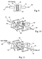
- a prior art optical attenuator/switch having a first GRIN lens 51 associated with an input fibre 57, a second GRIN lens 55 associated with an output fibre, a first wedge-shaped birefringent polarizer 52, a liquid crystal cell 50, and a second wedge-shaped birefringent polarizer 54.
- the ferrules holding the fibres 57 and 58 are not shown here but are shown in Fig. 10 as 51 and 58.
- the liquid crystal cell 50 controllably rotates the light signals from the first GRIN lens 51.
- the optical signal may or may not be transmitted to the output fibre 58.
- Fig. 10 illustrates the orientation of the various optical axes of the polarizers 52 and 54 and the liquid crystal cell 50 of Fig. 9.
- the optical axis of the first polarizer 52 is arranged in an arbitrary direction perpendicular to the line of travel of the collimated light signal from the first GRIN lens 51.
- the optical axis of the second polarizer 54 is arranged so that it is rotated 90 degrees from the optical axis of the firs polarizer 52 and perpendicular to the line of travel of the collimated light beam.
- the optical axis of the liquid crystal is 45 degrees from the optical axis of the first polarizer 52 and the cell 50 has a thickness such that there is is 180 degrees phase retardation of the light signal as it travels through the cell 50.
- Fig. 11 The operation of this prior art switch/attenuator is illustrated in Fig. 11 wherein the cell 50 is turned on so that the liquid crystals in the cell 50 are aligned.
- An incident beam 60 strikes the first birefringent polarizer 51 and is split into the two polarization modes, one for the extraordinary ray and the other for the ordinary ray.
- the liquid crystal cell 50 With the liquid crystal cell 50 turned on, the light signal is rotated 90 degrees. In other words, the extraordinary light ray is polarized along the extraordinary axis of the polarized 51.
- this prior art configuration has several drawbacks, resulting in increased cost of the device; these are, the requirement of two crystals, the thickness of the crystals required in the embodiments shown, wherein collimated beams propagate through these crystals.
- a lens 105 is disposed between a polarization rotator 132 and a small birefringent crystal 130.
- the polarization rotator 132 can be of any type such as a Faraday rotator wherein the polarization state of light propagating therethrough can be controllably changed, for example by varying a voltage or current to vary the field about the rotator 132.
- a lithium-niobate crystal can be used with a controllable field applied to vary the refractive index, which in turn will vary the phase of the light propagating therethrough, or yet alternatively a liquid crystal can be used as is described above.
- Adjacent to the polarization rotator 132 is a deflecting element in the form of a mirror 136 disposed to deflect collimated incident light launched into the input port 110a, in a backwards direction to the output port 110b. If the polarization state of light propagating through the polarization rotator is not varied, essentially all of the light launched into the input port 110a will couple into the output port 110b. As the polarization state is changed by applying an appropriate control signal to the rotator 132 to rotate the light propagating therethrough, the reflecting beam will only partially couple into the output port 110b. By accurately controlling the amount of rotation provided by the rotator 132, the degree of attenuation can be accurately controlled. For optimum coupling it is preferable if the distance from the ports to the input/focusing face of the lens 105 is equal to the distance from the output/collimating end face of the lens to the mirror 136.
- Embodiments of the invention shown in Figs. 6 to 8 rely on providing a lens at an input end of the device between the input/output ports and a crystal. Although these embodiments are less preferable than the embodiment shown in Fig. 5, they do offer a significant advantage over prior art attenuators as only one crystal is required. Providing two large matched crystals substantially adds to the cost of an attenuator.
- an attenuator having an input and an output port 110a and 110b respectively, adjacent a collimating substantially quarter pitch GRIN lens 105.
- a birefringent crystal 140 sized to receive a collimating beam and to separate the beam into two orthogonal polarized beams.
- a rotator 132 positioned to receive light from the crystal and a deflecting element in the form of a partially transmissive deflector 146 is disposed to route an incoming beam launched into port 110a in a substantially backwards toward the output port 110b.
- a monitor in the form of a detector 141 is disposed to detect the small portion of light that leaked through the partially transmissive deflector.
- a single crystal is required for separating an incoming beam into two beams, and in an opposite direction for combining the two beams into a single beam.
- Fig. 7 shows a similar embodiment wherein two smaller GRIN lenses 105a and 105b are used in place of a single larger GRIN lens.
- the attenuator is shown having an input port 111a and an output port and 111b adjacent a collimating substantially quarter pitch GRIN lens 105a and 105b.
- Adjacent the lenses 105a and 105b is a birefringent crystal 140, sized to receive a collimating beam from the lens 105a and to separate the beam into two orthogonal polarized beams.
- a rotator 132 is disposed to receive light from the crystal and a reflecting means in the form of a corner cube 146 is adjacent the rotator and routes an incoming beam launched into port 111a in a substantially backwards direction toward the output port 111b.
- a reflecting means in the form of a corner cube 146 is adjacent the rotator and routes an incoming beam launched into port 111a in a substantially backwards direction toward the output port 111b.
- Fig. 8 The embodiment depicted in Fig. 8 is similar in many respects to the embodiment of Fig. 7, however a mirror 148 is used instead of a corner cube.
- a mirror 148 is used instead of a corner cube.
- light is launched into an end of the device and is received at a same end of the device.
- Deflectors such as mirrors, reflectors, and corner cubes can be used to provide a folded configuration.
- a further advantage can be realized by providing a configuration wherein an uncollimated beam of light is launched into a small relatively thin crystal prior to collimation of the light.
- the advantages of the structure according to this invention are numerous. Smaller and fewer components are required and hence the device is considerably less expensive to manufacture. Furthermore, the device can be smaller than prior art devices that perform a polarization combining or splitting function.
Landscapes
- Physics & Mathematics (AREA)
- General Physics & Mathematics (AREA)
- Optics & Photonics (AREA)
- Chemical & Material Sciences (AREA)
- Dispersion Chemistry (AREA)
- Optical Couplings Of Light Guides (AREA)
- Optical Integrated Circuits (AREA)
Applications Claiming Priority (2)
| Application Number | Priority Date | Filing Date | Title |
|---|---|---|---|
| US09/082,517 US6055104A (en) | 1998-03-23 | 1998-05-21 | Optical attenuator |
| US82517 | 1998-05-21 |
Publications (2)
| Publication Number | Publication Date |
|---|---|
| EP0959375A2 true EP0959375A2 (fr) | 1999-11-24 |
| EP0959375A3 EP0959375A3 (fr) | 2002-12-04 |
Family
ID=22171708
Family Applications (1)
| Application Number | Title | Priority Date | Filing Date |
|---|---|---|---|
| EP99109802A Withdrawn EP0959375A3 (fr) | 1998-05-21 | 1999-05-19 | Atténuateur optique |
Country Status (4)
| Country | Link |
|---|---|
| US (1) | US6055104A (fr) |
| EP (1) | EP0959375A3 (fr) |
| JP (1) | JP2000028967A (fr) |
| CA (1) | CA2270733A1 (fr) |
Cited By (4)
| Publication number | Priority date | Publication date | Assignee | Title |
|---|---|---|---|---|
| WO2001009655A1 (fr) * | 1999-08-02 | 2001-02-08 | New Focus, Inc. | Mélangeur/diviseur de faisceaux à polarisation optique |
| WO2002021192A1 (fr) * | 2000-09-04 | 2002-03-14 | Namiki Seimitsu Houseki Kabushiki Kaisha | Multiplexeur optique polarise |
| WO2002044800A2 (fr) * | 2000-11-02 | 2002-06-06 | Cambridge Research & Instrumentation, Inc. | Attenuateur optique variable a cristaux liquides et element birefringent |
| EP1239319A1 (fr) * | 2001-03-09 | 2002-09-11 | The Furukawa Electric Co., Ltd. | Elément filtrant optique variable et système pour egalisation variable du gain |
Families Citing this family (19)
| Publication number | Priority date | Publication date | Assignee | Title |
|---|---|---|---|---|
| US6195479B1 (en) * | 1999-06-28 | 2001-02-27 | E-Tek Dynamics, Inc. | Fiberoptic reflective variable attenuator and on-off switch |
| US6236506B1 (en) * | 1999-09-23 | 2001-05-22 | Avanex Corporation | Reflection-type optical circulation utilizing a lens and birefringent plates |
| US6493140B1 (en) * | 1999-10-14 | 2002-12-10 | Oplink Communications, Inc. | Polarization splitter and combiner and optical devices using the same |
| US6498872B2 (en) * | 2000-02-17 | 2002-12-24 | Jds Uniphase Inc. | Optical configuration for a dynamic gain equalizer and a configurable add/drop multiplexer |
| US20020005987A1 (en) * | 2000-07-14 | 2002-01-17 | Gonzalo Wills | Polarization beam splitter or combiner |
| US6442310B1 (en) | 2000-07-14 | 2002-08-27 | Jds Uniphase Inc. | Optical coupling device and method |
| TW530951U (en) * | 2001-05-30 | 2003-05-01 | Hon Hai Prec Ind Co Ltd | Manual tunable optical attenuator |
| FR2827678B1 (fr) * | 2001-07-23 | 2003-12-12 | Photonetics | Attenuateur optique multicanal pour signal multiplexe |
| JP3718152B2 (ja) * | 2001-09-27 | 2005-11-16 | Fdk株式会社 | 可変光アッテネータ |
| TW516639U (en) * | 2001-11-21 | 2003-01-01 | Hon Hai Prec Ind Co Ltd | Adjustable optical attenuator |
| US6823093B2 (en) * | 2002-06-11 | 2004-11-23 | Jds Uniphase Corporation | Tunable micro-optic architecture for combining light beam outputs of dual capillary polarization-maintaining optical fibers |
| US20040105039A1 (en) * | 2002-07-29 | 2004-06-03 | Gonzalo Wills | Variable optical attenuator |
| JP3771228B2 (ja) * | 2002-08-12 | 2006-04-26 | Tdk株式会社 | 磁気光学光部品 |
| US6839170B2 (en) * | 2002-10-15 | 2005-01-04 | Oplink Communications, Inc. | Optical isolator |
| JP2004226501A (ja) * | 2003-01-20 | 2004-08-12 | Fujitsu Ltd | 可変光減衰器 |
| US7142362B2 (en) * | 2004-09-17 | 2006-11-28 | Fdk Corporation | Optical attenuator |
| WO2015081806A1 (fr) * | 2013-12-04 | 2015-06-11 | 匠研光学科技(上海)有限公司 | Miroir rotatif de faraday indépendant de la longueur d'onde et indépendant de la température |
| CN104977722A (zh) * | 2014-04-03 | 2015-10-14 | 光宝科技股份有限公司 | 投影装置 |
| US11468639B2 (en) * | 2015-02-20 | 2022-10-11 | Microsoft Technology Licensing, Llc | Selective occlusion system for augmented reality devices |
Citations (7)
| Publication number | Priority date | Publication date | Assignee | Title |
|---|---|---|---|---|
| JPS5764708A (en) * | 1980-10-08 | 1982-04-20 | Nec Corp | Optical filter |
| US4554449A (en) * | 1982-04-30 | 1985-11-19 | Matsushita Electric Industrial Co., Ltd. | Fiber optic magnetic field sensor |
| EP0421654A1 (fr) * | 1989-10-04 | 1991-04-10 | AT&T Corp. | Isolateur optique indépendant de la polarisation |
| US5191467A (en) * | 1991-07-24 | 1993-03-02 | Kaptron, Inc. | Fiber optic isolater and amplifier |
| US5493440A (en) * | 1993-10-19 | 1996-02-20 | Matsushita Electric Industrial Co., Ltd. | Optical isolator and optical fiber amplifier |
| US5724165A (en) * | 1996-07-23 | 1998-03-03 | Macro-Vision Communications, L.L.C. | Fault-tolerant optical routing switch |
| WO1999067679A2 (fr) * | 1998-04-08 | 1999-12-29 | Corning Applied Technologies | Modulateur electro-optique ultrarapide |
Family Cites Families (7)
| Publication number | Priority date | Publication date | Assignee | Title |
|---|---|---|---|---|
| US4239329A (en) * | 1978-08-04 | 1980-12-16 | Nippon Telegraph And Telephone Public Corporation | Optical nonreciprocal device |
| US5499132A (en) * | 1992-05-13 | 1996-03-12 | Matsushita Electric Industrial Co., Ltd. | Optical passive components |
| JP2986295B2 (ja) * | 1992-12-08 | 1999-12-06 | 松下電器産業株式会社 | 光アイソレータ |
| JPH08505961A (ja) * | 1993-01-21 | 1996-06-25 | イー−テック・ダイナミックス・インコーポレイテッド | 偏光モード分散の低い光学装置 |
| US5276747A (en) * | 1993-01-21 | 1994-01-04 | E-Tek Dynamics, Inc. | Polarization-independent optical switch/attenuator |
| JP3153406B2 (ja) * | 1994-03-03 | 2001-04-09 | 松下電器産業株式会社 | 光回路及びそれを用いた光伝送システム |
| JP3739471B2 (ja) * | 1996-03-01 | 2006-01-25 | 富士通株式会社 | 光可変減衰器 |
-
1998
- 1998-05-21 US US09/082,517 patent/US6055104A/en not_active Expired - Fee Related
-
1999
- 1999-04-29 CA CA002270733A patent/CA2270733A1/fr not_active Abandoned
- 1999-05-19 EP EP99109802A patent/EP0959375A3/fr not_active Withdrawn
- 1999-05-21 JP JP11141958A patent/JP2000028967A/ja active Pending
Patent Citations (7)
| Publication number | Priority date | Publication date | Assignee | Title |
|---|---|---|---|---|
| JPS5764708A (en) * | 1980-10-08 | 1982-04-20 | Nec Corp | Optical filter |
| US4554449A (en) * | 1982-04-30 | 1985-11-19 | Matsushita Electric Industrial Co., Ltd. | Fiber optic magnetic field sensor |
| EP0421654A1 (fr) * | 1989-10-04 | 1991-04-10 | AT&T Corp. | Isolateur optique indépendant de la polarisation |
| US5191467A (en) * | 1991-07-24 | 1993-03-02 | Kaptron, Inc. | Fiber optic isolater and amplifier |
| US5493440A (en) * | 1993-10-19 | 1996-02-20 | Matsushita Electric Industrial Co., Ltd. | Optical isolator and optical fiber amplifier |
| US5724165A (en) * | 1996-07-23 | 1998-03-03 | Macro-Vision Communications, L.L.C. | Fault-tolerant optical routing switch |
| WO1999067679A2 (fr) * | 1998-04-08 | 1999-12-29 | Corning Applied Technologies | Modulateur electro-optique ultrarapide |
Non-Patent Citations (2)
| Title |
|---|
| HANSON E G: "POLARIZATION-INDEPENDENT LIQUID-CRYSTAL OPTICAL ATTENUATOR FOR FIBER-OPTICS APPLICATIONS" APPLIED OPTICS, OPTICAL SOCIETY OF AMERICA,WASHINGTON, US, vol. 21, no. 7, 1 April 1982 (1982-04-01), pages 1342-1344, XP002016174 ISSN: 0003-6935 * |
| PATENT ABSTRACTS OF JAPAN vol. 006, no. 145 (P-132), 4 August 1982 (1982-08-04) & JP 57 064708 A (NEC CORP), 20 April 1982 (1982-04-20) * |
Cited By (12)
| Publication number | Priority date | Publication date | Assignee | Title |
|---|---|---|---|---|
| WO2001009655A1 (fr) * | 1999-08-02 | 2001-02-08 | New Focus, Inc. | Mélangeur/diviseur de faisceaux à polarisation optique |
| US6282025B1 (en) | 1999-08-02 | 2001-08-28 | New Focus, Inc. | Optical polarization beam combiner/splitter |
| US6331913B1 (en) | 1999-08-02 | 2001-12-18 | New Focus, Inc. | Optical polarization beam combiner/splitter |
| US6373631B1 (en) | 1999-08-02 | 2002-04-16 | New Focus Inc. | Optical polarization beam combiner/splitter |
| US6859316B1 (en) | 1999-08-02 | 2005-02-22 | Finisar Corporation | Optical polarization beam combiner/splitter |
| WO2002021192A1 (fr) * | 2000-09-04 | 2002-03-14 | Namiki Seimitsu Houseki Kabushiki Kaisha | Multiplexeur optique polarise |
| WO2002044800A2 (fr) * | 2000-11-02 | 2002-06-06 | Cambridge Research & Instrumentation, Inc. | Attenuateur optique variable a cristaux liquides et element birefringent |
| WO2002044800A3 (fr) * | 2000-11-02 | 2003-02-13 | Cambridge Res & Instrmnt Inc | Attenuateur optique variable a cristaux liquides et element birefringent |
| US6781736B2 (en) | 2000-11-02 | 2004-08-24 | Cambridge Research And Instrumentation, Inc. | Folded liquid-crystal variable optical attenuator |
| US7046417B2 (en) | 2000-11-02 | 2006-05-16 | Cambridge Research And Instrumentation, Inc. | Folded liquid-crystal variable optical attenuator |
| EP1239319A1 (fr) * | 2001-03-09 | 2002-09-11 | The Furukawa Electric Co., Ltd. | Elément filtrant optique variable et système pour egalisation variable du gain |
| US6560379B2 (en) | 2001-03-09 | 2003-05-06 | The Furukawa Electric Co., Ltd. | Variable optical filter unit and variable gain equalizing system |
Also Published As
| Publication number | Publication date |
|---|---|
| CA2270733A1 (fr) | 1999-11-21 |
| EP0959375A3 (fr) | 2002-12-04 |
| JP2000028967A (ja) | 2000-01-28 |
| US6055104A (en) | 2000-04-25 |
Similar Documents
| Publication | Publication Date | Title |
|---|---|---|
| US6055104A (en) | Optical attenuator | |
| US6014256A (en) | Polarizing beam splitter/combiner | |
| US5740288A (en) | Variable polarization beam splitter, combiner and mixer | |
| US20020005987A1 (en) | Polarization beam splitter or combiner | |
| US6411749B2 (en) | In-line fiber optic polarization combiner/divider | |
| US7081996B2 (en) | Isolated polarization beam splitter and combiner | |
| US6339661B1 (en) | Polarization maintaining fiber optic circulators | |
| US6040942A (en) | Polarization separator/combiner | |
| US5930422A (en) | Optical circulator | |
| US7157687B1 (en) | Optical devices with folded optical path designs | |
| US6711311B2 (en) | Polarization beam splitter or combiner | |
| CA2344021C (fr) | Separateur ou coupleur de faisceaux polarises | |
| US6839170B2 (en) | Optical isolator | |
| US6545805B2 (en) | Polarization-dependent retroreflection mirror device | |
| US6014254A (en) | Optical device for splitting an input beam into two orthogonal polarization states | |
| US6246518B1 (en) | Reflection type optical isolator | |
| JPH10170867A (ja) | 光サーキュレータの機能を有する光デバイス | |
| US5991076A (en) | Optical circulator | |
| US6407861B1 (en) | Adjustable optical circulator | |
| US20020191284A1 (en) | Optical circulator | |
| EP0874263A1 (fr) | Circulateur optique | |
| US6529325B1 (en) | Polarization based optical splitter/combiner | |
| US20020141034A1 (en) | Compact optical circulator with three ports | |
| JPH11264954A (ja) | 光サーキュレータ及び光スイッチ | |
| JPH05241104A (ja) | 偏波回転ミラー |
Legal Events
| Date | Code | Title | Description |
|---|---|---|---|
| PUAI | Public reference made under article 153(3) epc to a published international application that has entered the european phase |
Free format text: ORIGINAL CODE: 0009012 |
|
| AK | Designated contracting states |
Kind code of ref document: A2 Designated state(s): AT BE CH CY DE DK ES FI FR GB GR IE IT LI LU MC NL PT SE |
|
| AX | Request for extension of the european patent |
Free format text: AL;LT;LV;MK;RO;SI |
|
| PUAL | Search report despatched |
Free format text: ORIGINAL CODE: 0009013 |
|
| AK | Designated contracting states |
Kind code of ref document: A3 Designated state(s): AT BE CH CY DE DK ES FI FR GB GR IE IT LI LU MC NL PT SE |
|
| AX | Request for extension of the european patent |
Free format text: AL;LT;LV;MK;RO;SI |
|
| STAA | Information on the status of an ep patent application or granted ep patent |
Free format text: STATUS: THE APPLICATION IS DEEMED TO BE WITHDRAWN |
|
| 18D | Application deemed to be withdrawn |
Effective date: 20021202 |