EP0959367A2 - Method for the spatial transformation of radiated beams in direction finder systems - Google Patents
Method for the spatial transformation of radiated beams in direction finder systems Download PDFInfo
- Publication number
- EP0959367A2 EP0959367A2 EP99109603A EP99109603A EP0959367A2 EP 0959367 A2 EP0959367 A2 EP 0959367A2 EP 99109603 A EP99109603 A EP 99109603A EP 99109603 A EP99109603 A EP 99109603A EP 0959367 A2 EP0959367 A2 EP 0959367A2
- Authority
- EP
- European Patent Office
- Prior art keywords
- groups
- signal
- transducer
- equation
- converter
- Prior art date
- Legal status (The legal status is an assumption and is not a legal conclusion. Google has not performed a legal analysis and makes no representation as to the accuracy of the status listed.)
- Withdrawn
Links
Images



Classifications
-
- H—ELECTRICITY
- H01—ELECTRIC ELEMENTS
- H01Q—ANTENNAS, i.e. RADIO AERIALS
- H01Q21/00—Antenna arrays or systems
- H01Q21/29—Combinations of different interacting antenna units for giving a desired directional characteristic
-
- G—PHYSICS
- G01—MEASURING; TESTING
- G01S—RADIO DIRECTION-FINDING; RADIO NAVIGATION; DETERMINING DISTANCE OR VELOCITY BY USE OF RADIO WAVES; LOCATING OR PRESENCE-DETECTING BY USE OF THE REFLECTION OR RERADIATION OF RADIO WAVES; ANALOGOUS ARRANGEMENTS USING OTHER WAVES
- G01S3/00—Direction-finders for determining the direction from which infrasonic, sonic, ultrasonic or electromagnetic waves, or particle emission, not having a directional significance, are being received
- G01S3/02—Direction-finders for determining the direction from which infrasonic, sonic, ultrasonic or electromagnetic waves, or particle emission, not having a directional significance, are being received using radio waves
- G01S3/04—Details
- G01S3/06—Means for increasing effective directivity, e.g. by combining signals having differently oriented directivity characteristics or by sharpening the envelope waveform of the signal derived from a rotating or oscillating beam antenna
-
- G—PHYSICS
- G01—MEASURING; TESTING
- G01S—RADIO DIRECTION-FINDING; RADIO NAVIGATION; DETERMINING DISTANCE OR VELOCITY BY USE OF RADIO WAVES; LOCATING OR PRESENCE-DETECTING BY USE OF THE REFLECTION OR RERADIATION OF RADIO WAVES; ANALOGOUS ARRANGEMENTS USING OTHER WAVES
- G01S3/00—Direction-finders for determining the direction from which infrasonic, sonic, ultrasonic or electromagnetic waves, or particle emission, not having a directional significance, are being received
- G01S3/02—Direction-finders for determining the direction from which infrasonic, sonic, ultrasonic or electromagnetic waves, or particle emission, not having a directional significance, are being received using radio waves
- G01S3/14—Systems for determining direction or deviation from predetermined direction
- G01S3/28—Systems for determining direction or deviation from predetermined direction using amplitude comparison of signals derived simultaneously from receiving antennas or antenna systems having differently-oriented directivity characteristics
- G01S3/32—Systems for determining direction or deviation from predetermined direction using amplitude comparison of signals derived simultaneously from receiving antennas or antenna systems having differently-oriented directivity characteristics derived from different combinations of signals from separate antennas, e.g. comparing sum with difference
-
- G—PHYSICS
- G01—MEASURING; TESTING
- G01S—RADIO DIRECTION-FINDING; RADIO NAVIGATION; DETERMINING DISTANCE OR VELOCITY BY USE OF RADIO WAVES; LOCATING OR PRESENCE-DETECTING BY USE OF THE REFLECTION OR RERADIATION OF RADIO WAVES; ANALOGOUS ARRANGEMENTS USING OTHER WAVES
- G01S3/00—Direction-finders for determining the direction from which infrasonic, sonic, ultrasonic or electromagnetic waves, or particle emission, not having a directional significance, are being received
- G01S3/80—Direction-finders for determining the direction from which infrasonic, sonic, ultrasonic or electromagnetic waves, or particle emission, not having a directional significance, are being received using ultrasonic, sonic or infrasonic waves
- G01S3/802—Systems for determining direction or deviation from predetermined direction
- G01S3/803—Systems for determining direction or deviation from predetermined direction using amplitude comparison of signals derived from receiving transducers or transducer systems having differently-oriented directivity characteristics
- G01S3/8034—Systems for determining direction or deviation from predetermined direction using amplitude comparison of signals derived from receiving transducers or transducer systems having differently-oriented directivity characteristics wherein the signals are derived simultaneously
-
- H—ELECTRICITY
- H01—ELECTRIC ELEMENTS
- H01Q—ANTENNAS, i.e. RADIO AERIALS
- H01Q21/00—Antenna arrays or systems
- H01Q21/24—Combinations of antenna units polarised in different directions for transmitting or receiving circularly and elliptically polarised waves or waves linearly polarised in any direction
- H01Q21/245—Combinations of antenna units polarised in different directions for transmitting or receiving circularly and elliptically polarised waves or waves linearly polarised in any direction provided with means for varying the polarisation
Definitions
- the invention is based on the method for aiming beam formation in DF systems, which is described in EP patent application 97 951 196.1, which is older than WO 98/23970 and published on June 4, 1998, in which, in an electronic signal processing device, on the one hand, the amounts of the complex output signals of two juxtaposed,
- the same converter groups form an absolute sum signal and, on the other hand, the absolute value of the difference between these converter output signals, and an output bearing signal is derived from these two absolute signals by forming a difference or quotient.
- two identical transducer groups each having at least one electroacoustic or electromagnetic transducer (antenna), are provided and arranged on both sides of an axis.
- Each converter group W L , W R generates a complex output signal L or R.
- the sum sum signal is formed from these complex output signals according to the following equation:
- these two magnitude signals become, for example, the resultant output direction finding signal according to the following equation.
- the numbering of the equations follows that of the earlier application mentioned.
- the special type of formation of the sum signal from the amounts of the complex converter output signals leads, as explained in the earlier application, to a considerably improved sidelobe suppression and to a much stronger beam bundling in the reception diagram. This is based primarily on the fact that the side lobes in the sum-sum signal diagram and in the difference-quantity diagram each occur at the same angular position of the directional diagram.
- the z-axis points in the desired main bearing direction, and the receiving plane of the transducer arrangement which has just been assumed here lies in the xy plane.
- ⁇ 90 ° at right angles
- the converter arrangement shown in top view in FIG. 2 with four converter groups W LV , W LH , W RV and W RH these are the signals from the left and right converter groups for bundling in the zx plane and the signals for bundling in the zy plane the front and rear converter groups.
- the transducer arrangement used as an example for generating the directional diagrams shown in FIG. 3 and shown in FIG. 2 consists of four groups of 16 transducer elements each and has an extension of 6 wavelengths ⁇ in the y direction and 8 ⁇ in the x direction.
- the complex output signals supplied by the four converter groups are included LV , LH , RV or RH referred to Fig.
- the amount sum signal R BSum and the amount difference signal R D are formed in the manner described above , ie It is used for bundling in the xz plane used and for R accordingly
- the bundling in the yz level is analogous to this set and for H consequently ie
- a desired improvement in the bundling can be achieved in each of the two main levels by using equation (6): with preferably 0 ⁇ n ⁇ 2 and 0 ⁇ m ⁇ 2. This leads, for example, to the xz plane and for the yz level too
- the present invention proposes that in the two main bundling levels to combine the bundled directional diagrams R HYPxz and R HYPyz obtained above equations, for example by special averaging, by geometric averaging or multiplicative.
- R HYPxyz (n, m) (R HYPxz (No HYPyz (m)) 1/2
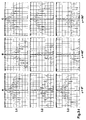
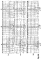
- FIG. 3 results from a first Sheet 3-I with the diagram lines 3.1 to 3.3 and a second sheet 3-II with the Diagram lines 3.4 to 3.6 are composed.
- the first diagram line 3.1 shows the normal sum signal which has a lower side lobe amplitude in the 45 ° plane according to column B than in the zx plane (column A) and in the zy plane (column C).
- the second line 3.2 shows the diagrams R HYPxz in the case of signal processing according to equation (9a) and line 3.3 the output direction finding signals R HYPyz according to equation (9b).
- P HYPyz shown in line 3.3, the situation is exactly the opposite.
- equation (12) compared to the normal sum signal (diagram line 3.1), there is now an improvement in the bundling and an increase in the sidelobe damping in all room levels (see Columns A, B, and C), while the directional characteristics in signal processing after the previous registration remain unaffected in the planes perpendicular to the main bundling planes.
- Directional diagram improvements are clearly shown in line 3.6, where both the bundling and the side lobe suppression are significantly improved.
- FIG. 4 shows an example of such a transducer arrangement in which two transducer group pairs are formed from the four transducer groups W LH , W LV , W RH and W RV , which are not oriented at right angles to one another.
- the main bundling planes here are the zx plane and a ⁇ z plane that is rotated by an angle ⁇ ⁇ 90 ° with respect to it and encloses the z axis.
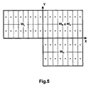
- two pairs of transducer groups can not only be formed from four transducer groups as previously described, but three identical transducer groups are sufficient for this.
- An example is shown in Fig. 5.
- the pairs of converter groups can be oriented at an angle ⁇ different from one another by 90 °.
- the application of the invention to a ship or submarine bearing on the side has the advantage that in addition to good focus sharpness in the optionally pivotable the main direction of the bearing also has a high side lobe suppression in the direction of travel including the plane, e.g. the screwing sound of your own Propeller does not affect the bearing.
- FIG. 6 A further embodiment of the invention is illustrated in FIG. 6.
- the ship is equipped here, for example, with a left converter group W L and a right converter group W R , which are oriented horizontally, that is, plumb down.
- Each transducer group consists of a plurality of transducer elements so that the main bearing direction can be pivoted in the transverse direction in a known manner by phase-staggered excitation and / or scanning.
- the two converter groups are arranged side by side in relation to the direction of travel F.
- a so-called synthetic aperture is first used, in which bearings along the travel path are carried out at predetermined spatial or temporal intervals ⁇ s or ⁇ t and the complex received signals Lsas and Rsas of the two converter groups W L and W R are temporarily stored.
- This known method in which the resulting aperture is considerably enlarged compared to the dimensions of the transducer arrangement and thus the bearing sharpness can be increased, is referred to as a sonar with a synthetic aperture SAS (Synthetic Aperture Sonar).
- the signals measured and buffered at certain path positions s i are then superimposed with a phase shift in order to generate a sharply bundled directional diagram in a plane including the direction of travel.
- the two complex output signals generated by SAS are used Lsas and Rsas of the left or right converter group combined analogously to equation (6), for example according to the following equation, to form a resulting output direction finding signal R HYPsas (n):
- the amount and phase of Lsas and Rsas available, ie the left and right SAS signals must be complex.
Landscapes
- Physics & Mathematics (AREA)
- Engineering & Computer Science (AREA)
- General Physics & Mathematics (AREA)
- Radar, Positioning & Navigation (AREA)
- Remote Sensing (AREA)
- Measurement Of Velocity Or Position Using Acoustic Or Ultrasonic Waves (AREA)
Abstract
Description
Die Erfindung geht von dem in der priortätsälteren, als WO 98/23970 am 04.06.1998
veröffentlichten EP-Patentanmeldung 97 951 196.1 beschriebenen Verfahren zur Richtstrahlbildung
in Peilanlagen aus, bei dem in einer elektronischen Signalverarbeitungseinrichtung einerseits aus
den Beträgen der komplexen Ausgangssignale zweier nebeneinander angeordneter, gleicher
Wandlergruppen ein Betrags-Summensignal sowie andererseits der Betrag der Differenz dieser
Wandler-Ausgangssignale gebildet und durch Differenz- oder Quotientenbildung aus diesen beiden
Betragssignalen ein Ausgangs-Peilsignal abgeleitet wird. Zu diesem Zweck sind zwei gleiche,
jeweils mindestens einen elektroakustischen oder elektromagnetischen Wandler (Antenne)
aufweisende Wandlergruppen vorgesehen und zu beiden Seiten einer Achse angeordnet. Jede
Wandlergruppe WL, WR erzeugt ein komplexes Ausgangssignal 



Mit der vorliegenden, in den unabhängigen Ansprüchen gekennzeichneten Erfindung werden
bevorzugte Weiterbildungen dieses Verfahrens zur Erzielung einer verbesserten räumlichen, also
dreidimensionalen Strahlbündelung aufgezeigt, d.h. zur Strahlbündelung in allen die
Hauptpeilrichtung einschließenden Ebenen. Vorteilhafte Ausgestaltungen der Erfindung ergeben
sich aus den Unteransprüchen. Die Erfindung wird nachfolgend anhand von Ausführungsbeispielen
aus dem Gebiet der Sonartechnik erläutert. In den Zeichnungen zeigt
Im Koordinatensystem nach Fig.1 weist die z-Achse in die gewünschte Hauptpeilrichtung, und die
Empfangsebene der hier als eben angenommenen Wandleranordnung liegt in der xy-Ebene. Um
eine räumliche Bündelung des Richtdiagramms zu erzielen, werden die Empfangssignale jeweils
zweier unter einem vorgegebenen Winkel ϕ , d.h. im Fall von ϕ = 90° rechtwinklig, zueinander
angeordneter gleicher Wandlergruppen der oben beschriebenen Signalverarbeitung unterworfen.
Bei der in Fig.2 in Draufsicht gezeigten Wandleranordnung mit vier Wandlergruppen WLV, WLH,
WRV und WRH sind dies zur Bündelung in der zx-Ebene die Signale der linken und rechten
Wandlergruppen und zur Bündelung in der zy-Ebene die Signale der vorderen und hinteren
Wandlergruppen. Die Indizes bedeuten L = links, R = rechts, V = vorn, H = hinten. Die als Beispiel
zur Erzeugung der in Fig.3 gezeigten Richtdiagramme verwendete und in Fig.2 gezeigte
Wandleranordnung besteht aus vier Gruppen von je 16 Wandlerelementen und hat in y-Richtung
eine Ausdehnung von 6 Wellenlängen λ und in x-Richtung von 8λ. Die von den vier
Wandlergruppen gelieferten komplexen Ausgangssignale werden mit
Die Bildung des Betrags-Summensignals RBSum und des Betrags-Differenzsignals RD erfolgt in der
zuvor beschriebenen Weise, d.h.




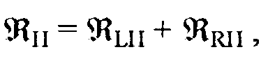




Will man die Bündelung gleichzeitig sowohl in der xz-Ebene als auch in der yz-Ebene sowie auch
in allen (vgl. Fig.1) dazwischen liegenden Ebenen, d.h. räumlich verbessern, so schlägt die
vorliegende Erfindung vor, die in den beiden Hauptbündelungsebenen nach obigen Gleichungen
gewonnenen gebündelten Richtdiagramme RHYPxz und RHYPyz miteinander zu verknüpfen, und zwar
beispielsweise durch eine spezielle Mittelwertbildung, durch geometrische Mittelwertbildung oder
multiplikativ. Im Falle einer solchen speziellen Mittelwertbildung erhält man ein resultierendes
dreidimensional gebündeltes Ausgangs-Peilsignal
Eine geometrische Mittelwertbildung führt nach der folgenden Gleichung zu einem ebenfalls
räumlich schärfer gebündelten Ausgangs-Peilsignal:
Schließlich kann man die in den beiden hier beispielsweise senkrecht zueinander stehenden und
jeweils die Hauptpeilrichtung einschließenden Hauptbündelungsebenen erzeugten, verbesserten
Richtdiagramme auch multiplikativ nach folgender Beziehung verknüpfen, um zu einer schärferen
räumlichen Bündelung zu kommen:
Im Prinzip sind auch andere Verknüpfungen der den beiden Hauptbündelungsebenen zugeordneten Ausgangssignale möglich und werden je nach den gestellten Anforderungen und den Randbedingungen des speziellen Anwendungsfalls ihre Vorteile entfalten. Das Wesentliche besteht darin, daß durch die gewählte Verknüpfung der nach den Gleichungen (9a) und (9b) gewonnenen Ausgangssignalwerte der beiden Hauptebenen eine gezielte Beeinflussung und Verbesserung des resultierenden räumlichen Richtdiagramms erreicht werden kann.In principle, other links are also assigned to the two main bundling levels Output signals possible and are depending on the requirements and the Boundary conditions of the special application unfold their advantages. The essentials consists in the fact that through the chosen combination of the equations (9a) and (9b) obtained output signal values of the two main levels a targeted influence and Improvement of the resulting spatial directional diagram can be achieved.
Zur Erläuterung dieser Verbesserungen wird auf Fig.3 verwiesen, welche sich aus einem ersten Blatt 3-I mit den Diagrammzeilen 3.1 bis 3.3 sowie einem zweiten Blatt 3-II mit den Diagrammzeilen 3.4 bis 3.6 zusammensetzt. In jeder Zeile zeigt das linke Diagramm A die Gestalt des Richtdiagramms in der zx-Ebene mit ϕ = 0°, das mittlere Diagramm B den Verlauf in der 45°-Ebene mit ϕ = 45° und das rechte Diagramm C die zy-Ebene mit ϕ = 90°, jeweils im logarithmischen Maßstab bis zu einer Dämpfung von -80dB. Diese Richtdiagramme wurden für eine Wandleranordnung nach Fig.2 berechnet.To explain these improvements, reference is made to FIG. 3, which results from a first Sheet 3-I with the diagram lines 3.1 to 3.3 and a second sheet 3-II with the Diagram lines 3.4 to 3.6 are composed. The left diagram A shows the shape in each line of the directional diagram in the zx plane with ϕ = 0 °, the middle diagram B shows the course in the 45 ° plane with ϕ = 45 ° and the right diagram C the zy-plane with ϕ = 90 °, each in logarithmic scale up to an attenuation of -80dB. These directional diagrams were created for calculated a converter arrangement according to Fig.2.
Die erste Diagrammzeile 3.1 zeigt das normale Summensignal

Zeile 3.4 zeigt die gemäß der Erfindung nach Gleichung (10) bei q = 2 und
Bislang wurde die räumliche Bündelung des Richtstrahls am Beispiel der Wandleranordnung von Fig.2 mit zwei rechtwinklig zueinander orientierten Wandlergruppenpaaren (ϕ = 90°) und somit für senkrecht aufeinender stehende Hauptbündelungsebenen (zx, zy) beschrieben. Dabei wurde ohne Einschränkung der Allgemeingültigkeit für die zx-Ebenene ϕ = 0 und für die zy-Ebenen ϕ = 90° definiert. Das Verfahren gemäß der Erfindung ist aber keineswegs auf rechtwinklig zueinander orientierte Wandlergruppenpaare beschränkt, sondern die Wandlergruppenpaare können auch unter einem anderen, von Null verschiedenenen Winkel ϕ zueinander orientiert sein. Es muß nur dafür gesorgt sein, daß sich gleiche Wandlergruppen und Wandlergruppenpaare ergehen. Die Gleichungen (8), (9a) und (9b) sowie die Verknüpfungsgleichungen (10), (11) und (12) sind dann sinngemäß anzuwenden. Geht man weiter davon aus, daß die erste Hauptbündelungsebene die zx-Ebene mit ϕ = 0 ist, so ist die zweite Hauptbündelungsebene nun nicht mehr um 90° sondern um einen beliebigen Winkel ϕ ≠ 90° um die z-Achse gedreht. Während RHYPxz gemäß Gleichung (9a) weiterhin das Ausgangssignal in der ersten Hauptbündelungsebene, nämlich der xz-Ebene ist, ist die zweite Hauptbündelungsebene nicht mehr die yz-Ebene mit ϕ = 90° sondern eine Zwischenebene, welche unter einem beliebigen Winkel 0 < ϕ < 90° gegenüber der xz-Ebene um die z-Achse gedreht ist und deshalb als ϕz-Ebene bezeichnet werden kann. Die Gleichung (9b) führt dann zu einem Ausgangssignal RHYPϕz in dieser zweiten Hauptbündelungsebene, welches dann gemäß den Gleichungen (10), (11) bzw. (12) anstelle von RHYPyz verarbeitet wird.So far, the spatial bundling of the directional beam has been described using the example of the transducer arrangement of FIG. 2 with two pairs of transducer groups oriented at right angles to one another (ϕ = 90 °) and thus for main bundling planes (zx, zy) that are perpendicular to one another. In doing so, the general validity was defined for the zx planes ϕ = 0 and for the zy planes ϕ = 90 °. However, the method according to the invention is by no means limited to pairs of transducers oriented at right angles to one another, but the pairs of transducers can also be oriented at another angle ϕ other than zero. It is only necessary to ensure that the same converter groups and pairs of converter groups occur. Equations (8), (9a) and (9b) and the linking equations (10), (11) and (12) are then to be applied accordingly. If one further assumes that the first main bundling plane is the zx plane with ϕ = 0, the second main bundling plane is no longer rotated by 90 ° but by any angle ϕ ≠ 90 ° around the z axis. While R HYPxz according to equation (9a) continues to be the output signal in the first main bundling plane, namely the xz plane, the second main bundling plane is no longer the yz plane with ϕ = 90 ° but an intermediate plane which is at any angle 0 <ϕ <90 ° with respect to the xz plane around the z axis and can therefore be referred to as the bezeichnetz plane. Equation (9b) then leads to an output signal R HYPϕz in this second main bundling level , which is then processed in accordance with equations (10), (11) and (12) instead of R HYPyz .
Fig.4 zeigt ein Beispiel einer solchen Wandleranordnung, bei der aus den vier Wandlergruppen WLH, WLV, WRH und WRV zwei Wandlergruppenpaare gebildet sind, die nicht rechtwinklig zueinander orientiert sind. Die Hauptbündelungsebenen sind hier die zx-Ebene und eine gegenüber dieser um den Winkel ϕ ≠ 90° gedrehte, die z-Achse einschließende ϕz-Ebene.4 shows an example of such a transducer arrangement in which two transducer group pairs are formed from the four transducer groups W LH , W LV , W RH and W RV , which are not oriented at right angles to one another. The main bundling planes here are the zx plane and a ϕz plane that is rotated by an angle ϕ ≠ 90 ° with respect to it and encloses the z axis.
Zur räumlichen Bündelung der Richtstrahls lassen sich zwei Wandlergruppenpaare nicht nur, wie
bisher beschrieben aus vier Wandlergruppen bilden, sondern es genügen hierfür schon drei gleiche
Wandlergruppen. Ein Beispiel zeigt Fig.5. Die komplexen Ausgangssignale 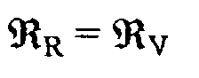
Die mit der Erfindung erzielbare Verbesserung der Richtcharakteristik gilt auch für Richtdiagramme, deren Hauptpeilrichtung durch phasenversetzte Ansteuerung oder Abtastung der Wandler in den einzelnen Wandlergruppen geschwenkt wird.The improvement in the directional characteristic that can be achieved with the invention also applies to Directional diagrams, the main bearing direction by phase-shifted control or scanning of Converter is pivoted in the individual converter groups.
Die Anwendung der Erfindung bei einem seitlich peilenden Schiff oder U-Boot hat beispielsweise den Vorteil, daß neben einer guten Bündelungsschärfe in der gegebenenfalls schwenkbaren seitlichen Hauptpeilrichtung auch eine hohe Nebenkeulen-Unterdrückung in der die Fahrtrichtung einschließenden Ebene erzielt wird, so daß z.B. das Schraubengeräusch der eigenen Schiffsschraube die Peilung nicht beeinträchtigt.For example, the application of the invention to a ship or submarine bearing on the side has the advantage that in addition to good focus sharpness in the optionally pivotable the main direction of the bearing also has a high side lobe suppression in the direction of travel including the plane, e.g. the screwing sound of your own Propeller does not affect the bearing.
Eine weitere Ausgestaltung der Erfindung veranschaulicht Fig.6. Das Schiff ist hier beispielsweise
mit einer linken Wandlergruppe WL und einer rechten Wandlergruppe WR ausgestattet, welche
horizontal ausgerichtet sind, also nach unten loten. Jede Wandlergruppe besteht aus mehreren
Wandlerelementen, damit die Hauptpeilrichtung in bekannter Weise durch phasengestaffelte
Erregung und/oder Abtastung in Querabrichtung geschwenkt werden kann. Die beiden
Wandlergruppen sind, bezogen aufdie Fahrtrichtung F nebeneinander angeordnet. Durch
Anwendung der Gleichung (9a) des Hauptpatents erzielt man unterhalb des Schiffes und seitlich
geschwenkt eine Bündelungsverbesserung in der sich quer zur Fahrtrichtung F erstreckenden
Vertikalebene. Um eine Bündelung auch in den die Fahrtrichtung F einschließenden Ebenen zu
erzeugen, wird hier zunächst eine sogenannte synthetische Apertur angewandt, bei der längs des
Fahrtweges in vorgegebenen räumlichen oder zeitlichen Abständen Δs bzw. Δt Peilungen
durchgeführt und die komplexen Empfangssignale 
Claims (9)








Applications Claiming Priority (2)
| Application Number | Priority Date | Filing Date | Title |
|---|---|---|---|
| DE19822445 | 1998-05-19 | ||
| DE1998122445 DE19822445A1 (en) | 1996-11-22 | 1998-05-19 | Method of spatial directional beam formation in direction-finding system |
Publications (2)
| Publication Number | Publication Date |
|---|---|
| EP0959367A2 true EP0959367A2 (en) | 1999-11-24 |
| EP0959367A3 EP0959367A3 (en) | 2000-08-02 |
Family
ID=7868290
Family Applications (1)
| Application Number | Title | Priority Date | Filing Date |
|---|---|---|---|
| EP99109603A Withdrawn EP0959367A3 (en) | 1998-05-19 | 1999-05-14 | Method for the spatial transformation of radiated beams in direction finder systems |
Country Status (2)
| Country | Link |
|---|---|
| US (1) | US6178140B1 (en) |
| EP (1) | EP0959367A3 (en) |
Cited By (1)
| Publication number | Priority date | Publication date | Assignee | Title |
|---|---|---|---|---|
| WO2010135465A1 (en) * | 2009-05-19 | 2010-11-25 | Arsen Melconian | Systems and methods for tracking a remote source and orientation control |
Families Citing this family (15)
| Publication number | Priority date | Publication date | Assignee | Title |
|---|---|---|---|---|
| US7372402B2 (en) | 2002-08-30 | 2008-05-13 | Telfonaktiebolaget Lm Ericsson (Publ) | Method for enhancing the measuring accuracy in an antenna array |
| AU2002330818A1 (en) * | 2002-08-30 | 2004-03-19 | Telefonaktiebolaget L M Ericsson (Publ) | Reduction of near ambiguities |
| KR100689514B1 (en) * | 2006-01-23 | 2007-03-02 | 주식회사 하이닉스반도체 | Semiconductor element and manufacturing method thereof |
| WO2013039355A2 (en) * | 2011-09-15 | 2013-03-21 | Samsung Electronics Co., Ltd. | Apparatus and method for beam selecting in beamformed wireless communication system |
| US10193397B2 (en) | 2015-04-10 | 2019-01-29 | Ossia Inc. | Establishing connections with chargers in multi-charger wireless power delivery environments |
| WO2016164790A1 (en) | 2015-04-10 | 2016-10-13 | Ossia Inc. | Wireless power transceivers for supplementing wireless power delivery and extending range |
| US10559971B2 (en) | 2015-04-10 | 2020-02-11 | Ossia Inc. | Wirelessly chargeable battery apparatus |
| US10177607B2 (en) | 2015-04-10 | 2019-01-08 | Ossia Inc. | Techniques for delivering retrodirective wireless power |
| US9971015B2 (en) | 2015-04-10 | 2018-05-15 | Ossia Inc. | Techniques for imaging wireless power delivery environments and tracking objects therein |
| US10079494B2 (en) | 2015-04-10 | 2018-09-18 | Ossia Inc. | Removably attachable portable device apparatus with integrated wireless power receiving facilities |
| JP2018536372A (en) | 2015-10-15 | 2018-12-06 | オシア,インク. | Concentration method of pulsed transmission in multipath wireless power supply environment |
| US11146093B2 (en) | 2017-03-31 | 2021-10-12 | Ossia Inc. | Actively modifying output voltage of a wirelessly chargeable energy storage apparatus |
| US10418861B2 (en) | 2017-12-22 | 2019-09-17 | Ossia Inc. | Transmission path identification based on propagation channel diversity |
| EP3809526A1 (en) | 2019-10-18 | 2021-04-21 | Rohde & Schwarz GmbH & Co. KG | Antenna system and antenna controlling method |
| US12046910B2 (en) | 2020-02-24 | 2024-07-23 | Ossia Inc. | Devices and systems for providing wirelessly chargeable batteries with improved charge capacities |
Family Cites Families (4)
| Publication number | Priority date | Publication date | Assignee | Title |
|---|---|---|---|---|
| JPH0748616B2 (en) | 1991-10-24 | 1995-05-24 | 宇宙開発事業団 | Antenna pattern processing method |
| US5248984A (en) | 1991-11-13 | 1993-09-28 | National Space Development Agency Of Japan | Method for processing an antenna pattern |
| JPH06331720A (en) * | 1993-05-26 | 1994-12-02 | Toyota Central Res & Dev Lab Inc | Monopulse antenna |
| DE19648327B4 (en) | 1996-11-22 | 2004-03-18 | L-3 Communications Elac Nautik Gmbh | Method for directional beam formation in DF systems and device for carrying out the method |
-
1999
- 1999-03-24 US US09/275,650 patent/US6178140B1/en not_active Expired - Lifetime
- 1999-05-14 EP EP99109603A patent/EP0959367A3/en not_active Withdrawn
Cited By (2)
| Publication number | Priority date | Publication date | Assignee | Title |
|---|---|---|---|---|
| WO2010135465A1 (en) * | 2009-05-19 | 2010-11-25 | Arsen Melconian | Systems and methods for tracking a remote source and orientation control |
| US7999738B2 (en) | 2009-05-19 | 2011-08-16 | Arsen Melconian | Systems and methods for tracking a remote source and orientation control |
Also Published As
| Publication number | Publication date |
|---|---|
| US6178140B1 (en) | 2001-01-23 |
| EP0959367A3 (en) | 2000-08-02 |
Similar Documents
| Publication | Publication Date | Title |
|---|---|---|
| DE2402050C3 (en) | Device for improving the signal-to-noise ratio of signals received by several antennas | |
| DE69930384T2 (en) | ADAPTIVE GROUP ANTENNA | |
| DE60302379T2 (en) | Radar processing system and method for detecting and monitoring targets | |
| DE19581713B4 (en) | Baseband processor for processing signals from ultrasound receive beam-former - has complex response adjuster which operates on samples to effect phase and amplitude coherence between samples | |
| DE69402084T2 (en) | SONAR SYSTEM FOR FLOW SPEED METER AND DOPPLER LOG | |
| DE69812783T2 (en) | Group antenna with interference protection | |
| DE3110532C2 (en) | ||
| DE3411135C2 (en) | Phased ultrasound imaging system | |
| DE69022926T2 (en) | Virtual microphone system and the procedure for it. | |
| DE69819273T2 (en) | Antenna formed by a variety of acoustic detectors | |
| DE2945830C2 (en) | Directional antenna system for friend-foe identification or direction finding | |
| DE102013203789A1 (en) | Antenna arrangement with variable directional characteristics | |
| DE19648327B4 (en) | Method for directional beam formation in DF systems and device for carrying out the method | |
| EP2145203A1 (en) | Method for locating a sound-projecting target | |
| DE19627218B4 (en) | radar device | |
| EP1285554A2 (en) | Directional microphone arrangement and method for signal processing in a directional microphone arrangement | |
| DE19503374B4 (en) | Passive sound transducer arrangement | |
| DE19822445A1 (en) | Method of spatial directional beam formation in direction-finding system | |
| DE102010056526B4 (en) | Method for determining one or more relative directions as target bearing or target bearings and device for carrying out the method | |
| DE10353292B3 (en) | Method of forming a group signal | |
| EP3082273B1 (en) | Method and device for reduction of correlated interference in multichannel receiver systems correlated with digital beam forming | |
| DE4039153B4 (en) | Method and device for generating a radiation pattern at rest in a group antenna | |
| DE60133222T2 (en) | INTERFEROMETIC SYNTHETIC SONARANTENNE | |
| EP2145204B1 (en) | Method for taking bearings of sound-emitting targets, and bearing system | |
| EP1391750A2 (en) | Method for estimating the geometry of an acoustic linear antenna. |
Legal Events
| Date | Code | Title | Description |
|---|---|---|---|
| PUAI | Public reference made under article 153(3) epc to a published international application that has entered the european phase |
Free format text: ORIGINAL CODE: 0009012 |
|
| AK | Designated contracting states |
Kind code of ref document: A2 Designated state(s): DE FR GB IT |
|
| AX | Request for extension of the european patent |
Free format text: AL;LT;LV;MK;RO;SI |
|
| PUAL | Search report despatched |
Free format text: ORIGINAL CODE: 0009013 |
|
| AK | Designated contracting states |
Kind code of ref document: A3 Designated state(s): AT BE CH CY DE DK ES FI FR GB GR IE IT LI LU MC NL PT SE |
|
| AX | Request for extension of the european patent |
Free format text: AL;LT;LV;MK;RO;SI |
|
| 17P | Request for examination filed |
Effective date: 20010118 |
|
| AKX | Designation fees paid |
Free format text: DE FR GB IT |
|
| 17Q | First examination report despatched |
Effective date: 20020410 |
|
| STAA | Information on the status of an ep patent application or granted ep patent |
Free format text: STATUS: THE APPLICATION HAS BEEN WITHDRAWN |
|
| 18W | Application withdrawn |
Effective date: 20021210 |