EP0959277A2 - A seal device - Google Patents
A seal device Download PDFInfo
- Publication number
- EP0959277A2 EP0959277A2 EP99850040A EP99850040A EP0959277A2 EP 0959277 A2 EP0959277 A2 EP 0959277A2 EP 99850040 A EP99850040 A EP 99850040A EP 99850040 A EP99850040 A EP 99850040A EP 0959277 A2 EP0959277 A2 EP 0959277A2
- Authority
- EP
- European Patent Office
- Prior art keywords
- seal
- pump
- spring housing
- seal device
- circulation
- Prior art date
- Legal status (The legal status is an assumption and is not a legal conclusion. Google has not performed a legal analysis and makes no representation as to the accuracy of the status listed.)
- Granted
Links
Images

Classifications
-
- F—MECHANICAL ENGINEERING; LIGHTING; HEATING; WEAPONS; BLASTING
- F16—ENGINEERING ELEMENTS AND UNITS; GENERAL MEASURES FOR PRODUCING AND MAINTAINING EFFECTIVE FUNCTIONING OF MACHINES OR INSTALLATIONS; THERMAL INSULATION IN GENERAL
- F16J—PISTONS; CYLINDERS; SEALINGS
- F16J15/00—Sealings
- F16J15/16—Sealings between relatively-moving surfaces
- F16J15/34—Sealings between relatively-moving surfaces with slip-ring pressed against a more or less radial face on one member
- F16J15/3404—Sealings between relatively-moving surfaces with slip-ring pressed against a more or less radial face on one member and characterised by parts or details relating to lubrication, cooling or venting of the seal
-
- F—MECHANICAL ENGINEERING; LIGHTING; HEATING; WEAPONS; BLASTING
- F16—ENGINEERING ELEMENTS AND UNITS; GENERAL MEASURES FOR PRODUCING AND MAINTAINING EFFECTIVE FUNCTIONING OF MACHINES OR INSTALLATIONS; THERMAL INSULATION IN GENERAL
- F16J—PISTONS; CYLINDERS; SEALINGS
- F16J15/00—Sealings
- F16J15/16—Sealings between relatively-moving surfaces
- F16J15/34—Sealings between relatively-moving surfaces with slip-ring pressed against a more or less radial face on one member
- F16J15/3464—Mounting of the seal
- F16J15/348—Pre-assembled seals, e.g. cartridge seals
- F16J15/3484—Tandem seals
Definitions
- the present invention concerns a device for a submersible machine, such as a pump, a turbine or a mixer.
- a machine of this type normally includes an electrically driven motor and a hydraulic unit with an impeller connected to the motor via a rotary driving shaft.
- one or several seals are arranged between the motor and the hydraulic unit.
- a common type of seal is the so-called mechanical face seal, which comprises one seal ring rotating with the shaft and one stationary seal ring mounted in the surrounding housing. The two rings are pressed together by spring force thus preventing medium from penetrating between them.
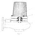
- Fig 1 shows a cut through a pump unit provided with a seal arrangement according to the invention
- Fig 2 is a principle sketch of the seal device with an integrated pump.
- FIG. 1 stands for a motor unit, 2 a hydraulic unit and 3 a driving shaft between the two.
- 4 and 5 stand for rotary seal rings, 6 and 7 stationary seal rings.
- 8 and 9 stand for springs, 10 a spring housing, 11 and 12 drivers, 13 and 14 holders for the stationary seal rings 6 and 7.
- 15 stands for stationary vanes, 16 an impeller vane, 17 a channel for medium, 18 o-rings and 19 a shoulder on the shaft 3.
- the driving shaft 3 between the motor 1 and the hydraulic unit 2 is thus sealed-off by two mechanical face seals, 4,6 and 5,7 resp.
- the first, called the outer seal is located close to the hydraulic unit, while the second, called the inner seal, is located close to the motor.
- the seal rings 4 and 5 rotate with the shaft and are presed towards the stationary seal rings 6 and 7 resp. by spring force. In this way the medium within the hydraulic unit is effectively prevented from passing the seal area and penetrate the motor.
- the seal device is designed as an easily replaceable unit. Said unit is slid onto the shaft 3 until it reaches a position decided by a shoulder 19 on the shaft, which shoulder supports the rotary seal ring 4 of the outer seal. Said replaceable unit includes the seals 4,6 and 5, 7, a uniting spring housing 10 and holders 13 and 14 for the stationary seal rings 6 and 7.
- the spring housing 10 is attached to the rotary seal ring 4 of the outer seal by help of snap-in means 11. As the seal ring 4 is in alignment with the shoulder 19 on the shaft 3, the spring housing will also be locked on the shaft and is prevented from moving in the direction of the motor 1. Said spring housing is also provided with a driver 12 for the rotary seal ring 5 of the inner seal and provides a seat for the spring means 9 which urges said ring towards the stationary ring 7 of said inner seal. Thanks to this design of the spring housing, a compact unit is obtained which has a minimum axial extension.
- the seal unit also includes means for providing a circulation of the barrier medium, which medium also may be used as a coolant for the motor.
- the spring housing 10 constitutes a hub for a number of impeller vanes 16 which rotate in an axial pump housing created by the holders 13 and 14 for the stationary seal rings 6 and 7 resp. Said holders being connected by means 15 which simultanously act as stationary vanes in said pump housing.
- a seal device designed as a compact unit is obtained, which is easy to exchange in the machine where it is operating and which is easy to mount to a well-defined position on the driving shaft thanks to the shoulder mentioned.
- the unit includes a pump for circulation of the barrier medium within the seal, which medium also may serve as a coolant for the motor.
Abstract
Description
- The present invention concerns a device for a submersible machine, such as a pump, a turbine or a mixer.
- A machine of this type normally includes an electrically driven motor and a hydraulic unit with an impeller connected to the motor via a rotary driving shaft.
In order to prevent the medium within the hydraulic unit from flowing along the shaft and penetrate the electric motor and cause damage, one or several seals are arranged between the motor and the hydraulic unit. A common type of seal is the so-called mechanical face seal, which comprises one seal ring rotating with the shaft and one stationary seal ring mounted in the surrounding housing. The two rings are pressed together by spring force thus preventing medium from penetrating between them. - If the medium within the hydraulic unit contains pollutants, a special problem occurs. As the pressure within the hydraulic unit is higher, pollutants may penetrate between the seal surfaces an cause damage, meaning that the seal result deteriorates or fails totally.
- In order to solve this problem it is common to arrange two mechanical seals with an intermediate room filled with a barrier liquid such as oil, which lubricates and cools the surfaces. By this the seal adjacent the electric motor will always operate with a clean medium and thus the risks for damages will decrease drastically. If the seal adjacent the hydraulic unit should be damaged, medium from said unit may enter the barrier liquid room, but by controlling said liquid at regular intervals, the seal could be repaired or replaced before any serious damage has occurred. An example on such a design is shown in the Swedish patent No 381 318.
- If it has been noted that the barrier liquid has been too diluted by the medium in the hydraulic unit, the seal adjacent said unit must be replaced. If the dilution has been considerable, there is a risk that also the other seal has been damaged and therefore it might be preferable to replace both seals at the same time.
- In order to make such a replacement easier, it has been suggested to arrange them in one single unit which makes service easier and increases the reliability. Examples on such designs are shown in the Swedish patents 200 144 and 466 925.
- In order to obtain a good circulation of the barrier liquid within the seal unit, it has been suggested to arrange a pump within the latter. Especially in a case where it has been chosen to use a closed cooling system for the electric motor using the barrier liguid as a coolant, a pump is necessary if a sufficient flow should be obtained.
- Known designs such as those shown in the Swedish patent 327 904 have however certain disadvantages concerning space demand and efficiency. This invention concerns a device which in an effective and secure way obtains the necessary circulation even at a low rotation speed and which has a very limited space demand.
- The invention is disclosed more closely below with reference to the enclosed drawings. Fig 1 shows a cut through a pump unit provided with a seal arrangement according to the invention, while Fig 2 is a principle sketch of the seal device with an integrated pump.
- In the drawings 1 stands for a motor unit, 2 a hydraulic unit and 3 a driving shaft between the two. 4 and 5 stand for rotary seal rings, 6 and 7 stationary seal rings. 8 and 9 stand for springs, 10 a spring housing, 11 and 12 drivers, 13 and 14 holders for the
stationary seal rings shaft 3. - The
driving shaft 3 between the motor 1 and thehydraulic unit 2 is thus sealed-off by two mechanical face seals, 4,6 and 5,7 resp. The first, called the outer seal, is located close to the hydraulic unit, while the second, called the inner seal, is located close to the motor. - The seal rings 4 and 5 rotate with the shaft and are presed towards the
stationary seal rings - As previously mentioned, the seal device is designed as an easily replaceable unit. Said unit is slid onto the
shaft 3 until it reaches a position decided by a shoulder 19 on the shaft, which shoulder supports therotary seal ring 4 of the outer seal. Said replaceable unit includes theseals spring housing 10 andholders stationary seal rings - The
spring housing 10 is attached to therotary seal ring 4 of the outer seal by help of snap-in means 11. As theseal ring 4 is in alignment with the shoulder 19 on theshaft 3, the spring housing will also be locked on the shaft and is prevented from moving in the direction of the motor 1. Said spring housing is also provided with adriver 12 for therotary seal ring 5 of the inner seal and provides a seat for the spring means 9 which urges said ring towards thestationary ring 7 of said inner seal. Thanks to this design of the spring housing, a compact unit is obtained which has a minimum axial extension. - As previously mensioned, the seal unit also includes means for providing a circulation of the barrier medium, which medium also may be used as a coolant for the motor. In order to obtain this circulation, the
spring housing 10 constitutes a hub for a number ofimpeller vanes 16 which rotate in an axial pump housing created by theholders stationary seal rings means 15 which simultanously act as stationary vanes in said pump housing. - According to the invention, a seal device designed as a compact unit is obtained, which is easy to exchange in the machine where it is operating and which is easy to mount to a well-defined position on the driving shaft thanks to the shoulder mentioned. The unit includes a pump for circulation of the barrier medium within the seal, which medium also may serve as a coolant for the motor.
Claims (1)
- A seal device in the form of an easily exchangeable unit for a rotary driving shaft, preferably a driving shaft (3) between an electric motor (1) and a pump impeller or a propeller in a submersible pump or mixer, the seal device comprising two mechanical face seals (4,6) and (5,7) resp. with an intermediate room for barrier liquid and a pump for circulation of said barrier liquid, characterized in, that the seal device comprises a cylindric spring housing (10) rotating with the shaft (3), said spring housing being connected to the rotary seal ring (4) of one of the mechanical face seals by help of a means (11), that said spring housing is provided with means (12) for driving the rotary seal ring (5) of said other mechanical face seal, that said spring housing constitutes a seat for a spring means (9) which urges said seal ring (5) towards said stationary seal ring (7) and that said spring housing is the hub for vanes (16) in said pump for circulation of said barrier liquid, the outer pump housing wall of said pump being formed by holders (13) and (14) for the stationary seal rings (6) and (7) resp.
Applications Claiming Priority (2)
| Application Number | Priority Date | Filing Date | Title |
|---|---|---|---|
| SE9801731 | 1998-05-18 | ||
| SE9801731A SE521394C2 (en) | 1998-05-18 | 1998-05-18 | Sealing device for a submersible work machine |
Publications (3)
| Publication Number | Publication Date |
|---|---|
| EP0959277A2 true EP0959277A2 (en) | 1999-11-24 |
| EP0959277A3 EP0959277A3 (en) | 2000-08-09 |
| EP0959277B1 EP0959277B1 (en) | 2004-04-14 |
Family
ID=20411345
Family Applications (1)
| Application Number | Title | Priority Date | Filing Date |
|---|---|---|---|
| EP99850040A Expired - Lifetime EP0959277B1 (en) | 1998-05-18 | 1999-03-18 | An arrangement comprising a rotary shaft and a seal device |
Country Status (13)
| Country | Link |
|---|---|
| US (1) | US6446975B1 (en) |
| EP (1) | EP0959277B1 (en) |
| JP (1) | JP4256011B2 (en) |
| AT (1) | ATE264471T1 (en) |
| AU (1) | AU743073B2 (en) |
| BR (1) | BR9902588A (en) |
| CA (1) | CA2272171C (en) |
| DE (1) | DE69916362T2 (en) |
| DK (1) | DK0959277T3 (en) |
| ES (1) | ES2220031T3 (en) |
| PT (1) | PT959277E (en) |
| SE (1) | SE521394C2 (en) |
| ZA (1) | ZA991531B (en) |
Cited By (3)
| Publication number | Priority date | Publication date | Assignee | Title |
|---|---|---|---|---|
| EP1148277A3 (en) * | 2000-02-26 | 2003-05-14 | S.I.T Schiffs-& Industrie Technik GmbH | Method and device for the reduction of oil-cake formation in oil containing apparatus |
| US8491277B2 (en) | 2010-02-12 | 2013-07-23 | Ebara Corporation | Submersible motor pump, motor pump, and tandem mechanical seal |
| CN111486124A (en) * | 2020-04-17 | 2020-08-04 | 中山市睿普自动化科技有限公司 | Mechanical sealing device for leakage prevention of pump body |
Families Citing this family (14)
| Publication number | Priority date | Publication date | Assignee | Title |
|---|---|---|---|---|
| SE518107C2 (en) * | 2000-08-23 | 2002-08-27 | Itt Mfg Enterprises Inc | Sealing and cooling device for a submersible working machine, for example a pump or stirrer |
| WO2002027197A2 (en) * | 2000-09-29 | 2002-04-04 | A.W. Chesterton Company | Spacing element for centering components in a mechanical seal and for promoting circulation of a seal fluid therein |
| SE531613C2 (en) * | 2005-06-27 | 2009-06-09 | Huhnseal Ab | sealing device |
| CN100458177C (en) * | 2006-08-29 | 2009-02-04 | 上海市化工装备研究所 | Built-in type parking sealing arrangement |
| TWM348160U (en) * | 2008-06-02 | 2009-01-01 | Cheng-Chin Kung | Shaft seal of pump |
| JP5478290B2 (en) * | 2010-02-12 | 2014-04-23 | 株式会社荏原製作所 | Tandem mechanical seal |
| JP5712067B2 (en) * | 2011-06-27 | 2015-05-07 | 株式会社日立製作所 | High temperature fluid shaft seal device |
| USD881365S1 (en) | 2018-02-28 | 2020-04-14 | S. C. Johnson & Son, Inc. | Dispenser |
| USD880670S1 (en) | 2018-02-28 | 2020-04-07 | S. C. Johnson & Son, Inc. | Overcap |
| USD872847S1 (en) | 2018-02-28 | 2020-01-14 | S. C. Johnson & Son, Inc. | Dispenser |
| USD872245S1 (en) | 2018-02-28 | 2020-01-07 | S. C. Johnson & Son, Inc. | Dispenser |
| USD852938S1 (en) | 2018-05-07 | 2019-07-02 | S. C. Johnson & Son, Inc. | Dispenser |
| USD853548S1 (en) | 2018-05-07 | 2019-07-09 | S. C. Johnson & Son, Inc. | Dispenser |
| US11021982B2 (en) * | 2018-09-28 | 2021-06-01 | Hamilton Sundstrand Corporation | Shaft face seal |
Citations (2)
| Publication number | Priority date | Publication date | Assignee | Title |
|---|---|---|---|---|
| SE200144C1 (en) | ||||
| SE327904B (en) | 1969-04-18 | 1970-08-31 | Stenberg Flygt Ab |
Family Cites Families (10)
| Publication number | Priority date | Publication date | Assignee | Title |
|---|---|---|---|---|
| DE7110850U (en) * | 1971-07-15 | Sonesson Pumpindustri Ab | Device for maintaining a certain pressure in the pressure chamber of a pump, which is filled with blocking medium | |
| US2628852A (en) * | 1949-02-02 | 1953-02-17 | Crane Packing Co | Cooling system for double seals |
| US3489419A (en) * | 1967-11-01 | 1970-01-13 | King Of Prussia Research & Dev | Static pressure system for mechanical seals |
| FR2008305A1 (en) * | 1968-05-11 | 1970-01-16 | Emu Unterwasserpumpen | |
| FR2016621A1 (en) * | 1968-08-30 | 1970-05-08 | Goeppner Kaiserslautern Eisen | |
| BE747755A (en) * | 1970-03-20 | 1970-08-31 | Sussmeyer Louis | WATERPROOFING AND GUIDING DEVICE FOR A WINDING DRIVEN SHAFT, |
| CH572174A5 (en) * | 1972-06-09 | 1976-01-30 | Burgmann Dichtungswerk Feodor | |
| DE2408660C3 (en) * | 1974-02-22 | 1979-08-23 | Feodor Burgmann Dichtungswerk, 8190 Wolfratshausen | Double acting mechanical seal |
| US4361334A (en) * | 1980-11-20 | 1982-11-30 | The Pfaudler Co. Inc. | Compression sealed composite seal seat with cooling passages |
| US5238253A (en) * | 1991-04-22 | 1993-08-24 | Roy E. Roth Company | Regenerative turbine flow inducer for double or tandem mechanical seals |
-
1998
- 1998-05-18 SE SE9801731A patent/SE521394C2/en not_active IP Right Cessation
-
1999
- 1999-02-09 US US09/246,321 patent/US6446975B1/en not_active Expired - Lifetime
- 1999-02-18 BR BR9902588-4A patent/BR9902588A/en not_active IP Right Cessation
- 1999-02-25 ZA ZA9901531A patent/ZA991531B/en unknown
- 1999-03-18 ES ES99850040T patent/ES2220031T3/en not_active Expired - Lifetime
- 1999-03-18 EP EP99850040A patent/EP0959277B1/en not_active Expired - Lifetime
- 1999-03-18 JP JP07303999A patent/JP4256011B2/en not_active Expired - Lifetime
- 1999-03-18 DE DE69916362T patent/DE69916362T2/en not_active Expired - Lifetime
- 1999-03-18 DK DK99850040T patent/DK0959277T3/en active
- 1999-03-18 AT AT99850040T patent/ATE264471T1/en not_active IP Right Cessation
- 1999-03-18 PT PT99850040T patent/PT959277E/en unknown
- 1999-05-03 AU AU26914/99A patent/AU743073B2/en not_active Expired
- 1999-05-17 CA CA002272171A patent/CA2272171C/en not_active Expired - Lifetime
Patent Citations (2)
| Publication number | Priority date | Publication date | Assignee | Title |
|---|---|---|---|---|
| SE200144C1 (en) | ||||
| SE327904B (en) | 1969-04-18 | 1970-08-31 | Stenberg Flygt Ab |
Cited By (3)
| Publication number | Priority date | Publication date | Assignee | Title |
|---|---|---|---|---|
| EP1148277A3 (en) * | 2000-02-26 | 2003-05-14 | S.I.T Schiffs-& Industrie Technik GmbH | Method and device for the reduction of oil-cake formation in oil containing apparatus |
| US8491277B2 (en) | 2010-02-12 | 2013-07-23 | Ebara Corporation | Submersible motor pump, motor pump, and tandem mechanical seal |
| CN111486124A (en) * | 2020-04-17 | 2020-08-04 | 中山市睿普自动化科技有限公司 | Mechanical sealing device for leakage prevention of pump body |
Also Published As
| Publication number | Publication date |
|---|---|
| AU743073B2 (en) | 2002-01-17 |
| ES2220031T3 (en) | 2004-12-01 |
| DE69916362D1 (en) | 2004-05-19 |
| DE69916362T2 (en) | 2005-05-04 |
| AU2691499A (en) | 1999-11-25 |
| ATE264471T1 (en) | 2004-04-15 |
| ZA991531B (en) | 1999-08-26 |
| SE521394C2 (en) | 2003-10-28 |
| PT959277E (en) | 2004-08-31 |
| SE9801731D0 (en) | 1998-05-18 |
| US6446975B1 (en) | 2002-09-10 |
| JP4256011B2 (en) | 2009-04-22 |
| CA2272171C (en) | 2004-01-20 |
| EP0959277A3 (en) | 2000-08-09 |
| BR9902588A (en) | 2000-02-22 |
| DK0959277T3 (en) | 2004-07-26 |
| EP0959277B1 (en) | 2004-04-14 |
| CA2272171A1 (en) | 1999-11-18 |
| SE9801731L (en) | 1999-11-19 |
| JPH11325258A (en) | 1999-11-26 |
Similar Documents
| Publication | Publication Date | Title |
|---|---|---|
| CA2272171C (en) | Seal arrangement | |
| US5553867A (en) | Triple cartridge seal having one inboard and two concentric seals for chemical processing pump | |
| EP0252037A1 (en) | A seal device | |
| EP0939231B1 (en) | A seal device | |
| CN100385154C (en) | Pressure resistant static and dynamic expeller shaft sealing | |
| JPH10184580A (en) | Rotary fluid pump | |
| EP0940611B1 (en) | A pump sealing device | |
| EP0843115B1 (en) | A seal system for submersible machines comprising an electric motor/generator | |
| EP1182354B1 (en) | A machine comprising a sealing and cooling device | |
| EP0388384B1 (en) | Mechanical seal | |
| US5181729A (en) | Seal device | |
| EP0774584B1 (en) | A device for mounting and keeping together parts in a submersible pump unit | |
| EP0490846A1 (en) | Submersible machine | |
| EP1637782A1 (en) | Seal housing for a mechanical seal | |
| RU2749243C1 (en) | Sealing device, hydrodynamic machine and vehicle | |
| EP1001195A1 (en) | Seal assembly in particular for a turbo generator |
Legal Events
| Date | Code | Title | Description |
|---|---|---|---|
| PUAI | Public reference made under article 153(3) epc to a published international application that has entered the european phase |
Free format text: ORIGINAL CODE: 0009012 |
|
| AK | Designated contracting states |
Kind code of ref document: A2 Designated state(s): AT CH DE DK ES FI FR GB IE IT LI NL PT |
|
| AX | Request for extension of the european patent |
Free format text: AL;LT;LV;MK;RO;SI |
|
| PUAL | Search report despatched |
Free format text: ORIGINAL CODE: 0009013 |
|
| AK | Designated contracting states |
Kind code of ref document: A3 Designated state(s): AT BE CH CY DE DK ES FI FR GB GR IE IT LI LU MC NL PT SE |
|
| AX | Request for extension of the european patent |
Free format text: AL;LT;LV;MK;RO;SI |
|
| 17P | Request for examination filed |
Effective date: 20001002 |
|
| AKX | Designation fees paid |
Free format text: AT CH DE DK ES FI FR GB IE IT LI NL PT |
|
| 17Q | First examination report despatched |
Effective date: 20030319 |
|
| RTI1 | Title (correction) |
Free format text: AN ARRANGEMENT COMPRISING A ROTARY SHAFT AND A SEAL DEVICE |
|
| RTI1 | Title (correction) |
Free format text: AN ARRANGEMENT COMPRISING A ROTARY SHAFT AND A SEAL DEVICE |
|
| GRAP | Despatch of communication of intention to grant a patent |
Free format text: ORIGINAL CODE: EPIDOSNIGR1 |
|
| GRAS | Grant fee paid |
Free format text: ORIGINAL CODE: EPIDOSNIGR3 |
|
| GRAA | (expected) grant |
Free format text: ORIGINAL CODE: 0009210 |
|
| AK | Designated contracting states |
Kind code of ref document: B1 Designated state(s): AT CH DE DK ES FI FR GB IE IT LI NL PT |
|
| REG | Reference to a national code |
Ref country code: GB Ref legal event code: FG4D |
|
| REG | Reference to a national code |
Ref country code: CH Ref legal event code: EP |
|
| REF | Corresponds to: |
Ref document number: 69916362 Country of ref document: DE Date of ref document: 20040519 Kind code of ref document: P |
|
| REG | Reference to a national code |
Ref country code: IE Ref legal event code: FG4D |
|
| REG | Reference to a national code |
Ref country code: DK Ref legal event code: T3 |
|
| REG | Reference to a national code |
Ref country code: PT Ref legal event code: SC4A Free format text: AVAILABILITY OF NATIONAL TRANSLATION Effective date: 20040609 |
|
| REG | Reference to a national code |
Ref country code: CH Ref legal event code: NV Representative=s name: WILLIAM BLANC & CIE CONSEILS EN PROPRIETE INDUSTRI |
|
| REG | Reference to a national code |
Ref country code: ES Ref legal event code: FG2A Ref document number: 2220031 Country of ref document: ES Kind code of ref document: T3 |
|
| ET | Fr: translation filed | ||
| PLBE | No opposition filed within time limit |
Free format text: ORIGINAL CODE: 0009261 |
|
| STAA | Information on the status of an ep patent application or granted ep patent |
Free format text: STATUS: NO OPPOSITION FILED WITHIN TIME LIMIT |
|
| 26N | No opposition filed |
Effective date: 20050117 |
|
| PGFP | Annual fee paid to national office [announced via postgrant information from national office to epo] |
Ref country code: IE Payment date: 20090327 Year of fee payment: 11 Ref country code: ES Payment date: 20090325 Year of fee payment: 11 Ref country code: DK Payment date: 20090324 Year of fee payment: 11 |
|
| PGFP | Annual fee paid to national office [announced via postgrant information from national office to epo] |
Ref country code: NL Payment date: 20090324 Year of fee payment: 11 Ref country code: FI Payment date: 20090319 Year of fee payment: 11 |
|
| PGFP | Annual fee paid to national office [announced via postgrant information from national office to epo] |
Ref country code: CH Payment date: 20090317 Year of fee payment: 11 |
|
| PGFP | Annual fee paid to national office [announced via postgrant information from national office to epo] |
Ref country code: PT Payment date: 20100303 Year of fee payment: 12 |
|
| PGFP | Annual fee paid to national office [announced via postgrant information from national office to epo] |
Ref country code: AT Payment date: 20100303 Year of fee payment: 12 |
|
| REG | Reference to a national code |
Ref country code: CH Ref legal event code: PFA Owner name: ITT MANUFACTURING ENTERPRISES, INC. Free format text: ITT MANUFACTURING ENTERPRISES, INC.#1105 NORTH MARKET STREET, SUITE 1217#WILMINGTON, DELAWARE 19801 (US) -TRANSFER TO- ITT MANUFACTURING ENTERPRISES, INC.#1105 NORTH MARKET STREET, SUITE 1217#WILMINGTON, DELAWARE 19801 (US) |
|
| REG | Reference to a national code |
Ref country code: NL Ref legal event code: V1 Effective date: 20101001 |
|
| REG | Reference to a national code |
Ref country code: CH Ref legal event code: PL |
|
| REG | Reference to a national code |
Ref country code: DK Ref legal event code: EBP |
|
| PG25 | Lapsed in a contracting state [announced via postgrant information from national office to epo] |
Ref country code: FI Free format text: LAPSE BECAUSE OF NON-PAYMENT OF DUE FEES Effective date: 20100318 |
|
| REG | Reference to a national code |
Ref country code: IE Ref legal event code: MM4A |
|
| PG25 | Lapsed in a contracting state [announced via postgrant information from national office to epo] |
Ref country code: NL Free format text: LAPSE BECAUSE OF NON-PAYMENT OF DUE FEES Effective date: 20101001 Ref country code: IE Free format text: LAPSE BECAUSE OF NON-PAYMENT OF DUE FEES Effective date: 20100318 |
|
| PG25 | Lapsed in a contracting state [announced via postgrant information from national office to epo] |
Ref country code: LI Free format text: LAPSE BECAUSE OF NON-PAYMENT OF DUE FEES Effective date: 20100331 Ref country code: CH Free format text: LAPSE BECAUSE OF NON-PAYMENT OF DUE FEES Effective date: 20100331 |
|
| REG | Reference to a national code |
Ref country code: ES Ref legal event code: FD2A Effective date: 20110419 |
|
| PG25 | Lapsed in a contracting state [announced via postgrant information from national office to epo] |
Ref country code: DK Free format text: LAPSE BECAUSE OF NON-PAYMENT OF DUE FEES Effective date: 20100331 |
|
| PGFP | Annual fee paid to national office [announced via postgrant information from national office to epo] |
Ref country code: IT Payment date: 20110328 Year of fee payment: 13 |
|
| PG25 | Lapsed in a contracting state [announced via postgrant information from national office to epo] |
Ref country code: ES Free format text: LAPSE BECAUSE OF NON-PAYMENT OF DUE FEES Effective date: 20110404 |
|
| REG | Reference to a national code |
Ref country code: PT Ref legal event code: MM4A Free format text: LAPSE DUE TO NON-PAYMENT OF FEES Effective date: 20110919 |
|
| PG25 | Lapsed in a contracting state [announced via postgrant information from national office to epo] |
Ref country code: ES Free format text: LAPSE BECAUSE OF NON-PAYMENT OF DUE FEES Effective date: 20100319 |
|
| PG25 | Lapsed in a contracting state [announced via postgrant information from national office to epo] |
Ref country code: PT Free format text: LAPSE BECAUSE OF NON-PAYMENT OF DUE FEES Effective date: 20110919 |
|
| PG25 | Lapsed in a contracting state [announced via postgrant information from national office to epo] |
Ref country code: AT Free format text: LAPSE BECAUSE OF NON-PAYMENT OF DUE FEES Effective date: 20110318 |
|
| REG | Reference to a national code |
Ref country code: GB Ref legal event code: 732E Free format text: REGISTERED BETWEEN 20120621 AND 20120627 |
|
| PG25 | Lapsed in a contracting state [announced via postgrant information from national office to epo] |
Ref country code: IT Free format text: LAPSE BECAUSE OF NON-PAYMENT OF DUE FEES Effective date: 20120318 |
|
| REG | Reference to a national code |
Ref country code: FR Ref legal event code: PLFP Year of fee payment: 18 |
|
| REG | Reference to a national code |
Ref country code: FR Ref legal event code: PLFP Year of fee payment: 19 |
|
| REG | Reference to a national code |
Ref country code: DE Ref legal event code: R082 Ref document number: 69916362 Country of ref document: DE Representative=s name: SCHMITT-NILSON SCHRAUD WAIBEL WOHLFROM PATENTA, DE |
|
| REG | Reference to a national code |
Ref country code: FR Ref legal event code: PLFP Year of fee payment: 20 |
|
| PGFP | Annual fee paid to national office [announced via postgrant information from national office to epo] |
Ref country code: GB Payment date: 20180327 Year of fee payment: 20 |
|
| PGFP | Annual fee paid to national office [announced via postgrant information from national office to epo] |
Ref country code: FR Payment date: 20180326 Year of fee payment: 20 |
|
| PGFP | Annual fee paid to national office [announced via postgrant information from national office to epo] |
Ref country code: DE Payment date: 20180328 Year of fee payment: 20 |
|
| REG | Reference to a national code |
Ref country code: DE Ref legal event code: R071 Ref document number: 69916362 Country of ref document: DE |
|
| REG | Reference to a national code |
Ref country code: GB Ref legal event code: PE20 Expiry date: 20190317 |
|
| PG25 | Lapsed in a contracting state [announced via postgrant information from national office to epo] |
Ref country code: GB Free format text: LAPSE BECAUSE OF EXPIRATION OF PROTECTION Effective date: 20190317 |