EP0958634B1 - Procede de fabrication d'un generateur elementaire de pile ou d'accumulateur intelligent - Google Patents
Procede de fabrication d'un generateur elementaire de pile ou d'accumulateur intelligent Download PDFInfo
- Publication number
- EP0958634B1 EP0958634B1 EP97924061A EP97924061A EP0958634B1 EP 0958634 B1 EP0958634 B1 EP 0958634B1 EP 97924061 A EP97924061 A EP 97924061A EP 97924061 A EP97924061 A EP 97924061A EP 0958634 B1 EP0958634 B1 EP 0958634B1
- Authority
- EP
- European Patent Office
- Prior art keywords
- energy
- generator
- process according
- battery
- anode
- Prior art date
- Legal status (The legal status is an assumption and is not a legal conclusion. Google has not performed a legal analysis and makes no representation as to the accuracy of the status listed.)
- Expired - Lifetime
Links
- 238000000034 method Methods 0.000 title claims abstract description 20
- 239000011159 matrix material Substances 0.000 claims description 5
- 239000011149 active material Substances 0.000 claims description 3
- 238000005516 engineering process Methods 0.000 claims 1
- 239000011248 coating agent Substances 0.000 abstract description 2
- 238000000576 coating method Methods 0.000 abstract description 2
- 238000004519 manufacturing process Methods 0.000 description 6
- 239000003792 electrolyte Substances 0.000 description 5
- WHXSMMKQMYFTQS-UHFFFAOYSA-N Lithium Chemical compound [Li] WHXSMMKQMYFTQS-UHFFFAOYSA-N 0.000 description 4
- 241000897276 Termes Species 0.000 description 4
- 229910052744 lithium Inorganic materials 0.000 description 4
- 230000007257 malfunction Effects 0.000 description 4
- 240000008042 Zea mays Species 0.000 description 3
- 239000011244 liquid electrolyte Substances 0.000 description 3
- 238000007789 sealing Methods 0.000 description 3
- 238000001721 transfer moulding Methods 0.000 description 3
- 238000006677 Appel reaction Methods 0.000 description 2
- 230000015556 catabolic process Effects 0.000 description 2
- 238000005538 encapsulation Methods 0.000 description 2
- 239000007789 gas Substances 0.000 description 2
- 229920005989 resin Polymers 0.000 description 2
- 239000011347 resin Substances 0.000 description 2
- 239000007787 solid Substances 0.000 description 2
- 239000000758 substrate Substances 0.000 description 2
- 230000001960 triggered effect Effects 0.000 description 2
- HCHKCACWOHOZIP-UHFFFAOYSA-N Zinc Chemical compound [Zn] HCHKCACWOHOZIP-UHFFFAOYSA-N 0.000 description 1
- XAGFODPZIPBFFR-UHFFFAOYSA-N aluminium Chemical compound [Al] XAGFODPZIPBFFR-UHFFFAOYSA-N 0.000 description 1
- 229910052782 aluminium Inorganic materials 0.000 description 1
- QVGXLLKOCUKJST-UHFFFAOYSA-N atomic oxygen Chemical compound [O] QVGXLLKOCUKJST-UHFFFAOYSA-N 0.000 description 1
- 238000005352 clarification Methods 0.000 description 1
- 238000010276 construction Methods 0.000 description 1
- 230000008094 contradictory effect Effects 0.000 description 1
- 238000001514 detection method Methods 0.000 description 1
- 238000010292 electrical insulation Methods 0.000 description 1
- 230000005611 electricity Effects 0.000 description 1
- 235000021183 entrée Nutrition 0.000 description 1
- 239000003822 epoxy resin Substances 0.000 description 1
- 230000003203 everyday effect Effects 0.000 description 1
- 230000006870 function Effects 0.000 description 1
- PCHJSUWPFVWCPO-UHFFFAOYSA-N gold Chemical compound [Au] PCHJSUWPFVWCPO-UHFFFAOYSA-N 0.000 description 1
- 229910052737 gold Inorganic materials 0.000 description 1
- 239000010931 gold Substances 0.000 description 1
- 230000010354 integration Effects 0.000 description 1
- 230000000670 limiting effect Effects 0.000 description 1
- 239000007788 liquid Substances 0.000 description 1
- 239000000463 material Substances 0.000 description 1
- 238000001465 metallisation Methods 0.000 description 1
- 239000011806 microball Substances 0.000 description 1
- 238000004377 microelectronic Methods 0.000 description 1
- 239000001301 oxygen Substances 0.000 description 1
- 229910052760 oxygen Inorganic materials 0.000 description 1
- 229920003223 poly(pyromellitimide-1,4-diphenyl ether) Polymers 0.000 description 1
- 229920000647 polyepoxide Polymers 0.000 description 1
- 230000001681 protective effect Effects 0.000 description 1
- 230000002829 reductive effect Effects 0.000 description 1
- 239000013535 sea water Substances 0.000 description 1
- 238000005476 soldering Methods 0.000 description 1
- 239000007784 solid electrolyte Substances 0.000 description 1
- 239000007858 starting material Substances 0.000 description 1
- 230000003068 static effect Effects 0.000 description 1
- 239000000126 substance Substances 0.000 description 1
- 239000011701 zinc Substances 0.000 description 1
- 229910052725 zinc Inorganic materials 0.000 description 1
Images



Classifications
-
- H—ELECTRICITY
- H01—ELECTRIC ELEMENTS
- H01M—PROCESSES OR MEANS, e.g. BATTERIES, FOR THE DIRECT CONVERSION OF CHEMICAL ENERGY INTO ELECTRICAL ENERGY
- H01M10/00—Secondary cells; Manufacture thereof
- H01M10/42—Methods or arrangements for servicing or maintenance of secondary cells or secondary half-cells
- H01M10/425—Structural combination with electronic components, e.g. electronic circuits integrated to the outside of the casing
- H01M10/4257—Smart batteries, e.g. electronic circuits inside the housing of the cells or batteries
-
- H—ELECTRICITY
- H01—ELECTRIC ELEMENTS
- H01M—PROCESSES OR MEANS, e.g. BATTERIES, FOR THE DIRECT CONVERSION OF CHEMICAL ENERGY INTO ELECTRICAL ENERGY
- H01M10/00—Secondary cells; Manufacture thereof
- H01M10/04—Construction or manufacture in general
- H01M10/0436—Small-sized flat cells or batteries for portable equipment
-
- H—ELECTRICITY
- H01—ELECTRIC ELEMENTS
- H01M—PROCESSES OR MEANS, e.g. BATTERIES, FOR THE DIRECT CONVERSION OF CHEMICAL ENERGY INTO ELECTRICAL ENERGY
- H01M10/00—Secondary cells; Manufacture thereof
- H01M10/42—Methods or arrangements for servicing or maintenance of secondary cells or secondary half-cells
- H01M10/48—Accumulators combined with arrangements for measuring, testing or indicating the condition of cells, e.g. the level or density of the electrolyte
-
- H—ELECTRICITY
- H01—ELECTRIC ELEMENTS
- H01M—PROCESSES OR MEANS, e.g. BATTERIES, FOR THE DIRECT CONVERSION OF CHEMICAL ENERGY INTO ELECTRICAL ENERGY
- H01M50/00—Constructional details or processes of manufacture of the non-active parts of electrochemical cells other than fuel cells, e.g. hybrid cells
- H01M50/50—Current conducting connections for cells or batteries
- H01M50/569—Constructional details of current conducting connections for detecting conditions inside cells or batteries, e.g. details of voltage sensing terminals
-
- H—ELECTRICITY
- H01—ELECTRIC ELEMENTS
- H01M—PROCESSES OR MEANS, e.g. BATTERIES, FOR THE DIRECT CONVERSION OF CHEMICAL ENERGY INTO ELECTRICAL ENERGY
- H01M6/00—Primary cells; Manufacture thereof
- H01M6/40—Printed batteries, e.g. thin film batteries
-
- Y—GENERAL TAGGING OF NEW TECHNOLOGICAL DEVELOPMENTS; GENERAL TAGGING OF CROSS-SECTIONAL TECHNOLOGIES SPANNING OVER SEVERAL SECTIONS OF THE IPC; TECHNICAL SUBJECTS COVERED BY FORMER USPC CROSS-REFERENCE ART COLLECTIONS [XRACs] AND DIGESTS
- Y02—TECHNOLOGIES OR APPLICATIONS FOR MITIGATION OR ADAPTATION AGAINST CLIMATE CHANGE
- Y02E—REDUCTION OF GREENHOUSE GAS [GHG] EMISSIONS, RELATED TO ENERGY GENERATION, TRANSMISSION OR DISTRIBUTION
- Y02E60/00—Enabling technologies; Technologies with a potential or indirect contribution to GHG emissions mitigation
- Y02E60/10—Energy storage using batteries
-
- Y—GENERAL TAGGING OF NEW TECHNOLOGICAL DEVELOPMENTS; GENERAL TAGGING OF CROSS-SECTIONAL TECHNOLOGIES SPANNING OVER SEVERAL SECTIONS OF THE IPC; TECHNICAL SUBJECTS COVERED BY FORMER USPC CROSS-REFERENCE ART COLLECTIONS [XRACs] AND DIGESTS
- Y02—TECHNOLOGIES OR APPLICATIONS FOR MITIGATION OR ADAPTATION AGAINST CLIMATE CHANGE
- Y02P—CLIMATE CHANGE MITIGATION TECHNOLOGIES IN THE PRODUCTION OR PROCESSING OF GOODS
- Y02P70/00—Climate change mitigation technologies in the production process for final industrial or consumer products
- Y02P70/50—Manufacturing or production processes characterised by the final manufactured product
Definitions
- the subject of the invention is the integration of an intelligence, in the form one or more "chips" inside each of the elementary generators or electrochemical couples which constitute an accumulator, to control, directly on each of the elements, the parameters of these and continuously calculate "state "instantaneous accumulator”.
- Electric batteries designed for single use, therefore disposable, are called "primary generators" in the sense that the electrical energy they produce is introduced there once all during their manufacture, in chemical form.
- each elementary generator consists of an anode, a cathode, an electrolyte, one or more separators, a housing to maintain and protect the whole, and two exterior electrical connectors.
- the deposit of Lithium must be done in inert and anhydrous atmosphere, while soldering and wiring the chip, for reasons of protection against static electricity, do in a humid atmosphere (50% to 60% humidity).
- Patent 0 644 642 which gives more details on this subject, positions the electronic circuit on a flat surface, in the space remaining available between the interior of the housing and the elementary generator and, at most, page 4, lines 51 to 57, mentions, by discouraging it, the possibility of integrating this electronic circuit within the materials constituting the elementary generator.
- the invention provides a method of interconnecting an elementary battery or accumulator generator with an intelligent electronic circuit (20) - composed of one or more electronic components, active or passive, in the form of "chips" - supplied with energy by the elementary battery or accumulator generator, and characterized in that this electronic circuit (20) is assembled inside the structure (10) of the electrochemical couple forming the elementary battery or accumulator generator and is preferably located on the current collector of the anode (11), or on the current collector of the cathode (13) of this electrochemical couple (Fig. 3).
- the invention can be considered as the assembly, on the microelectronics support, active products of the generator elementary battery or accumulator, intended to supply this electronic.
- the support on which the chip is mounted also serves to preferably, current collector in the anode or the cathode of the generator element and, conversely, the chip is installed directly on either of the current collectors of the generator.
- the chip is replaced by several components, active or passive.
- the object of the invention is the method of assembling a chip on an elementary battery or accumulator generator in order to constitute a rechargeable "intelligent elementary generator" or no.
- drawing clamp 40 of figure 9-7 is schematic. It can be done by electrical contact, by deposit under vacuum or by folding the same substrate / current collector, half of which would be the anode and the other half of which would be the cathode, ...
- our chip and its support have four contacts (131) of which two for energy supply, one for sending a control parameter (temperature, voltage, current, ...) and a contact to receive a correction instruction.
- the number of contacts on the chip is not limited because it depends on the number of parameters of the elementary generator, which one wants to control, and the complexity of the electronics that we have installed.
- the minimum number is three contacts, in the case of a self-managed cell without any interconnection, nor with the adjacent cells, nor with the outside of the battery (Ex. voltage, current generator, pulse generator ...)
- the number of battery or accumulator connections is two, at least, for the anode and the cathode, knowing that in in some cases, the anode connection or the cathode connection may also be used to carry the control signal which is, then, superimposed on the energy supply signal.
- a current collector multilayer consisting of an insulating support and a print conductive (or metallization) on each side.
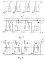
- FIGS 4, 5 and 6 show non-exhaustive examples of management of "all or nothing" energy sources.
- the connections are, in reality, realized by the intelligent element of each generator elementary according to the proper parameters of the generator itself or instructions provided by the outside environment to each smart element.
- the method according to the invention therefore makes it possible to identify, at all moment, each elementary generator and assign its use, series or parallel, to one point or another, without this attribution is final.
- the method according to the invention also makes it possible to manage certain well-known faults.
- Equipping elementary generators with intelligence allows you to control where, when, and how each generator distributes energy, in a structure designed for this purpose.
- Figure 7 shows schematically the architecture of a management system three elementary generators and the distribution, at all times, of current available to a source of use depending on a pilot which manages the information coming from these generators and takes into account any external elements.
- All or part of the matrix can be assigned, so scalable, at all or part of the points of energy use.
- the microsystem has a microsource of energy exactly suited to its needs and its lifespan.
- the "chip” does not just manage the microsource of energy, but integrates all the functionalities microsystem electronics.
- This same product in the context of another application where the standby current is zero, has an identical battery element but whose surface is reduced to the minimum achievable, taking into account that the amount of energy to be loaded is 375 times more small (the useful surface of the energy source is less than 2 mm2 - its size then only depends on its ability to provide the necessary energy peak!).
- the energy source is, then, the same size as that of electronics.
- the invention would not be departed from if the microsytem were equipped with a rechargeable, or remotely rechargeable, microsource of energy to allow the initial energy reserve to be reconstituted.
Landscapes
- Chemical & Material Sciences (AREA)
- Chemical Kinetics & Catalysis (AREA)
- Electrochemistry (AREA)
- General Chemical & Material Sciences (AREA)
- Engineering & Computer Science (AREA)
- Manufacturing & Machinery (AREA)
- Microelectronics & Electronic Packaging (AREA)
- Secondary Cells (AREA)
- Seeds, Soups, And Other Foods (AREA)
- Primary Cells (AREA)
- Battery Mounting, Suspending (AREA)
- Saccharide Compounds (AREA)
Description
Leur tension varie fortement au cours de leur durée de vie, et on leur reproche, tout à la fois, leur capacité limitée, leur encombrement, leur poids, et leur coût d'utilisation.
On peut corriger la plupart de ces faiblesses à l'aide de montages judicieusement choisis, extérieurs à la pile ou à l'accumulateur (voir, à titre d'exemple, les brevets WO 94/00888, 0 457 569, ou 2 672 713).
- de la quantité d'énergie disponible, à tout instant, dans un accumulateur,
- de la quantité d'énergie nécessaire pour le recharger,
- du contrôle et de l'estimation de la durée de vie totale de cet accumulateur, en fonction des conditions d'utilisation (nombre de cycles de charge et de décharge, température d'utilisation, appels de courant importants, fréquence des appels de courant...).
- de réaliser des piles intelligentes,
- de gérer des matrices de sources d'énergie,
- de créer une meilleure adéquation entre les moyens électroniques mis en oeuvre et la taille de la source d'énergie qui lui est associée dans le cadre de microsystèmes de très faible consommation.
- le terme "pile" pour désigner une batterie d'éléments primaires donc, non rechargeables,
- le terme "accumulateur" pour désigner une batterie d'éléments secondaires, donc rechargeables,
- le terme "générateur élémentaire" pour désigner un élément (ou couple électrochimique) d'accumulateur ou de pile, pouvant, en conséquence, être rechargeable ou non.
- contrôler la tension de sortie du générateur élémentaire,
- contrôler le courant traversant le générateur élémentaire,
- surveiller un ou plusieurs paramètres (température, PH, ...),
- calculer les énergies entrées ou sorties,
- mémoriser les résultats,
- transmettre des données vers un système centralisé de gestion,
- ou bien, simplement, réaliser une microsource d'énergie, rechargeable ou non.
caractérisé en ce que ce circuit électronique (20) est assemblé à l'intérieur même de la structure (10) du couple électrochimique formant le générateur élémentaire de pile ou d'accumulateur et est situé, de préférence, sur le collecteur de courant de l'anode (11), ou sur le collecteur de courant de la cathode (13) de ce couple électrochimique (Fig.3).
- les figures 1 et 2 schématisent le montage série (Fig.1) et parallèle (Fig.2) de trois générateurs élémentaires (10),
- la figure 3 représente l'assemblage d'un composant électronique (20) dans la structure d'un générateur élémentaire (10) où (11) et (13) sont l'anode ou la cathode (ou inversement) de ce générateur, (12) est l'électrolyte liquide ou solide, avec son séparateur (non représenté), (20) est une "puce" directement soudée sur (13), et (30) est la protection mécanique, électrique et étanche de la "puce" de préference par moulage transfert d'une résine époxy "faibles contraintes".
- la figure 4 représente un montage en série de quatre éléments où l'on constate que les générateurs élémentaires (101) et (103) sont effectivement connectés en série, tandis que les générateurs élémentaires (102) et (104) sont en attente soit comme réserve d'énergie soit pour cause de dysfonctionnement.
- la figure 5 représente un montage en parallèle de quatre éléments où l'on constate que les générateurs élémentaires (101) et (104) sont connectés en parallèle entre les lignes (0) et (II), tandis que le générateur élémentaire (102) est connecté en parallèle entre les lignes (0) et (I) et que le générateur élémentaire (103) est en attente soit comme réserve d'énergie soit pour cause de dysfonctionnement.
- la figure 6 représente un montage mixte de quatre éléments où l'on constate que les générateurs élémentaires (101) et (102) sont connectés en série entre les points (I') et (I") de la ligne (I), tandis que le générateur élémentaire (104) est connecté en parallèle entre les lignes (0) et (II) et que le générateur élémentaire (103) est en attente soit comme réserve d'énergie soit pour cause de dysfonctionnement,
- la figure 7 représente une batterie de trois générateurs élémentaires (10), chacun équipé d'un composant intelligent (20) dans une structure de gestion automatique de la source d'énergie,
- la figure 8 représente une matrice de vingt quatre générateurs élémentaires intelligents (10), dans une structure de répartition automatique, de la totalité, ou d'une partie des sources d'énergie, vers un ou plusieurs points d'utilisation,
- les figures 9/1 à 9/8 représentent différentes phases d'un mode préferentiel d'assemblage d'un ou plusieurs composants électroniques, sous forme de "puce", directement sur le collecteur de courant de l'anode ou de la cathode du générateur élémentaire, l'annexe "Procédé de Fabrication", page 12, explique les phases du mode preferentiel d'assemblage décrit en figure 9,
- enfin, les figures 10/a à 10/c représentent la vue de dessous, la vue en coupe, la vue de dessus et les connexions électriques entre la puce et le couple électrochimique d'un autre mode d'assemblage.
- (20) représente le composant,
- (30) représente la protection mécanique, électrique et étanche du composant,
- (40) représente schématiquement le renvoi électrique de l'élément (11) vers la face inférieure du substrat,
- (11),(12) et (13) représentent l'anode, l'électrolyte et son séparateur et la cathode du générateur élémentaire.
- (50) représente le boítier extérieur du générateur.
- Les connexions électriques externes, connues en soi ne sont pas représentées.
- La fig. 10/a représente la face inférieure du collecteur de courant de la cathode (ou de l'anode) sur laquelle on distingue quatre plots métallisés (131) servant à la connexion de la puce et un trou métallisé non débouchant (132), servant au renvoi du contact de cathode (ou d'anode) de part et d'autre du support de collecteur,
- La fig. 10/b représente, en coupe, les principes de connexion
(131) de la puce (20), de trou métallisé (132), d'encapsulage par
résine transfert (30).
On remarque, sur cette figure, que, contrairement à la figure 9, le moulage transfert a été fait, de façon connue en soi, de part et d'autre du support de collecteur afin d'assurer une meilleure tenue mécanique et une meilleure étanchéité. - La fig.10/c représente la face supérieure du collecteur de courant où l'on distingue une zone circulaire dégagée, non conductrice (133) sur laquelle vient s'accrocher la résine transfert de protection de la puce (30) et une zone dessinée, conductrice (134) constituant le collecteur de courant, proprement dit, sur lequel on vient déposer les matériaux actifs de la cathode (ou de l'anode).
- de surveiller les paramètres essentiels de fonctionnement de chacun des générateurs,
- d'intervenir séparément sur la fourniture d'énergie de chacun de ces générateurs et donc, de gérer globalement la source d'énergie.
- Sur tous les véhicules ayant une "batterie", on contrôle le courant de charge global de l'accumulateur ce qui préjuge d'un bon fonctionnement global de cette "batterie" mais ne permet pas de prévoir une panne prochaine suite à la défaillance d'un seul des générateurs élémentaires, ni même de connaítre la quantité d'énergie effectivement disponible dans la "batterie". Le contrôle, élément par élément, permet de gérer ce type de situation.
- De la même façon, un accumulateur pourra être équipé d'un avertisseur de décharge qui se déclenchera non plus sur une valeur de tension globale mais sur le fait qu'un des éléments a atteint le seuil de décharge à ne pas dépasser, même si le bon fonctionnements des autres éléments camoufle ce dysfonctionnement local.
- Dans le cas d'une utilisation dans les pays nordiques (basses
températures), les accumulateurs peuvent être équipés d'un système
de préchauffage auto-alimenté qui sera déclenché par l'un, au moins,
des éléments intelligents interdisant la fourniture d'énergie au
démarreur jusqu'à ce que tous les éléments de l'accumulateur et
l'électrolyte aient atteint la bonne température pour fournir le
maximum d'énergie électrique.
Un signal de préchauffage des éléments, semblable ou couplé au voyant de préchauffage bougie des moteurs diesel, peut être envoyé directement, du générateur, sur le tableau de bord du véhicule. - De même, un chargeur pourra contrôler l'état de charge exact d'un accumulateur grâce à la détection simultanée, par élément, de la dérivée de la courbe dé tension, de la dérivée de la courbe de température et de la différentielle entre l'énergie fournie et l'énergie restituée au niveau de chaque élément ...
- l'électronique est de faible encombrement, de faible consommation et de faible coût,
- les sources d'énergie sont souvent surdimensionnées en termes
de:
- trop d'énergie embarquée,
- trop de volume,
- trop de poids,
- prix excessif comparé au prix d'une "puce".
- élément de pile semi-rigide (au Lithium, par exemple)
- tension d'alimentation: 3V
- courant de veille: 1 microampère
- courant de fonctionnement: 20 milliampères
- durée de fonctionnement: 10 secondes
- période de vigilance (durée de vie du produit): 3 ans
- coût du produit, avec source d'énergie: quelques FF
- épaisseur maxi: 500 microns
- surface active: 3x2cm = 6cm 2
- quantité d'énergie embarquée: 27 millampères/Heure
La source d'énergie est, alors, de la même taille que celle de l'électronique.
Par contre, on ne sortirait pas de l'invention si le microsytème était équipé d'une microsource d'énergie rechargeable, ou télérechargeable, pour permettre de reconstituer la réserve d'énergie initiale.

Claims (10)
- Procédé d'interconnexion d'un générateur élémentaire de pile ou d'accumulateur avec un circuit électronique intelligent (20), composé d'un, ou plusieurs, composants électroniques, actifs ou passifs, sous forme de "puces", alimenté en énergie par le générateur élémentaire de pile ou d'accumulateur, caractérisé en ce que ce circuit électronique (20) est assemblé à l'intérieur même de la structure (10) du couple électrochimique formant le générateur élémentaire de pile ou d'accumulateur et est situé, sur le collecteur de courant de l'anode (11), ou sur le collecteur de courant de la cathode (13) de ce couple électrochimique.
- Procédé selon la revendication précédente, caractérisé en ce que la connexion d'anode ou de cathode (132), de l'élément de pile ou d'accumulateur est aussi utilisée pour transporter le signal de contrôle qui se trouve, alors, superposé au signal de fourniture d'énergie.
- Procédé selon l'une quelconque des revendications précédentes caractérisé en ce qu'il s'applique à tout type de pile ou d'accumulateur et à tout type de couple électrochimique rechargeable ou non.
- Procédé selon l'une quelconque des revendications précédentes caractérisé en ce que le circuit électronique (20) est assemblé sur la zone conductrice (134), du couple électrochimique (10), constituant le collecteur de courant, proprement dit, de l'anode (11), ou de la cathode (13), sur lequel on vient déposer les matériaux actifs de la cathode ou de l'anode.
- Procédé selon l'une quelconque des revendications 1) à 4) caractérisé en ce qu'il est utilisé pour réaliser une pluralité de couples électrochimiques intelligents et constituer, ainsi, une batterie de piles ou d'accumulateurs, intelligente, pouvant intégrer une électronique de gestion de la pluralité des couples électrochimiques intelligents.
- Procédé selon l'une quelconque des revendications 1) à 4) caractérisé en ce qu'il est utilisé pour réaliser une matrice de générateurs élémentaires, de piles ou d'accumulateurs, de technologies identiques ou différentes, permettant de gérer, dans un contexte global, les paramètres et conditions d'utilisation de chaque générateur, ou groupe de générateurs élémentaires.
- Procédé selon l'une quelconque des revendications précédentes, caractérisé en ce que les connexions d'anode ou de cathode, de la batterie de piles ou d'accumulateurs, sont aussi utilisées pour transporter les signaux de contrôle qui se trouvent, alors, superposés au signal de fourniture d'énergie.
- Procédé selon l'une des revendications 1) et 3), caractérisé en ce qu'il est utilisé pour réaliser une microsource d'énergie, rechargeable ou non, indissociable et exactement adaptée au microsytème pour lequel cette microsource est conçue.
- Procédé selon l'une quelconque des revendications précédentes, caractérisé en ce que les éléments intelligents insérés dans l'accumulateur comptabilisent la quantité d'énergie que celui-ci a fournie, ou qui lui a été restituée, afin de déterminer, à tout moment, la capacité réelle de l'accumulateur.
- Procédé selon l'une quelconque des revendications précédentes, caractérisé en ce que les éléments intelligents insérés dans la pile comptabilisent la quantité d'énergie que celle-ci a fournie afin de déterminer, à tout moment, sa capacité résiduelle.
Applications Claiming Priority (3)
| Application Number | Priority Date | Filing Date | Title |
|---|---|---|---|
| FR9605881 | 1996-05-07 | ||
| FR9605881A FR2748605B1 (fr) | 1996-05-07 | 1996-05-07 | Procede de fabrication d'un generateur elementaire de pile ou d'accumulateur intelligent |
| PCT/FR1997/000818 WO1997042677A1 (fr) | 1996-05-07 | 1997-05-07 | Procede de fabrication d'un generateur elementaire de pile ou d'accumulateur intelligent |
Publications (2)
| Publication Number | Publication Date |
|---|---|
| EP0958634A1 EP0958634A1 (fr) | 1999-11-24 |
| EP0958634B1 true EP0958634B1 (fr) | 2002-02-06 |
Family
ID=9492044
Family Applications (1)
| Application Number | Title | Priority Date | Filing Date |
|---|---|---|---|
| EP97924061A Expired - Lifetime EP0958634B1 (fr) | 1996-05-07 | 1997-05-07 | Procede de fabrication d'un generateur elementaire de pile ou d'accumulateur intelligent |
Country Status (11)
| Country | Link |
|---|---|
| US (1) | US6593669B1 (fr) |
| EP (1) | EP0958634B1 (fr) |
| JP (1) | JP2000509881A (fr) |
| AT (1) | ATE213099T1 (fr) |
| CA (1) | CA2254088C (fr) |
| DE (1) | DE69710369T2 (fr) |
| DK (1) | DK0958634T3 (fr) |
| ES (1) | ES2171941T3 (fr) |
| FR (1) | FR2748605B1 (fr) |
| PT (1) | PT958634E (fr) |
| WO (1) | WO1997042677A1 (fr) |
Cited By (1)
| Publication number | Priority date | Publication date | Assignee | Title |
|---|---|---|---|---|
| US7193392B2 (en) | 2002-11-25 | 2007-03-20 | Tiax Llc | System and method for determining and balancing state of charge among series connected electrical energy storage units |
Families Citing this family (22)
| Publication number | Priority date | Publication date | Assignee | Title |
|---|---|---|---|---|
| FR2912261B1 (fr) * | 2007-02-07 | 2009-07-17 | Peugeot Citroen Automobiles Sa | Dispositif de fourniture d'energie electrique |
| DE102008010971A1 (de) * | 2008-02-25 | 2009-08-27 | Robert Bosch Gmbh | Schutzsystem für Batteriemodule |
| DE102009000674A1 (de) * | 2009-02-06 | 2010-08-12 | Robert Bosch Gmbh | Traktionsbatterie mit erhöhter Verfügbarkeit |
| DE102009000676A1 (de) * | 2009-02-06 | 2010-08-12 | Robert Bosch Gmbh | Traktionsbatterie mit erhöhter Zuverlässigkeit |
| US8889312B2 (en) | 2009-07-29 | 2014-11-18 | The Invention Science Fund I, Llc | Instrumented fluid-surfaced electrode |
| US8460814B2 (en) * | 2009-07-29 | 2013-06-11 | The Invention Science Fund I, Llc | Fluid-surfaced electrode |
| US20110027638A1 (en) * | 2009-07-29 | 2011-02-03 | Searete Llc, A Limited Liability Corporation Of The State Of Delaware | Fluid-surfaced electrode |
| US20110027637A1 (en) * | 2009-07-29 | 2011-02-03 | Searete Llc, A Limited Liability Corporation Of The State Of Delaware | Fluid-surfaced electrode |
| US10074879B2 (en) | 2009-07-29 | 2018-09-11 | Deep Science, Llc | Instrumented fluid-surfaced electrode |
| US8865361B2 (en) * | 2009-07-29 | 2014-10-21 | The Invention Science Fund I, Llc | Instrumented fluid-surfaced electrode |
| EP2328173B1 (fr) | 2009-11-26 | 2016-03-30 | Nxp B.V. | Batterie intégrée et circuit intégré |
| DE102012205937A1 (de) * | 2012-04-12 | 2013-10-17 | Robert Bosch Gmbh | Sensorvorrichtung für einen elektrochemischen Energiespeicher, elektrochemischer Energiespeicher, Verfahren zum Herstellen einer Sensorvorrichtung für einen elektrochemischen Energiespeicher und Verfahren zum elektrischen Kontaktieren einer Sensorvorrichtung in einem elektrochemischen Energiespeicher |
| DE102012209709B4 (de) * | 2012-06-11 | 2021-10-07 | Robert Bosch Gmbh | Schutzvorrichtung für ein elektronisches Bauelement, elektrische Schaltung, elektrochemischer Energiespeicher, Verfahren zum Herstellen einer elektrischen Schaltung und Verwendung einer flexiblen Hülle |
| US9484601B2 (en) | 2013-07-30 | 2016-11-01 | Elwha Llc | Load-managed electrochemical energy generation system |
| US9893369B2 (en) | 2013-07-30 | 2018-02-13 | Elwha Llc | Managed access electrochemical energy generation system |
| US9343783B2 (en) | 2013-07-30 | 2016-05-17 | Elwha Llc | Electrochemical energy generation system having individually controllable cells |
| EP2950381B1 (fr) * | 2014-05-28 | 2016-12-14 | EM Microelectronic-Marin SA | Batterie intelligente avec un circuit de gestion de la tension d'alimentation, et procédé de fabrication de la batterie |
| DE102018221836A1 (de) * | 2018-12-14 | 2020-06-18 | Robert Bosch Gmbh | Energiespeicher für ein elektrisch antreibbares Fortbewegungsmittel |
| DE102019203810A1 (de) * | 2019-03-20 | 2020-09-24 | Robert Bosch Gmbh | Batteriesystem für ein Kraftfahrzeug |
| DE102019212677A1 (de) * | 2019-08-23 | 2021-02-25 | Airbus Operations Gmbh | Anzeigevorrichtung und Verfahren zu deren Herstellung |
| DE102019215805A1 (de) * | 2019-10-15 | 2021-01-07 | Vitesco Technologies GmbH | Anordnung zur Zustandsbestimmung bei einer Batteriezelle, Batteriemanagementvorrichtung und Batteriesystem mit einer Anordnung |
| FR3153696A1 (fr) * | 2023-10-03 | 2025-04-04 | Pellenc Energy | Procédé d’association d’un microcircuit à une cellule de batterie |
Family Cites Families (21)
| Publication number | Priority date | Publication date | Assignee | Title |
|---|---|---|---|---|
| US3793078A (en) * | 1972-05-04 | 1974-02-19 | Hughes Aircraft Co | Negative electrode with an insulated body of conductor material supported therein |
| US4062750A (en) * | 1974-12-18 | 1977-12-13 | James Francis Butler | Thin film electrochemical electrode and cell |
| DE3207131A1 (de) * | 1982-02-27 | 1983-09-08 | Rosenthal Technik Ag, 8672 Selb | Keramiksubstrat als traeger fuer elektronische bauelemente und integrierte elektronische schaltkreise |
| JPS6012679A (ja) * | 1983-07-01 | 1985-01-23 | Matsushita Electric Ind Co Ltd | 情報記憶素子 |
| US4874500A (en) * | 1987-07-15 | 1989-10-17 | Sri International | Microelectrochemical sensor and sensor array |
| JP2758030B2 (ja) * | 1988-07-04 | 1998-05-25 | ソニー株式会社 | 薄型電子機器とその製造方法 |
| JPH0799384B2 (ja) * | 1988-09-13 | 1995-10-25 | 日本電気株式会社 | 電池残量表示装置 |
| FR2654553A1 (fr) * | 1989-11-14 | 1991-05-17 | Atlantique Technologies | Procede de gestion pour l'exploitation de batteries d'accumulateurs fixes ou embarquees et dispositif integre pour sa mise en óoeuvre. |
| US5147985A (en) * | 1990-08-14 | 1992-09-15 | The Scabbard Corporation | Sheet batteries as substrate for electronic circuit |
| EP0644642A3 (fr) * | 1993-07-30 | 1995-05-24 | Texas Instruments Inc | Alimentation électrique. |
| US5622789A (en) | 1994-09-12 | 1997-04-22 | Apple Computer, Inc. | Battery cell having an internal circuit for controlling its operation |
| US5593794A (en) * | 1995-01-23 | 1997-01-14 | Duracell Inc. | Moisture barrier composite film of silicon nitride and fluorocarbon polymer and its use with an on-cell tester for an electrochemical cell |
| US5563002A (en) | 1995-02-21 | 1996-10-08 | Motorola, Inc. | Programmable battery |
| US5897522A (en) * | 1995-12-20 | 1999-04-27 | Power Paper Ltd. | Flexible thin layer open electrochemical cell and applications of same |
| US5637418A (en) * | 1996-02-08 | 1997-06-10 | Motorola, Inc. | Package for a flat electrochemical device |
| AUPO581397A0 (en) * | 1997-03-21 | 1997-04-17 | Memtec America Corporation | Sensor connection means |
| US6156450A (en) * | 1997-07-24 | 2000-12-05 | Eveready Battery Company, Inc. | Battery tester having printed electronic components |
| US5990659A (en) | 1997-10-01 | 1999-11-23 | Telefonaktiebolaget Lm Ericsson | Battery pack that communicates intrinsic information over battery voltage terminals |
| US6074775A (en) * | 1998-04-02 | 2000-06-13 | The Procter & Gamble Company | Battery having a built-in controller |
| US6217744B1 (en) * | 1998-12-18 | 2001-04-17 | Peter Crosby | Devices for testing fluid |
| WO2000062365A1 (fr) * | 1999-04-14 | 2000-10-19 | Power Paper Ltd. | Pile a fonctions ameliorees et son procede de fabrication |
-
1996
- 1996-05-07 FR FR9605881A patent/FR2748605B1/fr not_active Expired - Fee Related
-
1997
- 1997-05-07 WO PCT/FR1997/000818 patent/WO1997042677A1/fr not_active Ceased
- 1997-05-07 EP EP97924061A patent/EP0958634B1/fr not_active Expired - Lifetime
- 1997-05-07 PT PT97924061T patent/PT958634E/pt unknown
- 1997-05-07 CA CA 2254088 patent/CA2254088C/fr not_active Expired - Fee Related
- 1997-05-07 DE DE69710369T patent/DE69710369T2/de not_active Expired - Fee Related
- 1997-05-07 AT AT97924061T patent/ATE213099T1/de not_active IP Right Cessation
- 1997-05-07 JP JP53960697A patent/JP2000509881A/ja active Pending
- 1997-05-07 ES ES97924061T patent/ES2171941T3/es not_active Expired - Lifetime
- 1997-05-07 DK DK97924061T patent/DK0958634T3/da active
-
2000
- 2000-07-20 US US09/620,574 patent/US6593669B1/en not_active Expired - Fee Related
Cited By (3)
| Publication number | Priority date | Publication date | Assignee | Title |
|---|---|---|---|---|
| US7193392B2 (en) | 2002-11-25 | 2007-03-20 | Tiax Llc | System and method for determining and balancing state of charge among series connected electrical energy storage units |
| US7245108B2 (en) | 2002-11-25 | 2007-07-17 | Tiax Llc | System and method for balancing state of charge among series-connected electrical energy storage units |
| US7378818B2 (en) | 2002-11-25 | 2008-05-27 | Tiax Llc | Bidirectional power converter for balancing state of charge among series connected electrical energy storage units |
Also Published As
| Publication number | Publication date |
|---|---|
| US6593669B1 (en) | 2003-07-15 |
| FR2748605A1 (fr) | 1997-11-14 |
| DE69710369T2 (de) | 2002-11-07 |
| ATE213099T1 (de) | 2002-02-15 |
| CA2254088A1 (fr) | 1997-11-13 |
| EP0958634A1 (fr) | 1999-11-24 |
| DK0958634T3 (da) | 2002-05-27 |
| JP2000509881A (ja) | 2000-08-02 |
| DE69710369D1 (de) | 2002-03-21 |
| WO1997042677A1 (fr) | 1997-11-13 |
| PT958634E (pt) | 2002-07-31 |
| CA2254088C (fr) | 2006-01-17 |
| FR2748605B1 (fr) | 1998-08-07 |
| ES2171941T3 (es) | 2002-09-16 |
Similar Documents
| Publication | Publication Date | Title |
|---|---|---|
| EP0958634B1 (fr) | Procede de fabrication d'un generateur elementaire de pile ou d'accumulateur intelligent | |
| EP0533577B1 (fr) | Collecteurs de courant pour générateurs électrochimiques sécuritaires, procédés de préparation et générateurs obtenus | |
| EP2609643B1 (fr) | Accumulateur electrochimique bipolaire a emballage ameliore | |
| EP3076453B1 (fr) | Dispositif électrochimique, tel qu'une microbatterie ou un système électrochrome, recouvert par une couche d'encapsulation comprenant un film barrière et un film adhésif, et procédé de réalisation d'un tel dispositif | |
| EP2416468A2 (fr) | Procédé d'équilibrage pour batterie électrique et système de gestion pour batterie mettant en ouvre un tel procédé | |
| FR3006812A1 (fr) | Gestion de la duree de vie d'une batterie | |
| EP0310075A2 (fr) | Générateur électrochimique amorçable mettant en oeuvre des couples lithium/oxyhalogénure | |
| FR2946459A1 (fr) | Element de structure pour panneau solaire, et structure comportant un tel element | |
| FR2916579A1 (fr) | Boitier electronique pour batterie. | |
| WO2013076260A1 (fr) | Procede de fabrication d'une batterie tout solide | |
| EP0114667B1 (fr) | Générateur électrochimique de type bouton | |
| EP2101336A1 (fr) | Dispositif accumulateur d'energie electrique et train comportant une pluralite de tels dispositifs | |
| JPH10341032A (ja) | 太陽電池モジュールの製造方法 | |
| FR2692077A1 (fr) | Accumulateurs à électrodes bipolaires. | |
| FR2748608A1 (fr) | Systeme electronique pour batterie bipolaire et carte pour ce systeme | |
| FR3153693A1 (fr) | Dispositif de stockage d’energie electrique presentant une architecture perfectionnee, procede de fabrication et ensemble de consommation d’energie correspondants | |
| FR3105602A1 (fr) | Dispositif électrochimique de type batterie, comprenant des moyens d’étanchéité perfectionnés, et son procédé de fabrication | |
| FR2986382A1 (fr) | Circuit electronique de recuperation, de stockage et de restitution d'energie electrique et le procede associe | |
| FR3058267A1 (fr) | Procede d'equilibrage des etats de vieillissement (soh et/ou sop) d'un pack-batterie comprenant une pluralite d'accumulateurs electrochimiques metal-ion | |
| FR2608323A1 (fr) | Dispositif de surveillance de la charge d'une batterie | |
| FR3016241A1 (fr) | Ensemble de stockage d'energie electrique, et procede de fabrication associe | |
| FR3011985A1 (fr) | Accumulateur d'energie lithium-ion et procede de saisie de son niveau de charge | |
| FR3128059A1 (fr) | Batterie à électrolyte solide | |
| FR2912261A1 (fr) | Dispositif de fourniture d'energie electrique | |
| FR3153696A1 (fr) | Procédé d’association d’un microcircuit à une cellule de batterie |
Legal Events
| Date | Code | Title | Description |
|---|---|---|---|
| PUAI | Public reference made under article 153(3) epc to a published international application that has entered the european phase |
Free format text: ORIGINAL CODE: 0009012 |
|
| 17P | Request for examination filed |
Effective date: 19981109 |
|
| AK | Designated contracting states |
Kind code of ref document: A1 Designated state(s): AT BE CH DE DK ES FI FR GB GR IE IT LI LU MC NL PT SE |
|
| RAP1 | Party data changed (applicant data changed or rights of an application transferred) |
Owner name: TECHNOPUCE INTERNATIONAL |
|
| GRAG | Despatch of communication of intention to grant |
Free format text: ORIGINAL CODE: EPIDOS AGRA |
|
| 17Q | First examination report despatched |
Effective date: 20010703 |
|
| GRAG | Despatch of communication of intention to grant |
Free format text: ORIGINAL CODE: EPIDOS AGRA |
|
| GRAH | Despatch of communication of intention to grant a patent |
Free format text: ORIGINAL CODE: EPIDOS IGRA |
|
| GRAH | Despatch of communication of intention to grant a patent |
Free format text: ORIGINAL CODE: EPIDOS IGRA |
|
| GRAA | (expected) grant |
Free format text: ORIGINAL CODE: 0009210 |
|
| REG | Reference to a national code |
Ref country code: GB Ref legal event code: IF02 |
|
| RAP1 | Party data changed (applicant data changed or rights of an application transferred) |
Owner name: TECHNOPUCE INTERNATIONAL |
|
| AK | Designated contracting states |
Kind code of ref document: B1 Designated state(s): AT BE CH DE DK ES FI FR GB GR IE IT LI LU MC NL PT SE |
|
| REF | Corresponds to: |
Ref document number: 213099 Country of ref document: AT Date of ref document: 20020215 Kind code of ref document: T |
|
| REG | Reference to a national code |
Ref country code: CH Ref legal event code: EP |
|
| RAP2 | Party data changed (patent owner data changed or rights of a patent transferred) |
Owner name: TECHNOPUCE |
|
| REF | Corresponds to: |
Ref document number: 69710369 Country of ref document: DE Date of ref document: 20020321 |
|
| PGFP | Annual fee paid to national office [announced via postgrant information from national office to epo] |
Ref country code: GR Payment date: 20020426 Year of fee payment: 6 Ref country code: SE Payment date: 20020426 Year of fee payment: 6 |
|
| PGFP | Annual fee paid to national office [announced via postgrant information from national office to epo] |
Ref country code: FI Payment date: 20020508 Year of fee payment: 6 |
|
| PGFP | Annual fee paid to national office [announced via postgrant information from national office to epo] |
Ref country code: DK Payment date: 20020510 Year of fee payment: 6 |
|
| PGFP | Annual fee paid to national office [announced via postgrant information from national office to epo] |
Ref country code: IE Payment date: 20020514 Year of fee payment: 6 |
|
| PGFP | Annual fee paid to national office [announced via postgrant information from national office to epo] |
Ref country code: DE Payment date: 20020516 Year of fee payment: 6 |
|
| PGFP | Annual fee paid to national office [announced via postgrant information from national office to epo] |
Ref country code: BE Payment date: 20020517 Year of fee payment: 6 |
|
| GBT | Gb: translation of ep patent filed (gb section 77(6)(a)/1977) |
Effective date: 20020501 |
|
| PGFP | Annual fee paid to national office [announced via postgrant information from national office to epo] |
Ref country code: MC Payment date: 20020527 Year of fee payment: 6 |
|
| REG | Reference to a national code |
Ref country code: DK Ref legal event code: T3 |
|
| PGFP | Annual fee paid to national office [announced via postgrant information from national office to epo] |
Ref country code: AT Payment date: 20020529 Year of fee payment: 6 |
|
| PGFP | Annual fee paid to national office [announced via postgrant information from national office to epo] |
Ref country code: NL Payment date: 20020531 Year of fee payment: 6 Ref country code: ES Payment date: 20020531 Year of fee payment: 6 |
|
| REG | Reference to a national code |
Ref country code: CH Ref legal event code: NV Representative=s name: R. A. EGLI & CO. PATENTANWAELTE |
|
| NLT2 | Nl: modifications (of names), taken from the european patent patent bulletin |
Owner name: TECHNOPUCE |
|
| PGFP | Annual fee paid to national office [announced via postgrant information from national office to epo] |
Ref country code: LU Payment date: 20020607 Year of fee payment: 6 |
|
| REG | Reference to a national code |
Ref country code: PT Ref legal event code: SC4A Free format text: AVAILABILITY OF NATIONAL TRANSLATION Effective date: 20020408 |
|
| PGFP | Annual fee paid to national office [announced via postgrant information from national office to epo] |
Ref country code: CH Payment date: 20020828 Year of fee payment: 6 |
|
| REG | Reference to a national code |
Ref country code: GR Ref legal event code: EP Ref document number: 20020401466 Country of ref document: GR |
|
| REG | Reference to a national code |
Ref country code: ES Ref legal event code: FG2A Ref document number: 2171941 Country of ref document: ES Kind code of ref document: T3 |
|
| PLBE | No opposition filed within time limit |
Free format text: ORIGINAL CODE: 0009261 |
|
| STAA | Information on the status of an ep patent application or granted ep patent |
Free format text: STATUS: NO OPPOSITION FILED WITHIN TIME LIMIT |
|
| 26N | No opposition filed |
Effective date: 20021107 |
|
| PG25 | Lapsed in a contracting state [announced via postgrant information from national office to epo] |
Ref country code: LU Free format text: LAPSE BECAUSE OF NON-PAYMENT OF DUE FEES Effective date: 20030507 Ref country code: IE Free format text: LAPSE BECAUSE OF NON-PAYMENT OF DUE FEES Effective date: 20030507 Ref country code: FI Free format text: LAPSE BECAUSE OF NON-PAYMENT OF DUE FEES Effective date: 20030507 Ref country code: AT Free format text: LAPSE BECAUSE OF NON-PAYMENT OF DUE FEES Effective date: 20030507 |
|
| PG25 | Lapsed in a contracting state [announced via postgrant information from national office to epo] |
Ref country code: SE Free format text: LAPSE BECAUSE OF NON-PAYMENT OF DUE FEES Effective date: 20030508 Ref country code: ES Free format text: LAPSE BECAUSE OF NON-PAYMENT OF DUE FEES Effective date: 20030508 |
|
| PGFP | Annual fee paid to national office [announced via postgrant information from national office to epo] |
Ref country code: PT Payment date: 20030508 Year of fee payment: 7 |
|
| PG25 | Lapsed in a contracting state [announced via postgrant information from national office to epo] |
Ref country code: MC Free format text: LAPSE BECAUSE OF NON-PAYMENT OF DUE FEES Effective date: 20030531 Ref country code: LI Free format text: LAPSE BECAUSE OF NON-PAYMENT OF DUE FEES Effective date: 20030531 Ref country code: CH Free format text: LAPSE BECAUSE OF NON-PAYMENT OF DUE FEES Effective date: 20030531 Ref country code: BE Free format text: LAPSE BECAUSE OF NON-PAYMENT OF DUE FEES Effective date: 20030531 |
|
| NLT2 | Nl: modifications (of names), taken from the european patent patent bulletin |
Owner name: TECHNOPUCE |
|
| BERE | Be: lapsed |
Owner name: *TECHNOPUCE Effective date: 20030531 |
|
| PG25 | Lapsed in a contracting state [announced via postgrant information from national office to epo] |
Ref country code: NL Free format text: LAPSE BECAUSE OF NON-PAYMENT OF DUE FEES Effective date: 20031201 Ref country code: DK Free format text: LAPSE BECAUSE OF NON-PAYMENT OF DUE FEES Effective date: 20031201 |
|
| PG25 | Lapsed in a contracting state [announced via postgrant information from national office to epo] |
Ref country code: DE Free format text: LAPSE BECAUSE OF NON-PAYMENT OF DUE FEES Effective date: 20031202 |
|
| PG25 | Lapsed in a contracting state [announced via postgrant information from national office to epo] |
Ref country code: GR Free format text: LAPSE BECAUSE OF NON-PAYMENT OF DUE FEES Effective date: 20031203 |
|
| REG | Reference to a national code |
Ref country code: DK Ref legal event code: EBP |
|
| EUG | Se: european patent has lapsed | ||
| REG | Reference to a national code |
Ref country code: CH Ref legal event code: PL |
|
| NLV4 | Nl: lapsed or anulled due to non-payment of the annual fee |
Effective date: 20031201 |
|
| REG | Reference to a national code |
Ref country code: IE Ref legal event code: MM4A |
|
| REG | Reference to a national code |
Ref country code: ES Ref legal event code: FD2A Effective date: 20030508 |
|
| PG25 | Lapsed in a contracting state [announced via postgrant information from national office to epo] |
Ref country code: PT Free format text: LAPSE BECAUSE OF NON-PAYMENT OF DUE FEES Effective date: 20041108 |
|
| REG | Reference to a national code |
Ref country code: PT Ref legal event code: MM4A Effective date: 20041108 |
|
| PG25 | Lapsed in a contracting state [announced via postgrant information from national office to epo] |
Ref country code: IT Free format text: LAPSE BECAUSE OF NON-PAYMENT OF DUE FEES;WARNING: LAPSES OF ITALIAN PATENTS WITH EFFECTIVE DATE BEFORE 2007 MAY HAVE OCCURRED AT ANY TIME BEFORE 2007. THE CORRECT EFFECTIVE DATE MAY BE DIFFERENT FROM THE ONE RECORDED. Effective date: 20050507 |
|
| PGFP | Annual fee paid to national office [announced via postgrant information from national office to epo] |
Ref country code: GB Payment date: 20060517 Year of fee payment: 10 |
|
| GBPC | Gb: european patent ceased through non-payment of renewal fee |
Effective date: 20070507 |
|
| PGFP | Annual fee paid to national office [announced via postgrant information from national office to epo] |
Ref country code: FR Payment date: 20070531 Year of fee payment: 11 |
|
| PG25 | Lapsed in a contracting state [announced via postgrant information from national office to epo] |
Ref country code: GB Free format text: LAPSE BECAUSE OF NON-PAYMENT OF DUE FEES Effective date: 20070507 |
|
| REG | Reference to a national code |
Ref country code: FR Ref legal event code: ST Effective date: 20090119 |
|
| PG25 | Lapsed in a contracting state [announced via postgrant information from national office to epo] |
Ref country code: FR Free format text: LAPSE BECAUSE OF NON-PAYMENT OF DUE FEES Effective date: 20080602 |