EP0957603A2 - Integrated telecommunications line systems and cross-connect - Google Patents
Integrated telecommunications line systems and cross-connect Download PDFInfo
- Publication number
- EP0957603A2 EP0957603A2 EP99108770A EP99108770A EP0957603A2 EP 0957603 A2 EP0957603 A2 EP 0957603A2 EP 99108770 A EP99108770 A EP 99108770A EP 99108770 A EP99108770 A EP 99108770A EP 0957603 A2 EP0957603 A2 EP 0957603A2
- Authority
- EP
- European Patent Office
- Prior art keywords
- cross
- traffic
- point
- path
- connect
- Prior art date
- Legal status (The legal status is an assumption and is not a legal conclusion. Google has not performed a legal analysis and makes no representation as to the accuracy of the status listed.)
- Granted
Links
- 230000001360 synchronised effect Effects 0.000 claims abstract description 21
- 239000011159 matrix material Substances 0.000 claims description 21
- 238000000034 method Methods 0.000 claims description 15
- 238000012545 processing Methods 0.000 claims description 6
- 101150067286 STS1 gene Proteins 0.000 claims description 3
- 101100028967 Saccharomyces cerevisiae (strain ATCC 204508 / S288c) PDR5 gene Proteins 0.000 claims description 3
- 101150027289 Ubash3b gene Proteins 0.000 claims description 3
- 102100040338 Ubiquitin-associated and SH3 domain-containing protein B Human genes 0.000 claims description 3
- 230000005540 biological transmission Effects 0.000 abstract description 6
- 101150012532 NANOG gene Proteins 0.000 description 19
- 101100396520 Saccharomyces cerevisiae (strain ATCC 204508 / S288c) TIF3 gene Proteins 0.000 description 19
- 101150038107 stm1 gene Proteins 0.000 description 19
- 230000006870 function Effects 0.000 description 10
- RGNPBRKPHBKNKX-UHFFFAOYSA-N hexaflumuron Chemical compound C1=C(Cl)C(OC(F)(F)C(F)F)=C(Cl)C=C1NC(=O)NC(=O)C1=C(F)C=CC=C1F RGNPBRKPHBKNKX-UHFFFAOYSA-N 0.000 description 8
- 230000009977 dual effect Effects 0.000 description 4
- 230000000052 comparative effect Effects 0.000 description 3
- 238000010586 diagram Methods 0.000 description 3
- 230000000903 blocking effect Effects 0.000 description 2
- 238000004891 communication Methods 0.000 description 2
- 238000010276 construction Methods 0.000 description 2
- 238000009434 installation Methods 0.000 description 2
- 238000012423 maintenance Methods 0.000 description 2
- 230000003287 optical effect Effects 0.000 description 2
- 238000006243 chemical reaction Methods 0.000 description 1
- 230000008878 coupling Effects 0.000 description 1
- 238000010168 coupling process Methods 0.000 description 1
- 238000005859 coupling reaction Methods 0.000 description 1
- 230000000694 effects Effects 0.000 description 1
- 238000005516 engineering process Methods 0.000 description 1
- 230000015654 memory Effects 0.000 description 1
- 238000012986 modification Methods 0.000 description 1
- 230000004048 modification Effects 0.000 description 1
- 238000012544 monitoring process Methods 0.000 description 1
- 238000011084 recovery Methods 0.000 description 1
- 230000011664 signaling Effects 0.000 description 1
- 230000003936 working memory Effects 0.000 description 1
Images


Classifications
-
- H—ELECTRICITY
- H04—ELECTRIC COMMUNICATION TECHNIQUE
- H04J—MULTIPLEX COMMUNICATION
- H04J3/00—Time-division multiplex systems
- H04J3/16—Time-division multiplex systems in which the time allocation to individual channels within a transmission cycle is variable, e.g. to accommodate varying complexity of signals, to vary number of channels transmitted
- H04J3/1605—Fixed allocated frame structures
- H04J3/1611—Synchronous digital hierarchy [SDH] or SONET
-
- H—ELECTRICITY
- H04—ELECTRIC COMMUNICATION TECHNIQUE
- H04Q—SELECTING
- H04Q11/00—Selecting arrangements for multiplex systems
- H04Q11/04—Selecting arrangements for multiplex systems for time-division multiplexing
- H04Q11/0428—Integrated services digital network, i.e. systems for transmission of different types of digitised signals, e.g. speech, data, telecentral, television signals
- H04Q11/0478—Provisions for broadband connections
-
- H—ELECTRICITY
- H04—ELECTRIC COMMUNICATION TECHNIQUE
- H04J—MULTIPLEX COMMUNICATION
- H04J2203/00—Aspects of optical multiplex systems other than those covered by H04J14/05 and H04J14/07
- H04J2203/0001—Provisions for broadband connections in integrated services digital network using frames of the Optical Transport Network [OTN] or using synchronous transfer mode [STM], e.g. SONET, SDH
- H04J2203/0051—Network Node Interface, e.g. tandem connections, transit switching
- H04J2203/0053—Routing
-
- H—ELECTRICITY
- H04—ELECTRIC COMMUNICATION TECHNIQUE
- H04J—MULTIPLEX COMMUNICATION
- H04J2203/00—Aspects of optical multiplex systems other than those covered by H04J14/05 and H04J14/07
- H04J2203/0001—Provisions for broadband connections in integrated services digital network using frames of the Optical Transport Network [OTN] or using synchronous transfer mode [STM], e.g. SONET, SDH
- H04J2203/0064—Admission Control
- H04J2203/0067—Resource management and allocation
- H04J2203/0069—Channel allocation
Definitions
- synchronous (SDH or SONET) transport networks incorporate backbones that been designed using cross-connects as flexibility points linked by line systems.
- SDH synchronous
- SONET transport-layer-layer-layer-layer-layer-layer-layer-layer-layer-layer-layer-layer-layer-layer-layer-layer-layer-layer-layer-layer-layer-layer-layer-layer-layer-layer-layer-layer-layer-layer-layer-layer-layer-layer-layers.
- VC4 management the primary function of the cross-connects in the backbone
- 3x3 cross-connects serve a similar function to provide management at the sts-1 level.
- line systems comprise either;
- a synchronous network digital traffic is transported as the payload in virtual containers to which overheads are attached and which are then incorporated in frames.
- the international synchronous network standards define different combinations of virtual containers that can be used to fill the payload area of a frame. The process of loading containers and attaching overheads is repeated at a number of multiplexing levels
- an integrated line system/cross-connect arrangement for switching traffic carried on first and second paths in a synchronous telecommunications network, the arrangement including means for determining for each said path the traffic that is to remain on that path through the cross-point and the traffic that is to be switched from that path at the cross-point, means dropping only the traffic to be switched at the cross-point, and means for switching the dropped traffic.
Abstract
Description
- This invention relates to telecommunications systems and in particular to the provision and operation of cross-connects in synchronous transport networks.
- Traditionally, synchronous (SDH or SONET) transport networks incorporate backbones that been designed using cross-connects as flexibility points linked by line systems. In European SDH networks, the primary function of the cross-connects in the backbone is VC4 management for routing and restoration. In North American SONET networks, 3x3 cross-connects serve a similar function to provide management at the sts-1 level.
- In these networks, line systems comprise either;
- unprotected 1+1 or 1:N protected line systems interconnecting cross-connects in a mesh arrangement; or
- ring systems with either unidirectional (DPRing) or bi-directional (MS-SPRing) rings.
-
- In Europe, the most common network strategy has been the use of the mesh arrangement with unprotected STM16 (2.5 Gbit/s) line systems. In North America, long distance transport employs meshing with 1:N OC48 (2.5 Gbit/s) line systems, while regional operating companies employ ring systems.
- In a synchronous network, digital traffic is transported as the payload in virtual containers to which overheads are attached and which are then incorporated in frames. The international synchronous network standards define different combinations of virtual containers that can be used to fill the payload area of a frame. The process of loading containers and attaching overheads is repeated at a number of multiplexing levels
- A description of a SONET cross connect is given by F G Noser in specification No. EP-A2-0 559 091. A description of a cross connect architecture for SDH signals is given by R Ahola et al. in specification No WO 95/32599.
- With the constantly increasing traffic demand, operators are now installing higher capacity transport systems, the new standard being 10 Gbit/s which corresponds to the SDH STM64 standard or the SONET OC192 standard. The large increase in network bandwidth that is provided by these high capacity transport systems has introduced a consequent need for growth in the size of cross-connects, particularly in meshed networks. At a cross-connect, the incoming signal is demultiplexed into its components which are individually switched before being re-multiplexed for onward transmission. However, the cross-connect sizes that are now being demanded for these high capacity systems exceed the capabilities of the equipment suppliers. Using current technology, a cross-connect of the required capacity would require numerous interface shelves and a large amount of cross-site cabling between the line systems and the cross-connect. This lack of availability of a suitable cross-connect at an acceptable cost has placed constraints on the introduction of higher bit rate systems.
- An object of the invention is to minimise or to overcome this disadvantage.
- A further object of the invention is to provide an improved cross-connect for a synchronous transport network.
- A further object of the invention is to provide an improved method of handling traffic at a cross-connect in a synchronous network.
- According to the invention there is provided an integrated line system/cross-connect arrangement for switching traffic carried on first and second paths in a synchronous telecommunications network, the arrangement including means for determining for each said path the traffic that is to remain on that path through the cross-point and the traffic that is to be switched from that path at the cross-point, means dropping only the traffic to be switched at the cross-point, and means for switching the dropped traffic.
- According to another aspect of the invention, there is provided a method of switching traffic carried on first and second paths at a cross-point in a synchronous network, the method including determining for each said path the traffic that is to remain on that path through the cross-point and the traffic that is to be switched from that path at the cross-point, dropping only the traffic to be switched at the cross-point, and switching the dropped traffic.
- According to a further aspect of the invention there is provided a method of processing traffic carried on first and second paths at a cross-point in a synchronous network, the method including transporting the traffic on each path in virtual containers, each of which virtual containers contains either traffic that is to remain on that path at the cross-point or traffic that is to be switched to the other path at the cross-point, and switching at the cross point those virtual containers containing the traffic to be switched.
- In this system and method, traffic is loaded into appropriate virtual containers according the route that it will take at a cross-point, i.e. to be switched from one path to another or to continue on the same path. Switching at the cross-connect is performed at the virtual container (VC4 or STS1) level.
- According to a further aspect of the invention there is provided a synchronous network incorporating an integrated line system/cross-connect arrangement for processing traffic carried on first and second paths at a cross-point in the network, the network having means for transporting the traffic on each path, each of which virtual containers contains either traffic that is to remain on that path at the cross-point or traffic that is to be switched to the other path at the cross-point, and wherein the cross point has means for switching those virtual containers containing the traffic to be switched.
- By dropping out only the traffic that needs to be switched at the cross-point, the demand on the switching equipment is significantly reduced.
- A preferred embodiment of the invention will now be described with reference to the accompanying drawings in which;
- Figure 1 is a schematic diagram of a synchronous transport network;
- Figure 2 shows for comparative purposes the general configuration of a conventional cross-connect arrangement.
- Figure 3 is a schematic diagram of an integrated line system/cross-connect according to a preferred exemplary embodiment of the invention;
- Figure 4 shows the integrated line system/cross-connect of figure 3 in further detail;
- Figure 5 illustrates the equipment configuration of the cross-connect of figures 3 and 4; and
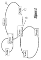
- Figure 6 is a schematic diagram illustrating traffic paths through a node incorporating the cross connect of figures 3 and 4.
-
- Referring first to figure 1 which is introduced for explanatory and comparative purposes, this shows a synchronous transport system in highly schematic form. As shown in figure 1, the network comprises a number of
rings 11 each of which may have a number ofnodes 12 and which are interconnected bycross-connects 13. Each ring node can receive synchronous traffic from either ring direction and the system thus provides path protection in the event of a failure at any one point in a ring. Thecross-connects 13 provide both an interconnection and switching function to route traffic between adjacent rings or to drop traffic to the metropolitan and access networks at the node. - The construction of a conventional cross-connect site is shown in schematic form in figure 2 which is also introduced for explanatory and comparative purposes. For clarity, only the input half of the cross-connect is shown and it will be understood that the output half is a mirror image of the input. Further, although this figure is described below with particular reference to SDH terminology, it will be appreciated that the equivalent SONET terminology is equally applicable. The cross-connect site comprises line termination equipment (LTE) racks 21 incorporating a number of
line trunk equipments 210 each of which terminates a number of e.g. STM16 channels so as to provide an interface between the optical transmission medium and the electrical switching medium. The line trunk equipment provides a demultiplexing function. In the example given of twelve STM16 channels, these will be demultiplexed down one hundred and ninety two STM1 channels which are fed via corresponding STM1e (STM1 electrical) coaxial cable links to the cross-connect interface racks 22, which effect conversion from STM1 to the cross-connect internal signalling and the switch matrix 24 comprising a further set ofcross-connects 241. The switch matrix can connect any input channel to any output channel. After the STM1 channels have been switched by the matrix, they are multiplexed back up to STM16 for further transmission. It will be appreciated that a large volume of cross-site cabling will be required to provide the coupling between the LTEs and the interface racks, and that as higher transmission rates, e.g. STM16 and STM64 are introduced, this volume of cabling will become excessively large. Effectively, the system is concerned with demultiplexing the STM16 signals to access the cross-connect matrix. - Figures 3 and 4 illustrate an integrated line system/cross connect according to a preferred embodiment of the invention for use in the network of figure 1. Referring first to figure 3, this shows the integrated line system/cross connect in highly schematic form. As shown, the cross connect has a number of incoming and outgoing e.g. STM 64 (or OC192) channels on first and second paths which are coupled via the cross connect. The paths may also carry a number of STM16 channels (not shown). Switching of traffic between the paths is performed at the VC4 level for SDH traffic or at the equivalent STS1 level for SONET traffic. Local traffic is added and dropped at the cross connect via an add/drop multiplexer.
- Referring now to figure 4, this shows the construction of the integrated line system/cross connect in more detail. In essence, the arrangement comprises a
shelf 33 housing STM1, STM4 or STM16 Transmit/receive I/F units. Typically, while STM1 is required, those external access shelves linked to the ISDX (Integrated Services Digital Exchange) via STM16 would be used. This is not to be confused with a transitional cross-point where all connections are at STM1. In this case, STM1 is needed only for traffic dropping down from the backbone to legacy equipment. The arrangement further comprises aline shelf 34 housing up to four STM64 line I/F interfaces, and the matrix, and ashelf 35 housing STM1, STM4 or STM16 Transmit/receive I/F units. The integrated line system/cross-connect shown in figure 4 is achieved by incorporating alarge switching matrix 331 with several line terminating interfaces 332 within the same equipment. - Advantageously, multi-wavelength optical repeaters and wave division multiplex (WDM) couplers (not shown) may also be fitted to the equipment for applications where several systems share fibres. All of these system components are managed from the same management system (not shown) and can be controlled via control shelf 36 via the internal protected Ethernet channels.
- To provide a high availability for the equipment, the switching matrix is 1+1 protected by comprising identical matrices (Matrix A and Matrix B) which perform the switching function in parallel and which are fed from dual separately fused power supply feeds. Fast hitless reconfiguration is provided by storing the switch connection maps in an on-line working memory and a number of off-line memories. OAM (operations, administration and maintenance) control or protection switching can trigger automatic exchanging of the maps. As will be described below, the effective size of the matrix as a double CLOS non-blocking matrix is five hundred and twelve VC4s. Thus, the equivalent of five hundred and twelve STM1 inputs can terminate at the equipment and be switched to any of five hundred and twelve STM1 or STM1 equivalent outputs. Typically, the terminations will be STM4, STM16, STM64 or combinations thereof.
- The switching
matrix 331 is shown in further detail in figure 5, and is constructed from a three stage (Clos/Benes) array of e.g. 20 Gbit/s switching ASICs 311 in a 4,4,4 arrangement. For clarity, only switch matrix A is shown as switch matrix B is identical. The granularity of switching may be at the sts-1 level for SONET applications or at the equivalent VC4 level for SDH applications - Using e.g. 20 Gbit/s switches in stages I and III, and 40 Gbit/s switches in stage II, a double non-blocking matrix of five hundred and twelve STM1 (VC4) equivalent capacity is provided, i.e. five hundred and twelve VC4 inputs can terminate at the equipment and be individually switched each to any one of five hundred and twelve VC4 outputs. The VC4 virtual containers can arrive at the cross-connect via STM1, STM4, STM16 or STM64 interfaces with no necessity for separate line systems.
- The switching
matrix 331 performs the following functions: - Switching any input VC4 to any output VC4 under OAM control.
- Reading SDH overhead data upon which protection switching decisions are made and for alarm and performance monitoring reporting.
- Protection switching (SNCP, 1+1, 1:1, 1:N MSP and MS-SPRing).
- Switching SDH overhead.
-
- The line system/cross connect incorporates a range of traffic interface cards 35 (e.g. STM1, STM4, STM16 and STM64) which terminate SDH multiplex and regenerator sections. The VC4 payloads are extracted and sent via 622 Mbit/s synchronous buses 316 to the switching matrix 31. The system further includes a control shelf arrangement 36 housing a shelf controller 37, a communications maintenance interface 38, dual internal communications controllers 39, a parallel telemetry unit 40, an
order wire unit 41 and anoptional element manager 42. - Referring now to figure 6, this illustrates the operation of a system node incorporating the cross connect of figures 3 and 4. The node 40 forms a cross-point between first and second traffic paths (41a and 41b) intersecting at the node. The traffic on either path that is to be switched is dropped out at the node and is switched by the
switch matrix 331. The straight-through traffic on each path is not dropped out but is allowed to remain on that path. The traffic is transported in virtual containers each of which contains either traffic that is to remain on that path at the cross-point or traffic that is to be switched to the other path at the cross-point. Thus, switching at the cross point can be effected at the virtual container level. - By demultiplexing or dropping out only the traffic that requires switching at the node, the switching load imposed on the switch matrix is considerably reduced thus allowing very high transmission rates, e.g. STM16 and STM64 to be employed without the need for an excessively large switching installation.
- The arrangement of figures 3 to 5 can be employed to perform the following functions:
- The cross-connection, line termination and amplifying functions of a mesh.
- An add/drop multiplexer (ADM) which can interconnect two or more rings.
-
- By the use of shared protection rings, add/drop multiplexers can be used to minimise the size of cross-connects required at flexibility points. Further, by incorporating the cross-connect function within the add/drop multiplexer, the problem of flexible interconnection of adjacent or stacked rings is overcome. The arrangement provides the network with a high degree of robustness. Provided dual homing between rings is used, any failure is restored typically within 50 milliseconds. This compares with a conventional recovery time which is of the order of seconds.
By way of comparison, in a conventional system this interconnection would require the provision at the interconnecting node A of two standard STM16 ADMs (add/drop multiplexers) to terminate the subtending ring, a cross-connect with 160xVC4 capacity and an STM 64 ADM. The STM16 ADMs would in turn each require sixteen STM1 tributary interface units, and the STM64 ADM would require one hundred and twenty eight STM1 tributary interface units. In order to set up a connection through the node A, the network elements (NEs) would need to be managed at this node. This would require the installation of either three hundred and twenty STM1 cables or eighty STM4 interfaces if all three NE types support STM4 tributaries. - In contrast, use of the integrated line system/cross-connect described above, with reference to figures 3 to 6, requires two pairs of STM16 tributary interface units for the subtending rings 51 and 52, one pair of STM 64 line interface units for the backbone ring 53, and an appropriate number of STM1/STM4 tributary interface units to connect traffic being added or dropped at the node A. Preferably, the subtending rings 51 and 52 are dual homed to the backbone ring 53 via respective STM64 nodes (not shown).
- In a further application where the synchronous system incorporates nodes that require switching functions of more than five hundred and twelve VC4s, the equipment can be expanded using ports to provide an intra-station mesh or ring to provide a virtual cross-connect.
- It will be appreciated that the technique is not limited to use with the synchronous STM16 or STM64 (or their North American SONET equivalents), but can of course be extended to accommodate higher levels of multiplexing and the corresponding higher bit rates when these become available.
- It will be understood that the above description of a preferred embodiment is given by way of example only and that various modifications may be made by those skilled in the art without departing from the spirit and scope of the invention.
Claims (8)
- A method of processing traffic carried on first and second paths at a cross-point in a synchronous network, the method including determining for each said path the traffic that is to remain on that path through the cross-point and the traffic that is to be switched from that path at the cross-point, dropping only the traffic to be switched at the cross-point, and switching the dropped traffic.
- A method of processing traffic carried on first and second paths at a cross-point in a synchronous network, the method including transporting the traffic on each path in virtual containers, each of which virtual containers contains either traffic that is to remain on that path at the cross-point or traffic that is to be switched to the other path at the cross-point, and switching at the cross point those virtual containers that contain the traffic to be switched.
- A method as claimed in claim 2, wherein said virtual containers are VC4 or STS1 containers.
- A method as claimed in claim 2 or 3, wherein said switching is performed via a three stage switch process.
- A synchronous network incorporating an integrated line system/cross-connect arrangement for processing traffic carried on first and second paths at a cross-point in the network, the network having means for transporting the traffic on each path, each of which virtual containers contains either traffic that is to remain on that path at the cross-point or traffic that is to be switched to the other path at the cross-point, and wherein the cross point has means for switching those virtual containers containing the traffic to be switched.
- An integrated line system/cross-connect arrangement for processing traffic carried on first and second paths in a synchronous telecommunications network, the arrangement including means for determining for each said path the traffic that is to remain on that path through the cross-point and the traffic that is to be switched from that path at the cross-point, means dropping only the traffic to be switched at the cross-point, and means for switching the dropped traffic.
- An arrangement as claimed in claim 6, and incorporating a switching matrix associate with a plurality of line terminating interfaces within the same equipment
- An arrangement as claimed in claim 7, wherein said matrix switch comprises a three stage array.
Applications Claiming Priority (2)
| Application Number | Priority Date | Filing Date | Title |
|---|---|---|---|
| GB9809990 | 1998-05-12 | ||
| GBGB9809990.6A GB9809990D0 (en) | 1998-05-12 | 1998-05-12 | Integrated telecommunications line system and cross-connect |
Publications (3)
| Publication Number | Publication Date |
|---|---|
| EP0957603A2 true EP0957603A2 (en) | 1999-11-17 |
| EP0957603A3 EP0957603A3 (en) | 2003-10-29 |
| EP0957603B1 EP0957603B1 (en) | 2005-11-09 |
Family
ID=10831779
Family Applications (1)
| Application Number | Title | Priority Date | Filing Date |
|---|---|---|---|
| EP19990108770 Expired - Lifetime EP0957603B1 (en) | 1998-05-12 | 1999-05-03 | Integrated telecommunications line systems and cross-connect |
Country Status (4)
| Country | Link |
|---|---|
| EP (1) | EP0957603B1 (en) |
| CA (1) | CA2271813A1 (en) |
| DE (1) | DE69928166T2 (en) |
| GB (1) | GB9809990D0 (en) |
Cited By (1)
| Publication number | Priority date | Publication date | Assignee | Title |
|---|---|---|---|---|
| EP1838127A1 (en) * | 2006-03-24 | 2007-09-26 | Fujitsu Limited | Integrated transmission system |
Citations (5)
| Publication number | Priority date | Publication date | Assignee | Title |
|---|---|---|---|---|
| US4394541A (en) * | 1981-01-02 | 1983-07-19 | Seiden Lewis J | Three stage minimum configuration conditionally non-blocking matrix |
| EP0620694A2 (en) * | 1993-04-16 | 1994-10-19 | Nec Corporation | Optical cross-connect system with space and wavelength division switching stages |
| GB2298767A (en) * | 1995-02-23 | 1996-09-11 | Fujitsu Ltd | Add-drop multiplexers |
| WO1997001897A1 (en) * | 1995-06-26 | 1997-01-16 | Telefonaktiebolaget Lm Ericsson (Publ) | Add/drop multiplexer node |
| GB2324687A (en) * | 1993-11-10 | 1998-10-28 | Fujitsu Ltd | Add/drop multiplexer apparatus |
-
1998
- 1998-05-12 GB GBGB9809990.6A patent/GB9809990D0/en not_active Ceased
-
1999
- 1999-05-03 EP EP19990108770 patent/EP0957603B1/en not_active Expired - Lifetime
- 1999-05-03 DE DE69928166T patent/DE69928166T2/en not_active Expired - Fee Related
- 1999-05-11 CA CA 2271813 patent/CA2271813A1/en not_active Abandoned
Patent Citations (5)
| Publication number | Priority date | Publication date | Assignee | Title |
|---|---|---|---|---|
| US4394541A (en) * | 1981-01-02 | 1983-07-19 | Seiden Lewis J | Three stage minimum configuration conditionally non-blocking matrix |
| EP0620694A2 (en) * | 1993-04-16 | 1994-10-19 | Nec Corporation | Optical cross-connect system with space and wavelength division switching stages |
| GB2324687A (en) * | 1993-11-10 | 1998-10-28 | Fujitsu Ltd | Add/drop multiplexer apparatus |
| GB2298767A (en) * | 1995-02-23 | 1996-09-11 | Fujitsu Ltd | Add-drop multiplexers |
| WO1997001897A1 (en) * | 1995-06-26 | 1997-01-16 | Telefonaktiebolaget Lm Ericsson (Publ) | Add/drop multiplexer node |
Non-Patent Citations (1)
| Title |
|---|
| TOKIZAWA I ET AL: "ATM transport system architecture and field trial" GLOBAL TELECOMMUNICATIONS CONFERENCE, 1993, INCLUDING A COMMUNICATIONS THEORY MINI-CONFERENCE. TECHNICAL PROGRAM CONFERENCE RECORD, IEEE IN HOUSTON. GLOBECOM '93., IEEE HOUSTON, TX, USA 29 NOV.-2 DEC. 1993, NEW YORK, NY, USA,IEEE, 29 November 1993 (1993-11-29), pages 1449-1453, XP010109824 ISBN: 0-7803-0917-0 * |
Cited By (2)
| Publication number | Priority date | Publication date | Assignee | Title |
|---|---|---|---|---|
| EP1838127A1 (en) * | 2006-03-24 | 2007-09-26 | Fujitsu Limited | Integrated transmission system |
| US8265063B2 (en) | 2006-03-24 | 2012-09-11 | Fujitsu Limited | Transmission system |
Also Published As
| Publication number | Publication date |
|---|---|
| EP0957603B1 (en) | 2005-11-09 |
| GB9809990D0 (en) | 1998-07-08 |
| EP0957603A3 (en) | 2003-10-29 |
| DE69928166T2 (en) | 2006-07-06 |
| CA2271813A1 (en) | 1999-11-12 |
| DE69928166D1 (en) | 2005-12-15 |
Similar Documents
| Publication | Publication Date | Title |
|---|---|---|
| EP0559090B1 (en) | Network element comprising a cross-connect matrix and a server | |
| EP0994635B1 (en) | Method and apparatus for data transmission in synchronous optical networks | |
| US7173930B2 (en) | Transparent flexible concatenation | |
| US7339936B2 (en) | Switching device for telecommunication networks | |
| JPH07212382A (en) | Communication system | |
| EP0949777A2 (en) | Path switched shared protection | |
| JPH07212385A (en) | Communication system | |
| US5583855A (en) | Add/drop multiplexer apparatus | |
| US5799001A (en) | Composite network protective/recovering device for synchronous digital hierarchy DXC | |
| EP1280374A1 (en) | Network element with redundant switching matrix | |
| US7023848B2 (en) | Rearrangement of data streams | |
| US20050281250A1 (en) | Fiber optic synchronous digital hierarchy telecommunication network provided with a protection system shared on the network | |
| EP1585358B1 (en) | Time division multiplexed link connections between a switching matrix and a port in a network element | |
| US20020037019A1 (en) | Transport module for SDH/SONET | |
| EP0957603B1 (en) | Integrated telecommunications line systems and cross-connect | |
| US20020080442A1 (en) | Optical cross-connect for optional interconnection of communication signals of different multiplex levels | |
| JP3301565B2 (en) | Ring transmission equipment | |
| US20020081058A1 (en) | Optical cross-connect for optional interconnection of communication signals of different multiplex levels | |
| JP3151768B2 (en) | Self-healing ring system for synchronous and asynchronous transfer modes | |
| US6804268B1 (en) | Method and apparatus for multi-access transmission | |
| JP3950012B2 (en) | Node device and redundant design method thereof | |
| CA2261448C (en) | Network architectures with transparent transport capabilities | |
| AU742629B2 (en) | Ring circuit with transport loop and card protection | |
| US20050086232A1 (en) | Virtual protection method and device for fiber path | |
| Clendening | Rings in a SONET network |
Legal Events
| Date | Code | Title | Description |
|---|---|---|---|
| PUAI | Public reference made under article 153(3) epc to a published international application that has entered the european phase |
Free format text: ORIGINAL CODE: 0009012 |
|
| AK | Designated contracting states |
Kind code of ref document: A2 Designated state(s): AT BE CH CY DE DK ES FI FR GB GR IE IT LI LU MC NL PT SE |
|
| AX | Request for extension of the european patent |
Free format text: AL;LT;LV;MK;RO;SI |
|
| RAP1 | Party data changed (applicant data changed or rights of an application transferred) |
Owner name: NORTEL NETWORKS LIMITED |
|
| PUAL | Search report despatched |
Free format text: ORIGINAL CODE: 0009013 |
|
| RAP1 | Party data changed (applicant data changed or rights of an application transferred) |
Owner name: NORTEL NETWORKS LIMITED |
|
| AK | Designated contracting states |
Kind code of ref document: A3 Designated state(s): AT BE CH CY DE DK ES FI FR GB GR IE IT LI LU MC NL PT SE |
|
| AX | Request for extension of the european patent |
Extension state: AL LT LV MK RO SI |
|
| 17P | Request for examination filed |
Effective date: 20040429 |
|
| 17Q | First examination report despatched |
Effective date: 20040527 |
|
| AKX | Designation fees paid |
Designated state(s): DE FR GB |
|
| GRAP | Despatch of communication of intention to grant a patent |
Free format text: ORIGINAL CODE: EPIDOSNIGR1 |
|
| GRAS | Grant fee paid |
Free format text: ORIGINAL CODE: EPIDOSNIGR3 |
|
| GRAA | (expected) grant |
Free format text: ORIGINAL CODE: 0009210 |
|
| AK | Designated contracting states |
Kind code of ref document: B1 Designated state(s): DE FR GB |
|
| REG | Reference to a national code |
Ref country code: GB Ref legal event code: FG4D |
|
| REF | Corresponds to: |
Ref document number: 69928166 Country of ref document: DE Date of ref document: 20051215 Kind code of ref document: P |
|
| PG25 | Lapsed in a contracting state [announced via postgrant information from national office to epo] |
Ref country code: GB Free format text: LAPSE BECAUSE OF NON-PAYMENT OF DUE FEES Effective date: 20060503 |
|
| PGFP | Annual fee paid to national office [announced via postgrant information from national office to epo] |
Ref country code: DE Payment date: 20060531 Year of fee payment: 8 |
|
| ET | Fr: translation filed | ||
| PLBE | No opposition filed within time limit |
Free format text: ORIGINAL CODE: 0009261 |
|
| STAA | Information on the status of an ep patent application or granted ep patent |
Free format text: STATUS: NO OPPOSITION FILED WITHIN TIME LIMIT |
|
| 26N | No opposition filed |
Effective date: 20060810 |
|
| GBPC | Gb: european patent ceased through non-payment of renewal fee |
Effective date: 20060503 |
|
| REG | Reference to a national code |
Ref country code: FR Ref legal event code: ST Effective date: 20080131 |
|
| PG25 | Lapsed in a contracting state [announced via postgrant information from national office to epo] |
Ref country code: DE Free format text: LAPSE BECAUSE OF NON-PAYMENT OF DUE FEES Effective date: 20071201 |
|
| PG25 | Lapsed in a contracting state [announced via postgrant information from national office to epo] |
Ref country code: FR Free format text: LAPSE BECAUSE OF NON-PAYMENT OF DUE FEES Effective date: 20070531 |
|
| PG25 | Lapsed in a contracting state [announced via postgrant information from national office to epo] |
Ref country code: FR Free format text: LAPSE BECAUSE OF NON-PAYMENT OF DUE FEES Effective date: 20060531 |