EP0956919B1 - Gewindeschneidfutter mit Minimalmengenschmierung - Google Patents
Gewindeschneidfutter mit Minimalmengenschmierung Download PDFInfo
- Publication number
- EP0956919B1 EP0956919B1 EP99105214A EP99105214A EP0956919B1 EP 0956919 B1 EP0956919 B1 EP 0956919B1 EP 99105214 A EP99105214 A EP 99105214A EP 99105214 A EP99105214 A EP 99105214A EP 0956919 B1 EP0956919 B1 EP 0956919B1
- Authority
- EP
- European Patent Office
- Prior art keywords
- thread
- coolant tube
- longitudinal bore
- tap
- cutting chuck
- Prior art date
- Legal status (The legal status is an assumption and is not a legal conclusion. Google has not performed a legal analysis and makes no representation as to the accuracy of the status listed.)
- Expired - Lifetime
Links
Images
Classifications
-
- B—PERFORMING OPERATIONS; TRANSPORTING
- B23—MACHINE TOOLS; METAL-WORKING NOT OTHERWISE PROVIDED FOR
- B23Q—DETAILS, COMPONENTS, OR ACCESSORIES FOR MACHINE TOOLS, e.g. ARRANGEMENTS FOR COPYING OR CONTROLLING; MACHINE TOOLS IN GENERAL CHARACTERISED BY THE CONSTRUCTION OF PARTICULAR DETAILS OR COMPONENTS; COMBINATIONS OR ASSOCIATIONS OF METAL-WORKING MACHINES, NOT DIRECTED TO A PARTICULAR RESULT
- B23Q11/00—Accessories fitted to machine tools for keeping tools or parts of the machine in good working condition or for cooling work; Safety devices specially combined with or arranged in, or specially adapted for use in connection with, machine tools
- B23Q11/10—Arrangements for cooling or lubricating tools or work
- B23Q11/1038—Arrangements for cooling or lubricating tools or work using cutting liquids with special characteristics, e.g. flow rate, quality
- B23Q11/1046—Arrangements for cooling or lubricating tools or work using cutting liquids with special characteristics, e.g. flow rate, quality using a minimal quantity of lubricant
-
- B—PERFORMING OPERATIONS; TRANSPORTING
- B23—MACHINE TOOLS; METAL-WORKING NOT OTHERWISE PROVIDED FOR
- B23B—TURNING; BORING
- B23B31/00—Chucks; Expansion mandrels; Adaptations thereof for remote control
- B23B31/02—Chucks
- B23B31/08—Chucks holding tools yieldably
- B23B31/083—Chucks holding tools yieldably axially
-
- B—PERFORMING OPERATIONS; TRANSPORTING
- B23—MACHINE TOOLS; METAL-WORKING NOT OTHERWISE PROVIDED FOR
- B23Q—DETAILS, COMPONENTS, OR ACCESSORIES FOR MACHINE TOOLS, e.g. ARRANGEMENTS FOR COPYING OR CONTROLLING; MACHINE TOOLS IN GENERAL CHARACTERISED BY THE CONSTRUCTION OF PARTICULAR DETAILS OR COMPONENTS; COMBINATIONS OR ASSOCIATIONS OF METAL-WORKING MACHINES, NOT DIRECTED TO A PARTICULAR RESULT
- B23Q1/00—Members which are comprised in the general build-up of a form of machine, particularly relatively large fixed members
- B23Q1/0009—Energy-transferring means or control lines for movable machine parts; Control panels or boxes; Control parts
- B23Q1/0018—Energy-transferring means or control lines for movable machine parts; Control panels or boxes; Control parts comprising hydraulic means
- B23Q1/0027—Energy-transferring means or control lines for movable machine parts; Control panels or boxes; Control parts comprising hydraulic means between moving parts between which an uninterrupted energy-transfer connection is maintained
- B23Q1/0036—Energy-transferring means or control lines for movable machine parts; Control panels or boxes; Control parts comprising hydraulic means between moving parts between which an uninterrupted energy-transfer connection is maintained one of those parts being a tool
-
- Y—GENERAL TAGGING OF NEW TECHNOLOGICAL DEVELOPMENTS; GENERAL TAGGING OF CROSS-SECTIONAL TECHNOLOGIES SPANNING OVER SEVERAL SECTIONS OF THE IPC; TECHNICAL SUBJECTS COVERED BY FORMER USPC CROSS-REFERENCE ART COLLECTIONS [XRACs] AND DIGESTS
- Y02—TECHNOLOGIES OR APPLICATIONS FOR MITIGATION OR ADAPTATION AGAINST CLIMATE CHANGE
- Y02P—CLIMATE CHANGE MITIGATION TECHNOLOGIES IN THE PRODUCTION OR PROCESSING OF GOODS
- Y02P70/00—Climate change mitigation technologies in the production process for final industrial or consumer products
- Y02P70/10—Greenhouse gas [GHG] capture, material saving, heat recovery or other energy efficient measures, e.g. motor control, characterised by manufacturing processes, e.g. for rolling metal or metal working
-
- Y—GENERAL TAGGING OF NEW TECHNOLOGICAL DEVELOPMENTS; GENERAL TAGGING OF CROSS-SECTIONAL TECHNOLOGIES SPANNING OVER SEVERAL SECTIONS OF THE IPC; TECHNICAL SUBJECTS COVERED BY FORMER USPC CROSS-REFERENCE ART COLLECTIONS [XRACs] AND DIGESTS
- Y10—TECHNICAL SUBJECTS COVERED BY FORMER USPC
- Y10T—TECHNICAL SUBJECTS COVERED BY FORMER US CLASSIFICATION
- Y10T279/00—Chucks or sockets
- Y10T279/17—Socket type
- Y10T279/17111—Fluid-conduit drill holding
-
- Y—GENERAL TAGGING OF NEW TECHNOLOGICAL DEVELOPMENTS; GENERAL TAGGING OF CROSS-SECTIONAL TECHNOLOGIES SPANNING OVER SEVERAL SECTIONS OF THE IPC; TECHNICAL SUBJECTS COVERED BY FORMER USPC CROSS-REFERENCE ART COLLECTIONS [XRACs] AND DIGESTS
- Y10—TECHNICAL SUBJECTS COVERED BY FORMER USPC
- Y10T—TECHNICAL SUBJECTS COVERED BY FORMER US CLASSIFICATION
- Y10T408/00—Cutting by use of rotating axially moving tool
- Y10T408/44—Cutting by use of rotating axially moving tool with means to apply transient, fluent medium to work or product
- Y10T408/45—Cutting by use of rotating axially moving tool with means to apply transient, fluent medium to work or product including Tool with duct
-
- Y—GENERAL TAGGING OF NEW TECHNOLOGICAL DEVELOPMENTS; GENERAL TAGGING OF CROSS-SECTIONAL TECHNOLOGIES SPANNING OVER SEVERAL SECTIONS OF THE IPC; TECHNICAL SUBJECTS COVERED BY FORMER USPC CROSS-REFERENCE ART COLLECTIONS [XRACs] AND DIGESTS
- Y10—TECHNICAL SUBJECTS COVERED BY FORMER USPC
- Y10T—TECHNICAL SUBJECTS COVERED BY FORMER US CLASSIFICATION
- Y10T408/00—Cutting by use of rotating axially moving tool
- Y10T408/44—Cutting by use of rotating axially moving tool with means to apply transient, fluent medium to work or product
- Y10T408/45—Cutting by use of rotating axially moving tool with means to apply transient, fluent medium to work or product including Tool with duct
- Y10T408/455—Conducting channel extending to end of Tool
Definitions
- the invention provides that the coolant tube one-piece continuous from the tap to the lubricant feed channel of the chuck running in the insert sleeve of the collet, in particular of the quick-change insert, is slidably mounted, and that the coolant tube independent of the pressure of the aerosol acting on its inner face from the axial position of the tap to its engaged position in the longitudinal bore of the tap is pressed.
- This construction has the additional advantage that the washer together with a front guide bearing bush an extension limitation for forms the coolant pipe.
- the coolant tube is when the quick-change chuck is not used with a tap forward to its maximum extension position pressed by the spring.
- the coolant pipe is depending on the axial position of the Taps pressed more or less far inwards, but always holds direct Connection to the longitudinal bore of the tap and avoids this Mode of swirling of the cooling lubricant with the result of segregation in the chamber behind the tap.
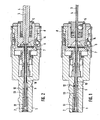
- Minimal lubrication source serving cooling lubricant channel 2 one Connection of the minimal lubrication source with the longitudinal bore 3 of a tap 4, the tap in a quick change insert 5 is clamped.
- This quick-change insert 5 lies with its inner end edge 6 on a sealing ring 7 of the insert sleeve 8 for the quick-change insert 5.
- the coolant-lubricant channel 2 is a thin-walled coolant tube 9 axially longitudinally displaceable stored.
- the coolant-lubricant channel 2 is partially narrowed or inserts that guide bushings closely surrounding the coolant tube form.
- a front guide bearing bush 10 and a rear guide bearing bush 11 formed by an insert intended.
- On the coolant tube 9 is between the two guide bearing bushes 10 and 11 attached an washer 12 to which the front end a helical compression spring 13 is supported, the rear end of which is at the rear Guide bushing 11 supports.
- a helical compression spring 13 that Coolant pipe pushed forward so that it is in a more or less sealing Engagement with the longitudinal bore 3 of the tap is independent of which axial position is the rear end of the tap occupies.
- the washer 12 serves in connection with the front guide bearing bush 10 as a pull-out limitation for the coolant pipe 9. If there is no quick-change insert in the feed shaft, it is located the coolant pipe in its most outwardly displaced position, in which rests the washer 12 on the guide bearing bush 10. Becomes a quick change insert with a tap no matter what diameter used, the inner end of the tap pushes the coolant pipe accordingly far to the rear, either in the position shown in FIG. 1 or in the position shown in FIG. 2 or any intermediate position.
Landscapes
- Engineering & Computer Science (AREA)
- Mechanical Engineering (AREA)
- Physics & Mathematics (AREA)
- Fluid Mechanics (AREA)
- Auxiliary Devices For Machine Tools (AREA)
Description
- Fig. 1
- einen Schnitt durch ein erfindungsgemäßes Schnellwechselfutter mit einem Gewindebohrer kleinen Durchmessers, und
- Fig. 2
- einen Schnitt durch das gleiche Gewindeschneidfutter wie in Fig. 1 mit einem größeren, axial weiter nach hinten reichenden Gewindebohrer.
Claims (4)
- Gewindeschneidfutter für Minimalmengenschmierung mit einem achszentralen Schmiermittelkanal (2) zur Verbindung der Einsatzhülse (8) für die, einen mit einer Längsbohrung (3) versehenen Gewindebohrer (4) aufnehmende, Spannzange, insbesondere einen Schnellwechseleinsatz (5), mit einer maschinenseitigen Minimalschmierquelle, von der das Schmiermittel als Aerosol zur Längsbohrung (3) des Gewindebohrers (4) geführt wird, wobei der Schmiermittelkanal (2) im Einmündungsbereich in die Einsatzhülse (8) ein axial verschiebbares, einen direkten Anschluß an die Längsbohrung des Gewindebohrers herstellendes, Kühlmittelrohr (9) umfaßt, dadurch gekennzeichnet, daß das Kühlmittelrohr (9) einteilig durchgehend vom Gewindebohrer (4) bis zum Schmiermittelzuführkanal (2) des Futterschaftes (1) verlaufend in der Einsatzhülse (8) der Spannzange, insbesondere des Schnellwechseleinsatzes (5), verschiebbar gelagert ist, und daß das Kühlmittelrohr (9) durch den auf seine innere Stirnfläche einwirkenden Druck des Aerosols unabhängig von der Axialposition des Gewindebohrers in seine Eingriffsstellung in die Längsbohrung (3) des Gewindebohrers (4) gedrückt wird.
- Gewindeschneidfutter nach Anspruch 1, dadurch gekennzeichnet, daß das Kühlmittelrohr (9) durch eine Feder nach außen vorgespannt ist.
- Gewindeschneidfutter nach Anspruch 2, dadurch gekennzeichnet, daß eine das Kühlmittelrohr (9) umgebende Wendeldruckfeder (13) sich an einer hinteren Führungslagerbuchse (11) und einer am Kühlmittelrohr (9) befestigten Ringscheibe (12) abstützt.
- Gewindeschneidfutter nach Anspruch 3, dadurch gekennzeichnet, daß die Ringscheibe (12) zusammen mit einer vorderen Führungslagerbuchse (10) eine Auszugsbegrenzung für das Kühlmittelrohr (9) bildet.
Applications Claiming Priority (2)
| Application Number | Priority Date | Filing Date | Title |
|---|---|---|---|
| DE19821186A DE19821186C1 (de) | 1998-05-12 | 1998-05-12 | Gewindeschneidfutter mit Minimalmengenschmierung |
| DE19821186 | 1998-05-12 |
Publications (2)
| Publication Number | Publication Date |
|---|---|
| EP0956919A1 EP0956919A1 (de) | 1999-11-17 |
| EP0956919B1 true EP0956919B1 (de) | 2001-11-14 |
Family
ID=7867491
Family Applications (1)
| Application Number | Title | Priority Date | Filing Date |
|---|---|---|---|
| EP99105214A Expired - Lifetime EP0956919B1 (de) | 1998-05-12 | 1999-03-13 | Gewindeschneidfutter mit Minimalmengenschmierung |
Country Status (3)
| Country | Link |
|---|---|
| US (1) | US6135679A (de) |
| EP (1) | EP0956919B1 (de) |
| DE (2) | DE19821186C1 (de) |
Cited By (1)
| Publication number | Priority date | Publication date | Assignee | Title |
|---|---|---|---|---|
| DE102004021082A1 (de) * | 2004-04-29 | 2005-11-17 | Bilz Werkzeugfabrik Gmbh & Co. Kg | Schnellwechseleinsatz für Werkzeuge, insbesondere für Gewindebohrer |
Families Citing this family (14)
| Publication number | Priority date | Publication date | Assignee | Title |
|---|---|---|---|---|
| DE19835677C5 (de) * | 1998-07-22 | 2010-11-04 | Gühring, Jörg, Dr. | Einrichtung zur Zufuhr von Medien an ein Werkzeug |
| JP3409180B2 (ja) * | 1998-09-11 | 2003-05-26 | ホーコス株式会社 | 工作機械用工具ホルダ |
| US7426822B2 (en) * | 2002-05-23 | 2008-09-23 | Nv Bekaert Sa | Metal cord |
| DE20321113U1 (de) * | 2002-12-11 | 2005-12-29 | E. Zoller GmbH & Co. KG Einstell- und Messgeräte | Werkzeughaltevorrichtung |
| US7090448B2 (en) * | 2004-08-03 | 2006-08-15 | Ford Motor Company | Tool holder assembly |
| DE102004063739B4 (de) * | 2004-12-29 | 2009-04-09 | EMUGE-Werk Richard Glimpel GmbH & Co. KG Fabrik für Präzisionswerkzeuge | Vorrichtung zum Koppeln eines Rotationswerkzeugs mit einer Werkzeugspindel sowie ein Verfahren zum Bearbeiten eines Werkstücks mit einem Rotationswerkzeug |
| DE102005007708A1 (de) * | 2005-02-18 | 2006-08-31 | Zettl GmbH CNC Präzisions- und Sonderwerkzeuge | Gewindebohreraufnahme |
| DE102007012859B4 (de) * | 2007-03-17 | 2009-01-02 | Josef Albrecht Bohrfutterfabrik Gmbh & Co. Kg | Spülbares Futter |
| DE102010037822B4 (de) | 2010-09-10 | 2013-06-27 | EMUGE-Werk Richard Glimpel GmbH & Co. KG Fabrik für Präzisionswerkzeuge | Werkzeugaufnahme zum Einsatz in einer Werkzeugmaschine und Verfahren zum Betreiben einer solchen Werkzeugaufnahme |
| US8853072B2 (en) | 2011-06-06 | 2014-10-07 | Micron Technology, Inc. | Methods of forming through-substrate interconnects |
| DE102012215039A1 (de) * | 2012-04-13 | 2013-10-17 | Gühring Ohg | Werkzeugaufnahme, insbesondere für ein Gewindeerzeugungswerkzeug |
| DE102014104192B3 (de) | 2014-03-26 | 2015-05-28 | Hochschule Furtwangen | Vorrichtung zur Aufnahme eines Werkzeugs |
| US10160042B2 (en) | 2014-04-04 | 2018-12-25 | Kennametal Inc. | Reducer sleeve with thru coolant flow and a cutting assembly using such reducer sleeve |
| US12365035B2 (en) | 2021-12-17 | 2025-07-22 | Kennametal Inc. | Tool holders with fluid directing passages |
Family Cites Families (6)
| Publication number | Priority date | Publication date | Assignee | Title |
|---|---|---|---|---|
| DE2435188A1 (de) * | 1974-07-22 | 1976-02-05 | Fahrion Fa Eugen | Vorrichtung zum kuppeln eines ein einsatzstueck aufnehmenden einsetzkoerpers mit einem antriebskoerper, insbesondere einer ein werkzeug aufnehmenden stellhuelse mit einem in eine spindel einer werkzeugmaschine einsetzbaren schnellwechselfutter |
| US4396317A (en) * | 1981-06-11 | 1983-08-02 | The Bendix Corporation | Tool holder having coolant fluid delivery system |
| GB8424674D0 (en) * | 1984-09-29 | 1984-11-07 | Rotadop Halifax Ltd | Toolholders |
| US4640652A (en) * | 1986-06-30 | 1987-02-03 | Scully-Jones Corp. | Coolant delivery system |
| DE4019760A1 (de) * | 1990-06-21 | 1992-01-09 | Glimpel Emuge Werk | Schnellwechselfutter mit laengenausgleichsvorrichtung und achs-zentraler kuehlmittelzufuehrung |
| DE4218237A1 (de) * | 1992-06-03 | 1993-12-09 | Adolf Wellach | Werkzeughalter |
-
1998
- 1998-05-12 DE DE19821186A patent/DE19821186C1/de not_active Expired - Fee Related
-
1999
- 1999-03-13 EP EP99105214A patent/EP0956919B1/de not_active Expired - Lifetime
- 1999-03-13 DE DE59900415T patent/DE59900415D1/de not_active Expired - Lifetime
- 1999-05-05 US US09/305,508 patent/US6135679A/en not_active Expired - Lifetime
Cited By (2)
| Publication number | Priority date | Publication date | Assignee | Title |
|---|---|---|---|---|
| DE102004021082A1 (de) * | 2004-04-29 | 2005-11-17 | Bilz Werkzeugfabrik Gmbh & Co. Kg | Schnellwechseleinsatz für Werkzeuge, insbesondere für Gewindebohrer |
| US7244080B2 (en) | 2004-04-29 | 2007-07-17 | Bilz Werkzeugfabrik Gmbh & Co. Kg | Quick-change insert for tools, especially for thread drills |
Also Published As
| Publication number | Publication date |
|---|---|
| US6135679A (en) | 2000-10-24 |
| EP0956919A1 (de) | 1999-11-17 |
| DE59900415D1 (de) | 2001-12-20 |
| DE19821186C1 (de) | 2000-03-02 |
Similar Documents
| Publication | Publication Date | Title |
|---|---|---|
| EP0956919B1 (de) | Gewindeschneidfutter mit Minimalmengenschmierung | |
| DE112010004240B4 (de) | Werkzeughalter sowie Kühlmittelkupplungsystem bestehend aus einem Werkzeughalter und einem Werkzeughalterstützglied | |
| EP0956920B2 (de) | Futter für drehantreibbare Werkzeuge, insbesondere Bohrer, Gewindebohrer o.dgl. | |
| DE102014100763B4 (de) | Kühlmittelsprühdüse und Fräswerkzeugbaugruppe | |
| DE10100719A1 (de) | Spannfutter zum Spannen von Werkzeugen durch Schrumpfsitz | |
| EP1266709A1 (de) | Werkzeug | |
| DE102010013430A1 (de) | Spannfutter für Werkzeuge | |
| EP1072356B1 (de) | Zuführung für Medien an ein Werkzeug | |
| DE19861306B4 (de) | Vorrichtung zur Einspeisung von Kühl- und Schmiermittel in ein Werkzeug | |
| DE102010002669A1 (de) | Drehantreibbares spanabhebendes Werkzeug | |
| DE112006002010B4 (de) | Vorrichtung zur Kühlmitteleinspeisung in einen Schaft eines Rundlaufwerkzeugs sowie ein Rundlaufwerkzeug, insbesondere Bohrer | |
| DE19815134B4 (de) | Spindelkopf für Werkzeugmaschinen | |
| DE3419417A1 (de) | Fuehrungsvorrichtung fuer eine werkstoffstange in einer drehmaschine | |
| EP1934008B1 (de) | Werkzeugspannfutter, das für ein automatisches spannen mittels einer automatikspindel an einer maschine ausgelegt ist | |
| DE10331769B4 (de) | Spannfutter | |
| EP1593454B1 (de) | Schnellwechseleinsatz für Werkzeuge, insbesondere für Gewindebohrer | |
| DD297089A5 (de) | Werkzeug fuer den einsatz in werkzeugmaschinen | |
| DE102023103626A1 (de) | Einlippenbohrer mit auswechselbaren Führungsleisten für kleine Bohrungsdurchmesser | |
| DE10351327A1 (de) | Bohrwerkzeug | |
| DE102004063739B4 (de) | Vorrichtung zum Koppeln eines Rotationswerkzeugs mit einer Werkzeugspindel sowie ein Verfahren zum Bearbeiten eines Werkstücks mit einem Rotationswerkzeug | |
| EP1159105A1 (de) | Spannfutter | |
| DE9109821U1 (de) | Dehnspannfutter | |
| EP0434023A2 (de) | Spannzangenfutter mit innerer Kühlmittelzufuhr zum Gewindeschneiden | |
| DE10121986B4 (de) | Mehrschneiden-Reibahle mit innerer Kühlmittelzufuhr | |
| DE2553035A1 (de) | Kernbohrwerkzeug |
Legal Events
| Date | Code | Title | Description |
|---|---|---|---|
| PUAI | Public reference made under article 153(3) epc to a published international application that has entered the european phase |
Free format text: ORIGINAL CODE: 0009012 |
|
| AK | Designated contracting states |
Kind code of ref document: A1 Designated state(s): DE FR GB IT |
|
| AX | Request for extension of the european patent |
Free format text: AL;LT;LV;MK;RO;SI |
|
| 17P | Request for examination filed |
Effective date: 19991020 |
|
| AKX | Designation fees paid |
Free format text: DE FR GB IT |
|
| GRAG | Despatch of communication of intention to grant |
Free format text: ORIGINAL CODE: EPIDOS AGRA |
|
| GRAG | Despatch of communication of intention to grant |
Free format text: ORIGINAL CODE: EPIDOS AGRA |
|
| GRAH | Despatch of communication of intention to grant a patent |
Free format text: ORIGINAL CODE: EPIDOS IGRA |
|
| 17Q | First examination report despatched |
Effective date: 20010424 |
|
| GRAH | Despatch of communication of intention to grant a patent |
Free format text: ORIGINAL CODE: EPIDOS IGRA |
|
| GRAA | (expected) grant |
Free format text: ORIGINAL CODE: 0009210 |
|
| AK | Designated contracting states |
Kind code of ref document: B1 Designated state(s): DE FR GB IT |
|
| REF | Corresponds to: |
Ref document number: 59900415 Country of ref document: DE Date of ref document: 20011220 |
|
| REG | Reference to a national code |
Ref country code: GB Ref legal event code: IF02 |
|
| GBT | Gb: translation of ep patent filed (gb section 77(6)(a)/1977) |
Effective date: 20020118 |
|
| PLBE | No opposition filed within time limit |
Free format text: ORIGINAL CODE: 0009261 |
|
| STAA | Information on the status of an ep patent application or granted ep patent |
Free format text: STATUS: NO OPPOSITION FILED WITHIN TIME LIMIT |
|
| 26N | No opposition filed | ||
| PG25 | Lapsed in a contracting state [announced via postgrant information from national office to epo] |
Ref country code: IT Free format text: LAPSE BECAUSE OF NON-PAYMENT OF DUE FEES Effective date: 20050313 |
|
| PGRI | Patent reinstated in contracting state [announced from national office to epo] |
Ref country code: IT Effective date: 20091001 |
|
| PGFP | Annual fee paid to national office [announced via postgrant information from national office to epo] |
Ref country code: GB Payment date: 20130207 Year of fee payment: 15 |
|
| GBPC | Gb: european patent ceased through non-payment of renewal fee |
Effective date: 20140313 |
|
| PG25 | Lapsed in a contracting state [announced via postgrant information from national office to epo] |
Ref country code: GB Free format text: LAPSE BECAUSE OF NON-PAYMENT OF DUE FEES Effective date: 20140313 |
|
| REG | Reference to a national code |
Ref country code: FR Ref legal event code: PLFP Year of fee payment: 17 |
|
| PGFP | Annual fee paid to national office [announced via postgrant information from national office to epo] |
Ref country code: FR Payment date: 20150319 Year of fee payment: 17 |
|
| REG | Reference to a national code |
Ref country code: FR Ref legal event code: ST Effective date: 20161130 |
|
| PG25 | Lapsed in a contracting state [announced via postgrant information from national office to epo] |
Ref country code: FR Free format text: LAPSE BECAUSE OF NON-PAYMENT OF DUE FEES Effective date: 20160331 |
|
| PGFP | Annual fee paid to national office [announced via postgrant information from national office to epo] |
Ref country code: DE Payment date: 20180321 Year of fee payment: 20 |
|
| PGFP | Annual fee paid to national office [announced via postgrant information from national office to epo] |
Ref country code: IT Payment date: 20180322 Year of fee payment: 20 |
|
| REG | Reference to a national code |
Ref country code: DE Ref legal event code: R071 Ref document number: 59900415 Country of ref document: DE |