EP0956844A2 - Element pour rigidifier un article absorbant et son procédé de fabrication - Google Patents
Element pour rigidifier un article absorbant et son procédé de fabrication Download PDFInfo
- Publication number
- EP0956844A2 EP0956844A2 EP99850077A EP99850077A EP0956844A2 EP 0956844 A2 EP0956844 A2 EP 0956844A2 EP 99850077 A EP99850077 A EP 99850077A EP 99850077 A EP99850077 A EP 99850077A EP 0956844 A2 EP0956844 A2 EP 0956844A2
- Authority
- EP
- European Patent Office
- Prior art keywords
- forming element
- corrugations
- end portion
- accordance
- exhibits
- Prior art date
- Legal status (The legal status is an assumption and is not a legal conclusion. Google has not performed a legal analysis and makes no representation as to the accuracy of the status listed.)
- Granted
Links
Images


Classifications
-
- A—HUMAN NECESSITIES
- A61—MEDICAL OR VETERINARY SCIENCE; HYGIENE
- A61F—FILTERS IMPLANTABLE INTO BLOOD VESSELS; PROSTHESES; DEVICES PROVIDING PATENCY TO, OR PREVENTING COLLAPSING OF, TUBULAR STRUCTURES OF THE BODY, e.g. STENTS; ORTHOPAEDIC, NURSING OR CONTRACEPTIVE DEVICES; FOMENTATION; TREATMENT OR PROTECTION OF EYES OR EARS; BANDAGES, DRESSINGS OR ABSORBENT PADS; FIRST-AID KITS
- A61F13/00—Bandages or dressings; Absorbent pads
- A61F13/15—Absorbent pads, e.g. sanitary towels, swabs or tampons for external or internal application to the body; Supporting or fastening means therefor; Tampon applicators
- A61F13/45—Absorbent pads, e.g. sanitary towels, swabs or tampons for external or internal application to the body; Supporting or fastening means therefor; Tampon applicators characterised by the shape
- A61F13/47—Sanitary towels, incontinence pads or napkins
- A61F13/4702—Sanitary towels, incontinence pads or napkins having a reinforcing member
Definitions
- the invention concerns a forming element for an absorbent article, such as a sanitary napkin, an incontinence protector or a panty shield, which forming element is formed of a rigid material and exhibits a principally elongate form with a longitudinal direction and a transverse direction, an upper side, an underside, two short sides and two long sides, a first and a second end portion and an intermediate portion.
- the invention further concerns an absorbent article, such as a sanitary napkin, an incontinence protector or a panty shield, which article has a principally elongate form with two end portions and an intermediate portion situated between the end portions.
- an absorbent article such as a sanitary napkin, an incontinence protector or a panty shield, which article has a principally elongate form with two end portions and an intermediate portion situated between the end portions.
- Absorbent articles such as sanitary napkins, incontinence protectors and panty shields are subjected during use to great forces, for example when the user is walking.
- the absorbent article is then sheared between the thighs of the user.
- a conventional absorbent article is usually manufactured in soft materials, which wrinkle under the effect of these forces. Wrinkles result in a reduction of the reception area on the article for liquid which is emitted from the user.
- the wrinkles form channels in which liquid on the surface of the article can run out towards and over the edges of the article. In other words, there is an increased risk of leakage.
- absorbent articles such as sanitary napkins
- glue glue
- the article follows the movements of the underclothes rather than the body movements of the user. Displacements and gaps between the body of the user and the article can lead to the available reception area becoming insufficient. Moreover, liquid can leak out between the article and the body of the user.
- the forming element In order to function as intended and to make the absorbent article shape stable, the forming element must be made of a rigid material and exhibit a sufficient thickness. If the forming element has a high thickness the total weight of the absorbent article will also be high. A high weight of the absorbent article can lead to problems, for instance concerning transport and user comfort.
- a purpose of the present invention is therefore to obtain a forming element with low weight but necessary rigidity and an absorbent article containing such a forming element.
- the article preferably exhibits a ridge-like raised portion arranged on the upper side of the forming element in the longitudinal direction of the forming element in the second end portion.
- the invention can be further characterised in that the corrugations are arranged in the first end portion, in the second end portion, which is intended to face backwards on the user during use, or in both end portions.
- the corrugations are arranged as elongate raised portions or depressions on the upper side of the forming element and exhibit a longitudinal direction and a transverse direction, wherein the corrugations are arranged with their longitudinal direction principally in the transverse direction of the forming element.
- the forming element according to the invention can be further characterised in that the widest part on the first end portion is 1.5 - 5 times as wide as the narrowest width on the intermediate portion.
- the invention also concerns an absorbent article comprising a forming element in accordance with what is stated above.
- a forming element according to the above-mentioned PCT/SE97/01881 is manufactured of a rigid layer, for example a plastic layer.
- a rigid layer for example a plastic layer.
- Polystyrene or mineral-filled polypropylene with a layer thickness of at least 0.4 mm can be mentioned as examples of plastic materials which are stated as having sufficient rigidity and torsion rigidity to reach the necessary shape stability.
- the shape stability of a forming element of the kind intended here must be sufficiently great to essentially enable the article to retain a predetermined and predictable form during use.
- the material stiffness of the layer material that is used in the forming element is of course significant to the shape stability of the forming element.
- Plastic materials with a stiffness coefficient of at least 1500 Mpa measured according to ISO 178 have been found to be usable
- the shape stability of the forming element is determined not only by the material stiffness of the forming element but also by the shape of the forming element; the existence and location of corrugations in the forming element, especially, affect the shape stability.
- a forming element in accordance with the invention can be formed of a plastic layer that is from ca. 0.2 to ca. 0.4 mm, since it is provided with stiffening corrugations. Depending on the location and form of the corrugations, it can even, in certain cases, be possible to use plastic layers of a lesser thickness than 0.2 mm.
- the term corrugations denotes portions of a layer material which project out from the main plane of the material. The corrugations must be arranged in a direction that is parallel with the deformation forces that are to be counteracted by the corrugations. For example, transverse compression of an absorbent article is counteracted by arranging transverse corrugations, i.e. corrugations that extend in the transverse direction of the article.
- Corrugations are arranged in the forming element to create a greater rigidity and thereby shape stability within the portions of the forming element where high shape stability is critical to the fit and attachment of an absorbent article of which the forming element is a part.
- An absorbent article of the type which is intended during use to essentially be accommodated in the crotch area of the user exhibits two end portions, intended to be directed backwards and forwards, respectively, on the user. Between the end portions there is an intermediate portion, which constitutes the transition between the two end portions and is narrower than these.
- the proportions between the various portions can vary somewhat between different articles, for example depending on the size of the article.
- the forward end portion is preferably ca. 1.5 - 5 times broader than the intermediate portion in order to prevent the article from shifting backwards on the user during use.
- the stiffening corrugations which, in accordance with the invention, are arranged in the forming element of the article, are principally arranged in the end portions of the article.
- the corrugations in the forming element can be arranged only in the first or only in the second end portion. Alternatively, and preferably, the corrugations can be present in both end portions. In order to achieve a good effect with corrugations arranged only in one of the end portions, it can be suitable to form the forming element of a material with greater thickness in the end portion without corrugations. The thickness of the end portion without corrugations should then be greater than ca. 0.4 mm. However, such an embodiment is less preferable as it is more difficult to manufacture and gives the article a greater weight and reduced comfort.
- the corrugations can be formed as elongate raised portions or depressions in the upper side of the forming element.
- the term the upper side of the forming element relates to that side of the forming element which, when it is arranged in an absorbent article, is intended to face towards the body of the user during use.
- the corrugations can also be formed as raised or depressed continuous areas with another suitable form. It has been shown that a plurality of separate corrugations arranged over a certain area on the forming element give a greater stiffening effect than arranging one continuous corrugation over a corresponding area.
- the corrugations in the first end portion can be constituted of a raised or depressed area with a surface of ca. 5 x 3 cm 2 ⁇ 5 cm 2 .
- the corrugations can also be constituted of two or more elongate raised portions or depressions in the upper side of the forming element. These are arranged with their longitudinal direction principally in the transverse direction of the forming element.
- the corrugations can be separate or continuous in a curve, for example in an S-shape.
- the first end portion of the forming element is preferably formed with increasing width towards the short end of the forming element.
- the length of the corrugations follows the width of the end portion, i.e. they are longer the nearer they are located to the short side of the forming element.
- the elongate corrugations suitably have a height, or a depth, measured from the plane of the forming element that is from ca. 1.5 to 5 mm and a width that is from ca. 0.3 mm to 10 mm, preferably ca. 0.5 mm.
- the length can vary within fairly wide limits and can be from ca. 0.8 cm to 8 cm.
- the corrugations do not require to have the same height along their entire length; the height can vary.
- the corrugations can be higher at the outer edges of the forming element and lower therebetween, or vice versa.
- the corrugations in the second end portion exhibiting the ridge-like raised portion can be constituted of a continuous raised area symmetrically arranged on either side of the ridge-like raised portion.
- the corrugations can also be formed as elongate raised portions with their longitudinal direction principally in the transverse direction of the forming element, i.e. extending across the ridge-like raised portion.
- the elongate corrugations in the second end portion can be, for example, 3-10 in number and can extend on one or both sides of the ridge-like raised portion.
- Such elongate corrugations suitably have a height or a depth that is ca. 1.5-5 mm, a width that is ca. 0.3-10 mm and a length that is ca. 0.8-20 mm.
- a deformation zone in the forming element is obtained nearest the edge.
- Such an embodiment can be advantageous from the point of view of comfort but can also be utilised to achieve a forming effect.
- transverse corrugations arranged in the first portion of the forming element i.e. that portion which is intended to be directed forwards on a user during use, can, in this way, be used to create an indication to form a cup-shape during use.
- the length of the corrugations follows the contour of the forming element, i.e. a corrugation is longer in the wider part of the forming element and shorter in the narrower part.
- an article containing such a forming element can be formed flat and can then be given an anatomically correct form under the influence of the compressing forces to which the article is subjected during use.
- An article that is formed in this manner during use is described in SE 9702463-2.
- the forming element By arranging the corrugations in the first end portion so that they follow the contour of the forming element and by making the corrugations end a distance within the side edge of the forming element, the forming element will be perfectly formed to a cup around the mons veneris of the user during use.
- An absorbent article in accordance with the invention preferably exhibits a central longitudinal raised portion in that end portion which is intended to be directed backwards on a user during use.
- a raised portion can be wholly or partially formed by the forming element.
- the raised portion can be wholly or partially constructed of other materials, for example absorbent materials. It is also possible to create raised portions that are not activated until the article is used, by means of folding indications in the forming element and/or the absorbent body of the absorbent article.
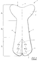
- Fig. 1 shows a forming element 1 in accordance with the invention.
- the forming element exhibits a principally elongate form with a longitudinal direction and a transverse direction, an upper side 2, an underside 3, two short sides 4, 5 and two long sides 6, 7 a first and a second end portion 8, 9, an intermediate portion 10 and a ridge-like raised portion 11 arranged on the upper side 2 in the longitudinal direction of the forming element in second end portion 9.
- the forming element further exhibits a corrugation 12 in the first end portion 8.
- the corrugation 12 consists of a raised area on the upper side 2 of the forming element and has the form of a parallel trapezium.
- the form of the corrugation 12 is adapted to the form on the outer contour of the forming element 1, i.e. the longest transverse edge on the corrugation is situated nearest the short side 4 of the forming element, where the forming element is widest.
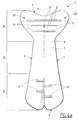
- Fig. 2 shows a forming element 1 in accordance with an alternative embodiment of the invention.
- the forming element 1 exhibits here a corrugation 13 in the second end portion 9.
- the corrugation 13 is constituted by a raised portion in the form of an area which is symmetrically formed around the ridge-like raised portion 11.
- the corrugation 13 has symmetrical projections on either side of the ridge-like raised portion 11 and has principally the form of a Christmas tree.
- the forming element can have, for example, a length that is ca. 200 mm measured along a longitudinal central line, a, of the forming element.
- Longitudinal central line denotes a line in the longitudinal direction of the forming element, which is situated at an equal distance from the longitudinal edges of the forming element.
- the first end portion constitutes ca. 50 mm of it, the second end portion constitutes ca. 100 mm of it and the intermediate portion constitutes ca. 50 mm of the total length of the forming element.
- the first end portion 8 exhibits a heart-shape with a width which increases in a direction towards the short side of the forming element. Where the first end portion is narrowest, in the transition between the intermediate portion 10 and the end portion 8, the first end portion is ca.
- the first end portion is ca. 90 mm wide.
- the intermediate portion 10 is narrowest in the transition between it and the first end portion 8 and is ca. 20 mm wide there, increasing in width towards the second end portion 9 where the width of the intermediate portion 10 is ca. 30 mm at its widest.
- the width of the second end portion 9 in the part which borders on the intermediate portion 10 is consequently ca. 30 mm.
- the width of the second end portion 9 increases from the intermediate portion 10 towards the short side of the forming element for ca. 2/3 of the length of the end portion 9 then having a more or less constant width of ca. 65 mm for the final third.
- the rear widening of the forming element helps to prevent the article from slipping forwards between the legs of the user.
- the second end portion 9 exhibits an indentation in the side which faces towards the short side 4 of the article.
- the purpose of this indentation is to make the article more comfortable for the user as too long an extension of the forming element in the rear end can cause discomfort and make the article less discrete.
- plastic material requires to have a certain minimum stiffness.
- Plastic layers with a stiffness coefficient of at least 1500 Mpa measured according to ISO 178 have been found to work well. Examples of plastic materials that can be used are polystyrene and mineral-filled polypropylene.
- corrugations 12, 13 are arranged in the end portions 8, 9 of the forming element 1, sufficient shape stability can be achieved for plastic layers with a thickness less than ca. 0.4 mm and preferably over 0.2 mm.
- a thinner plastic material generally requires more and/or larger corrugations within a certain area in order to achieve a sufficient stiffening effect. Sufficient shape stability and deformation resistance are considered to be present if the absorbent article can be held in place against the body of the user during use without special attachment arrangements.
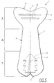
- Fig. 3 shows a further embodiment of the invention.
- the forming element 1 exhibits corrugations 12, 13 in the first end portion 8 and the second end portion 9.
- the corrugation 12 in the first end portion 8 consists of a parallel trapezium-shaped, raised area on the upper side 2 of the forming element.
- the corrugations 13 in the second end portion 9 are constituted of three elongate raised portions in the upper side 2 of the forming element.
- the raised portions are arranged on either side of the ridge-like raised portion 11, with the longitudinal direction of the corrugations 13 arranged principally in the transverse direction of the forming element.
- Figs. 4a and 4b show two somewhat different embodiments of the invention in which the forming element 1 exhibits corrugations 12 in the first end portion 8.
- the corrugations are constituted of three elongate depressions in the upper side 2 of the forming element, while the corrugations 12 in Fig. 4b are constituted of three elongate raised portions.
- the corrugations 12 are arranged with their longitudinal direction in the transverse direction of the forming element.
- the length of the corrugations is adapted to the width of the first end portion. That is to say, as the width of the end portion diminishes in a direction from the short side 4 of the forming element towards the intermediate portion 10, the corrugations 12 become shorter the nearer they are situated to the intermediate portion 10.
- a particular advantage of arranging the corrugations 12 in a pattern of the kind shown in Figs. 4a and 4b is that, in addition to forming stiffening members which counteract undesired deformation of the central part of the first end portion 8, the corrugations 12 also serve as forming members to build a cup-shape which can conform to the contours of the mons veneris of the user during use. Such a cup-shape is shown in Fig. 4b. As the corrugations 12 only extend in the transverse direction over the central part 22 of the first end portion 8, less stiff edge portions 20 are left free of corrugations at the first short side 4 and long sides 6, 7 of the forming element 1.
- the end edges 21 of the corrugations 12 serve as folding indications for the edge portions 20 so that these can be folded up from the upper side 2 of the forming element 1 and form cupped walls around the central part of the first end part 8.
- the corrugation-free edge portions 20 of the forward end portion 8 should have a width between the end edges 21 of the corrugations and the long sides 6, 7 of the first end portion 8 that is at least ca. 5 mm and preferably between ca. 7 mm and 25 mm.
- the second end portion 9 exhibits four corrugations 13 in the form of elongate raised portions, two of which are arranged on one side of the ridge-like raised portion and two on the other side of the raised portion.
- the corrugations are arranged with their longitudinal direction in the transverse direction of the forming element.
- Fig. 4b shows an alternative embodiment of the second end portion 9 of the forming element with a central, ridge-like raised portion 11, which is elongated in the direction towards the intermediate portion 10 and from which transverse, raised corrugations 13 extend. It can be noted that the height of the central raised portion 11 varies in the longitudinal direction of the forming element 1.
- Fig. 5 shows a further embodiment of the invention.
- Fig. 5 describes a forming element 1 which exhibits corrugations 12 in the form of two elongate raised portions in the first end portion 8 and one corrugation 13 in the form of a symmetrically formed raised area around the ridge-like raised portion 11,
- the corrugation 13 has symmetrical protrusions and has approximately the shape of a Christmas tree.
- the sanitary napkin 14 shown in Fig. 6 comprises a liquid-permeable surface layer 15 arranged on that side of the sanitary napkin 14 which is intended to face towards the user during use and a liquid-barrier layer 16 arranged on the side of the sanitary napkin 14 which is intended to face away from the user during use. Between the surface layer 15 and the liquid-barrier rear side layer 16 an absorbent layer 17 is arranged.
- the material in the surface layer 15 can be, for example, a perforated plastic film, a net of plastic or textile material, a nonwoven material or a laminate of, for example, a perforated plastic layer and a nonwoven layer.
- the plastic can be a thermoplastic, such as polyethylene.
- the nonwoven material can comprise natural fibres, such as cellulose or cotton, synthetic fibres, such as polyethylene, polypropylene, polyester, polyurethane, nylon or regenerated cellulose.
- the main tasks of the surface layer 15 in the sanitary napkin are to lead liquid in to the absorbent layer 17, to be soft and comfortable against the body of the user and to prevent rewetting, i.e absorbed body fluid penetrating back towards the skin of the user.
- rewetting i.e absorbed body fluid penetrating back towards the skin of the user.
- it is important that the surface of that part of the sanitary napkin that lies against the skin of the user is maintained as dry as possible during use.
- a dry surface on the sanitary napkin is perceived by the user as cooler and more comfortable during use and is also, purely visually and during handling when the sanitary napkin is to be changed, more attractive than a soiled, wet surface.
- the liquid-barrier layer, or rear side layer 16 consists of a liquid-impermeable material.
- Thin liquid-impermeable plastic films are suitable for the purpose but it is also possible to use material which is initially liquid-permeable but which has been provided with a coating of plastic, resin or other material which resists liquid penetration. By this means, leakage of liquid from the underside of the absorbent article is prevented.
- the barrier layer 3 can accordingly consist of any material which fulfils the criterion of liquid-impermeability, and also exhibits sufficient skin-friendliness for the purpose. Examples of materials which are suitable as barrier layers are plastic films, nonwovens and laminates of these.
- the plastic film can be, for example, of polyethylene, polypropylene or polyester.
- the barrier layer can consist of a laminate of a liquid-impermeable plastic film, facing towards the absorbent body, and a nonwoven material, facing towards the underclothes of the user.
- a construction gives a leakproof barrier layer with a textile feel.
- the forming element 1 it is then suitable to arrange a soft textile or textile-like material layer on the outside of the forming element.
- the absorbent layer 17 is suitably manufactured of cellulose pulp. It can originally be in rolls, bales or sheets which during the manufacture of the sanitary napkin are dry defibrated and transferred in fluffed form to a pulp web, sometimes mixed with superabsorbents, which are polymers with the ability to absorb several times their own weight of water or body fluid. An alternative to this is to dry form a pulp web, as is described in WO 94/10956. Examples of other absorbent materials which can be used are various types of natural fibres, such as cotton fibres, peat moss, or the like. Naturally, it is also possible to utilise absorbent synthetic fibres or mixtures of natural fibres and synthetic fibres.
- the absorbent material can contain further components, such as form-stabilising members, liquid-distributing members or binding agents, such as thermoplastic fibres which have been heat-treated to hold together short fibres and particles into a coherent unit. It is also possible to use various types of absorbent foam material in the absorbent layer.
- the sanitary napkin 14 exhibits a forming element 1 in accordance with the invention.
- the forming element exhibits three elongate corrugations 12 in the form of depressions in the first end portion 8 and four elongate corrugations 13, two of which are situated on either side of the ridge-like raised portion 11 and extending principally in the transverse direction of the forming element and the sanitary napkin.
- the surface layer 15 and the rear side layer 16 are joined in a glued joint 18 outside the edge of the forming element 1 and the absorbent layer 17.
- Figs. 7a-c show sections along the lines Vlla-Vlla, Vllb-Vllb and Vllc-Vllc through the sanitary napkin in Fig. 6. Accordingly, Fig. 7 shows the absorbent layer situated in the intermediate portion 10 and the second end portion 9. In the first end portion 8 there are only the surface layer 15, the rear side layer 16 and the forming element 1. Of course, it is possible to arrange the absorbent layer in alternative ways, such as within only the intermediate portion 10, or over the entire sanitary napkin 14.
Applications Claiming Priority (2)
| Application Number | Priority Date | Filing Date | Title |
|---|---|---|---|
| SE9801666A SE517717C2 (sv) | 1998-05-12 | 1998-05-12 | Ett formelement med korrugeringar samt ett absorberande alster med ett sådant formelement |
| SE9801666 | 1998-05-12 |
Publications (3)
| Publication Number | Publication Date |
|---|---|
| EP0956844A2 true EP0956844A2 (fr) | 1999-11-17 |
| EP0956844A3 EP0956844A3 (fr) | 2001-06-20 |
| EP0956844B1 EP0956844B1 (fr) | 2006-07-26 |
Family
ID=20411286
Family Applications (1)
| Application Number | Title | Priority Date | Filing Date |
|---|---|---|---|
| EP99850077A Expired - Lifetime EP0956844B1 (fr) | 1998-05-12 | 1999-05-07 | Element pour rigidifier un article absorbant et son procédé de fabrication |
Country Status (5)
| Country | Link |
|---|---|
| US (1) | US6579272B1 (fr) |
| EP (1) | EP0956844B1 (fr) |
| AT (1) | ATE333855T1 (fr) |
| DE (1) | DE69932468T2 (fr) |
| SE (1) | SE517717C2 (fr) |
Cited By (10)
| Publication number | Priority date | Publication date | Assignee | Title |
|---|---|---|---|---|
| WO2003047484A1 (fr) * | 2001-12-06 | 2003-06-12 | Sca Hygiene Products Ab | Article absorbant a ajustement ameliore |
| WO2003047483A1 (fr) * | 2001-12-06 | 2003-06-12 | Sca Hygiene Products Ab | Article absorbant avec ajustement ameliore |
| WO2003053301A1 (fr) * | 2001-12-06 | 2003-07-03 | Sca Hygiene Products Ab | Article absorbant a ajustement ameliore |
| WO2003059222A1 (fr) * | 2001-12-06 | 2003-07-24 | Sca Hygiene Products Ab | Article absorbant a accessoire ameliore |
| US7156832B2 (en) | 2001-12-06 | 2007-01-02 | Sca Hygiene Products Ab | Absorbent Article having a stiffening element and elongate through-hole |
| US7601144B2 (en) | 2001-12-06 | 2009-10-13 | Sca Hygiene Products Ab | Absorbent article with improved fit |
| US7825291B2 (en) | 2005-07-13 | 2010-11-02 | Sca Hygiene Products Ab | Absorbent article having absorbent core including regions of lower thickness |
| US8029487B2 (en) | 2006-07-05 | 2011-10-04 | Sca Hygiene Products Ab | Absorbent article with improved fit and leakage security |
| US8153856B2 (en) | 2005-07-13 | 2012-04-10 | Sca Hygiene Products Ab | Absorbent article having absorbent core including regions of lower density |
| US8901368B2 (en) | 2007-12-07 | 2014-12-02 | Sca Hygiene Products Ab | Absorbent core comprising multiple sublayers |
Families Citing this family (5)
| Publication number | Priority date | Publication date | Assignee | Title |
|---|---|---|---|---|
| US20050065854A1 (en) * | 2003-09-23 | 2005-03-24 | Sca Hygiene Products Ab | Methods and apparatuses for informing, surveying and marketing to potential customers |
| US8167862B2 (en) * | 2004-05-24 | 2012-05-01 | The Procter And Gamble Company | Absorbent article having a fit guide |
| JP4554274B2 (ja) * | 2004-05-27 | 2010-09-29 | ユニ・チャーム株式会社 | 生理用ナプキン |
| JP4312113B2 (ja) * | 2004-07-09 | 2009-08-12 | ユニ・チャーム株式会社 | 生理用ナプキン |
| KR101849439B1 (ko) * | 2011-11-08 | 2018-04-16 | 킴벌리-클라크 월드와이드, 인크. | 안정화 부재를 갖는 흡수 용품 |
Citations (5)
| Publication number | Priority date | Publication date | Assignee | Title |
|---|---|---|---|---|
| WO1998022057A1 (fr) | 1996-11-15 | 1998-05-28 | Sca Hygiene Products Ab | Article absorbant tres rigide |
| WO1998022058A1 (fr) | 1996-11-15 | 1998-05-28 | Sca Hygiene Products Ab | Article absorbant tel qu'une serviette hygienique, une protection contre l'incontinence, une garniture de slip ou analogue |
| WO1998022062A1 (fr) | 1996-11-15 | 1998-05-28 | Sca Hygiene Products Ab | Article absorbant dont une zone est surelevee |
| WO1998022061A1 (fr) | 1996-11-15 | 1998-05-28 | Sca Hygiene Products Ab | Article absorbant tel qu'une serviette hygienique, une protection contre l'incontinence, une garniture de slip ou analogue |
| GB2326598A (en) | 1997-06-26 | 1998-12-30 | Moelnlycke Ab | A sanitary napkin |
Family Cites Families (9)
| Publication number | Priority date | Publication date | Assignee | Title |
|---|---|---|---|---|
| US4685914A (en) * | 1983-09-23 | 1987-08-11 | Personal Products Company | Disposable urinary pad |
| US5171302A (en) * | 1988-03-31 | 1992-12-15 | The Procter & Gamble Company | Absorbent article with central hinge |
| ATE142468T1 (de) * | 1991-07-23 | 1996-09-15 | Procter & Gamble | Dehnbarer saugfaehiger gegenstand |
| US5591150A (en) * | 1991-07-23 | 1997-01-07 | The Procter And Gamble Company | Sanitary napkin having a resilient body-conforming portion |
| SE508961C2 (sv) | 1992-11-17 | 1998-11-23 | Sca Hygiene Prod Ab | Absorberande struktur och absorberande alster innehållande strukturen ifråga |
| US5607415A (en) * | 1994-08-18 | 1997-03-04 | Kimberly-Clark Corporation | Flexible absorbent article |
| ES2160180T3 (es) * | 1994-10-31 | 2001-11-01 | Mcneil Ppc Inc | Articulo absorbente que se arquea y dilata. |
| SE509841C2 (sv) * | 1995-10-04 | 1999-03-15 | Sca Hygiene Prod Ab | Absorberande produkt såsom en absorberande byxa, blöja, inkontinensskydd, dambinda, trosskydd, förband eller liknande |
| JP3499375B2 (ja) * | 1996-07-02 | 2004-02-23 | ユニ・チャーム株式会社 | 吸収シートおよびその製造方法 |
-
1998
- 1998-05-12 SE SE9801666A patent/SE517717C2/sv not_active IP Right Cessation
-
1999
- 1999-05-07 EP EP99850077A patent/EP0956844B1/fr not_active Expired - Lifetime
- 1999-05-07 AT AT99850077T patent/ATE333855T1/de not_active IP Right Cessation
- 1999-05-07 DE DE69932468T patent/DE69932468T2/de not_active Expired - Lifetime
- 1999-05-11 US US09/309,283 patent/US6579272B1/en not_active Expired - Fee Related
Patent Citations (5)
| Publication number | Priority date | Publication date | Assignee | Title |
|---|---|---|---|---|
| WO1998022057A1 (fr) | 1996-11-15 | 1998-05-28 | Sca Hygiene Products Ab | Article absorbant tres rigide |
| WO1998022058A1 (fr) | 1996-11-15 | 1998-05-28 | Sca Hygiene Products Ab | Article absorbant tel qu'une serviette hygienique, une protection contre l'incontinence, une garniture de slip ou analogue |
| WO1998022062A1 (fr) | 1996-11-15 | 1998-05-28 | Sca Hygiene Products Ab | Article absorbant dont une zone est surelevee |
| WO1998022061A1 (fr) | 1996-11-15 | 1998-05-28 | Sca Hygiene Products Ab | Article absorbant tel qu'une serviette hygienique, une protection contre l'incontinence, une garniture de slip ou analogue |
| GB2326598A (en) | 1997-06-26 | 1998-12-30 | Moelnlycke Ab | A sanitary napkin |
Cited By (13)
| Publication number | Priority date | Publication date | Assignee | Title |
|---|---|---|---|---|
| AU2002353724B2 (en) * | 2001-12-06 | 2008-03-06 | Sca Hygiene Products Ab | Absorbent article with improved fit |
| WO2003047483A1 (fr) * | 2001-12-06 | 2003-06-12 | Sca Hygiene Products Ab | Article absorbant avec ajustement ameliore |
| WO2003053301A1 (fr) * | 2001-12-06 | 2003-07-03 | Sca Hygiene Products Ab | Article absorbant a ajustement ameliore |
| WO2003059222A1 (fr) * | 2001-12-06 | 2003-07-24 | Sca Hygiene Products Ab | Article absorbant a accessoire ameliore |
| US7156832B2 (en) | 2001-12-06 | 2007-01-02 | Sca Hygiene Products Ab | Absorbent Article having a stiffening element and elongate through-hole |
| AU2002367005B2 (en) * | 2001-12-06 | 2008-03-06 | Sca Hygiene Products Ab | Absorbent article with improved fit |
| WO2003047484A1 (fr) * | 2001-12-06 | 2003-06-12 | Sca Hygiene Products Ab | Article absorbant a ajustement ameliore |
| AU2002354389B2 (en) * | 2001-12-06 | 2008-04-03 | Sca Hygiene Products Ab | Absorbent article with improved fit |
| US7601144B2 (en) | 2001-12-06 | 2009-10-13 | Sca Hygiene Products Ab | Absorbent article with improved fit |
| US7825291B2 (en) | 2005-07-13 | 2010-11-02 | Sca Hygiene Products Ab | Absorbent article having absorbent core including regions of lower thickness |
| US8153856B2 (en) | 2005-07-13 | 2012-04-10 | Sca Hygiene Products Ab | Absorbent article having absorbent core including regions of lower density |
| US8029487B2 (en) | 2006-07-05 | 2011-10-04 | Sca Hygiene Products Ab | Absorbent article with improved fit and leakage security |
| US8901368B2 (en) | 2007-12-07 | 2014-12-02 | Sca Hygiene Products Ab | Absorbent core comprising multiple sublayers |
Also Published As
| Publication number | Publication date |
|---|---|
| EP0956844B1 (fr) | 2006-07-26 |
| ATE333855T1 (de) | 2006-08-15 |
| SE9801666L (sv) | 1999-11-13 |
| DE69932468D1 (de) | 2006-09-07 |
| DE69932468T2 (de) | 2007-02-22 |
| SE9801666D0 (sv) | 1998-05-12 |
| EP0956844A3 (fr) | 2001-06-20 |
| SE517717C2 (sv) | 2002-07-09 |
| US6579272B1 (en) | 2003-06-17 |
Similar Documents
| Publication | Publication Date | Title |
|---|---|---|
| EP0942700B1 (fr) | Article absorbant tel qu'une serviette hygienique, une protection contre l'incontinence, une garniture de slip ou analogue | |
| AU726970B2 (en) | Absorbent article such as a sanitary napkin, an incontinence guard, a panty-liner or the like | |
| US7122713B2 (en) | Absorbent article with flexible hinge | |
| US7812213B2 (en) | Absorbent article with through-slits surrounded by binding areas | |
| EP0956844B1 (fr) | Element pour rigidifier un article absorbant et son procédé de fabrication | |
| AU734874B2 (en) | Shape-stable absorbent article | |
| CA2271053A1 (fr) | Article absorbant tres rigide | |
| US6508796B2 (en) | Absorbent article | |
| GB2317567A (en) | Absorbent article with fastener flaps | |
| CZ239992A3 (en) | Disposable absorbent article | |
| AU738909B2 (en) | Absorbent article having improved surface properties | |
| US6610902B1 (en) | Absorbent structure for use in an absorbent article | |
| US6656170B2 (en) | Absorbent article with improved leakage safety | |
| US6791005B2 (en) | Absorbent articles with improved leakage safety | |
| AU2004308228A1 (en) | Absorbent article and method for manufacturing such article | |
| EP1212997B1 (fr) | Article absorbant avec protection contre les fuites | |
| EP3716927B1 (fr) | Article absorbant | |
| EP1212998B1 (fr) | Article absorbant avec protection contre les fuites | |
| JPH06425U (ja) | 生理用ナプキン | |
| MXPA99004367A (en) | Absorbent article with a reinforced hump | |
| MXPA99004366A (en) | Absorbent structure for use in an absorbent article | |
| MXPA99004425A (en) | Absorbent article such as a sanitary napkin, an incontinence guard, a panty-liner or the like |
Legal Events
| Date | Code | Title | Description |
|---|---|---|---|
| PUAI | Public reference made under article 153(3) epc to a published international application that has entered the european phase |
Free format text: ORIGINAL CODE: 0009012 |
|
| AK | Designated contracting states |
Kind code of ref document: A2 Designated state(s): AT BE CH CY DE DK ES FI FR GB GR IE IT LI LU MC NL PT SE |
|
| AX | Request for extension of the european patent |
Free format text: AL;LT;LV;MK;RO;SI |
|
| PUAL | Search report despatched |
Free format text: ORIGINAL CODE: 0009013 |
|
| AK | Designated contracting states |
Kind code of ref document: A3 Designated state(s): AT BE CH CY DE DK ES FI FR GB GR IE IT LI LU MC NL PT SE |
|
| AX | Request for extension of the european patent |
Free format text: AL;LT;LV;MK;RO;SI |
|
| 17P | Request for examination filed |
Effective date: 20011217 |
|
| AKX | Designation fees paid |
Free format text: DE FR GB IT NL |
|
| RBV | Designated contracting states (corrected) |
Designated state(s): AT BE CH CY DE DK ES FI FR GB GR IE IT LI LU MC NL PT SE |
|
| 17Q | First examination report despatched |
Effective date: 20050330 |
|
| GRAP | Despatch of communication of intention to grant a patent |
Free format text: ORIGINAL CODE: EPIDOSNIGR1 |
|
| GRAL | Information related to payment of fee for publishing/printing deleted |
Free format text: ORIGINAL CODE: EPIDOSDIGR3 |
|
| GRAS | Grant fee paid |
Free format text: ORIGINAL CODE: EPIDOSNIGR3 |
|
| GRAS | Grant fee paid |
Free format text: ORIGINAL CODE: EPIDOSNIGR3 |
|
| GRAA | (expected) grant |
Free format text: ORIGINAL CODE: 0009210 |
|
| AK | Designated contracting states |
Kind code of ref document: B1 Designated state(s): AT BE CH CY DE DK ES FI FR GB GR IE IT LI LU MC NL PT SE |
|
| PG25 | Lapsed in a contracting state [announced via postgrant information from national office to epo] |
Ref country code: NL Free format text: LAPSE BECAUSE OF FAILURE TO SUBMIT A TRANSLATION OF THE DESCRIPTION OR TO PAY THE FEE WITHIN THE PRESCRIBED TIME-LIMIT Effective date: 20060726 Ref country code: LI Free format text: LAPSE BECAUSE OF FAILURE TO SUBMIT A TRANSLATION OF THE DESCRIPTION OR TO PAY THE FEE WITHIN THE PRESCRIBED TIME-LIMIT Effective date: 20060726 Ref country code: IT Free format text: LAPSE BECAUSE OF FAILURE TO SUBMIT A TRANSLATION OF THE DESCRIPTION OR TO PAY THE FEE WITHIN THE PRESCRIBED TIME-LIMIT;WARNING: LAPSES OF ITALIAN PATENTS WITH EFFECTIVE DATE BEFORE 2007 MAY HAVE OCCURRED AT ANY TIME BEFORE 2007. THE CORRECT EFFECTIVE DATE MAY BE DIFFERENT FROM THE ONE RECORDED. Effective date: 20060726 Ref country code: FI Free format text: LAPSE BECAUSE OF FAILURE TO SUBMIT A TRANSLATION OF THE DESCRIPTION OR TO PAY THE FEE WITHIN THE PRESCRIBED TIME-LIMIT Effective date: 20060726 Ref country code: CH Free format text: LAPSE BECAUSE OF FAILURE TO SUBMIT A TRANSLATION OF THE DESCRIPTION OR TO PAY THE FEE WITHIN THE PRESCRIBED TIME-LIMIT Effective date: 20060726 Ref country code: BE Free format text: LAPSE BECAUSE OF FAILURE TO SUBMIT A TRANSLATION OF THE DESCRIPTION OR TO PAY THE FEE WITHIN THE PRESCRIBED TIME-LIMIT Effective date: 20060726 Ref country code: AT Free format text: LAPSE BECAUSE OF FAILURE TO SUBMIT A TRANSLATION OF THE DESCRIPTION OR TO PAY THE FEE WITHIN THE PRESCRIBED TIME-LIMIT Effective date: 20060726 |
|
| REG | Reference to a national code |
Ref country code: GB Ref legal event code: FG4D |
|
| REG | Reference to a national code |
Ref country code: CH Ref legal event code: EP |
|
| REG | Reference to a national code |
Ref country code: IE Ref legal event code: FG4D |
|
| REF | Corresponds to: |
Ref document number: 69932468 Country of ref document: DE Date of ref document: 20060907 Kind code of ref document: P |
|
| PG25 | Lapsed in a contracting state [announced via postgrant information from national office to epo] |
Ref country code: SE Free format text: LAPSE BECAUSE OF FAILURE TO SUBMIT A TRANSLATION OF THE DESCRIPTION OR TO PAY THE FEE WITHIN THE PRESCRIBED TIME-LIMIT Effective date: 20061026 Ref country code: DK Free format text: LAPSE BECAUSE OF FAILURE TO SUBMIT A TRANSLATION OF THE DESCRIPTION OR TO PAY THE FEE WITHIN THE PRESCRIBED TIME-LIMIT Effective date: 20061026 |
|
| PG25 | Lapsed in a contracting state [announced via postgrant information from national office to epo] |
Ref country code: ES Free format text: LAPSE BECAUSE OF FAILURE TO SUBMIT A TRANSLATION OF THE DESCRIPTION OR TO PAY THE FEE WITHIN THE PRESCRIBED TIME-LIMIT Effective date: 20061106 |
|
| PG25 | Lapsed in a contracting state [announced via postgrant information from national office to epo] |
Ref country code: PT Free format text: LAPSE BECAUSE OF FAILURE TO SUBMIT A TRANSLATION OF THE DESCRIPTION OR TO PAY THE FEE WITHIN THE PRESCRIBED TIME-LIMIT Effective date: 20061226 |
|
| NLV1 | Nl: lapsed or annulled due to failure to fulfill the requirements of art. 29p and 29m of the patents act | ||
| EN | Fr: translation not filed | ||
| PLBE | No opposition filed within time limit |
Free format text: ORIGINAL CODE: 0009261 |
|
| STAA | Information on the status of an ep patent application or granted ep patent |
Free format text: STATUS: NO OPPOSITION FILED WITHIN TIME LIMIT |
|
| 26N | No opposition filed |
Effective date: 20070427 |
|
| PG25 | Lapsed in a contracting state [announced via postgrant information from national office to epo] |
Ref country code: MC Free format text: LAPSE BECAUSE OF NON-PAYMENT OF DUE FEES Effective date: 20070531 |
|
| PG25 | Lapsed in a contracting state [announced via postgrant information from national office to epo] |
Ref country code: GR Free format text: LAPSE BECAUSE OF FAILURE TO SUBMIT A TRANSLATION OF THE DESCRIPTION OR TO PAY THE FEE WITHIN THE PRESCRIBED TIME-LIMIT Effective date: 20061027 Ref country code: FR Free format text: LAPSE BECAUSE OF FAILURE TO SUBMIT A TRANSLATION OF THE DESCRIPTION OR TO PAY THE FEE WITHIN THE PRESCRIBED TIME-LIMIT Effective date: 20070511 |
|
| PG25 | Lapsed in a contracting state [announced via postgrant information from national office to epo] |
Ref country code: IE Free format text: LAPSE BECAUSE OF NON-PAYMENT OF DUE FEES Effective date: 20070507 |
|
| PG25 | Lapsed in a contracting state [announced via postgrant information from national office to epo] |
Ref country code: FR Free format text: LAPSE BECAUSE OF FAILURE TO SUBMIT A TRANSLATION OF THE DESCRIPTION OR TO PAY THE FEE WITHIN THE PRESCRIBED TIME-LIMIT Effective date: 20060726 |
|
| PG25 | Lapsed in a contracting state [announced via postgrant information from national office to epo] |
Ref country code: LU Free format text: LAPSE BECAUSE OF NON-PAYMENT OF DUE FEES Effective date: 20070507 Ref country code: CY Free format text: LAPSE BECAUSE OF FAILURE TO SUBMIT A TRANSLATION OF THE DESCRIPTION OR TO PAY THE FEE WITHIN THE PRESCRIBED TIME-LIMIT Effective date: 20060726 |
|
| PGFP | Annual fee paid to national office [announced via postgrant information from national office to epo] |
Ref country code: GB Payment date: 20110527 Year of fee payment: 13 |
|
| PGFP | Annual fee paid to national office [announced via postgrant information from national office to epo] |
Ref country code: DE Payment date: 20110527 Year of fee payment: 13 |
|
| GBPC | Gb: european patent ceased through non-payment of renewal fee |
Effective date: 20120507 |
|
| REG | Reference to a national code |
Ref country code: DE Ref legal event code: R119 Ref document number: 69932468 Country of ref document: DE Effective date: 20121201 |
|
| PG25 | Lapsed in a contracting state [announced via postgrant information from national office to epo] |
Ref country code: GB Free format text: LAPSE BECAUSE OF NON-PAYMENT OF DUE FEES Effective date: 20120507 |
|
| PG25 | Lapsed in a contracting state [announced via postgrant information from national office to epo] |
Ref country code: DE Free format text: LAPSE BECAUSE OF NON-PAYMENT OF DUE FEES Effective date: 20121201 |