EP0956803A2 - Application object, particularly mountings- or equipment part - Google Patents
Application object, particularly mountings- or equipment part Download PDFInfo
- Publication number
- EP0956803A2 EP0956803A2 EP99104343A EP99104343A EP0956803A2 EP 0956803 A2 EP0956803 A2 EP 0956803A2 EP 99104343 A EP99104343 A EP 99104343A EP 99104343 A EP99104343 A EP 99104343A EP 0956803 A2 EP0956803 A2 EP 0956803A2
- Authority
- EP
- European Patent Office
- Prior art keywords
- section
- base
- connection
- object according
- shaft section
- Prior art date
- Legal status (The legal status is an assumption and is not a legal conclusion. Google has not performed a legal analysis and makes no representation as to the accuracy of the status listed.)
- Withdrawn
Links
Images


Classifications
-
- A—HUMAN NECESSITIES
- A47—FURNITURE; DOMESTIC ARTICLES OR APPLIANCES; COFFEE MILLS; SPICE MILLS; SUCTION CLEANERS IN GENERAL
- A47K—SANITARY EQUIPMENT NOT OTHERWISE PROVIDED FOR; TOILET ACCESSORIES
- A47K5/00—Holders or dispensers for soap, toothpaste, or the like
- A47K5/04—Other soap-cake holders
-
- A—HUMAN NECESSITIES
- A47—FURNITURE; DOMESTIC ARTICLES OR APPLIANCES; COFFEE MILLS; SPICE MILLS; SUCTION CLEANERS IN GENERAL
- A47K—SANITARY EQUIPMENT NOT OTHERWISE PROVIDED FOR; TOILET ACCESSORIES
- A47K1/00—Wash-stands; Appurtenances therefor
- A47K1/08—Accessories for toilet tables, e.g. glass plates, supports therefor
- A47K1/09—Holders for drinking glasses, tooth brushes, hair brushes, or the like
-
- A—HUMAN NECESSITIES
- A47—FURNITURE; DOMESTIC ARTICLES OR APPLIANCES; COFFEE MILLS; SPICE MILLS; SUCTION CLEANERS IN GENERAL
- A47K—SANITARY EQUIPMENT NOT OTHERWISE PROVIDED FOR; TOILET ACCESSORIES
- A47K10/00—Body-drying implements; Toilet paper; Holders therefor
- A47K10/04—Towel racks; Towel rails; Towel rods; Towel rolls, e.g. rotatable
- A47K10/10—Towel racks; Towel rails; Towel rods; Towel rolls, e.g. rotatable characterised by being mounted on cabinets, walls, doors, or the like
-
- F—MECHANICAL ENGINEERING; LIGHTING; HEATING; WEAPONS; BLASTING
- F21—LIGHTING
- F21V—FUNCTIONAL FEATURES OR DETAILS OF LIGHTING DEVICES OR SYSTEMS THEREOF; STRUCTURAL COMBINATIONS OF LIGHTING DEVICES WITH OTHER ARTICLES, NOT OTHERWISE PROVIDED FOR
- F21V21/00—Supporting, suspending, or attaching arrangements for lighting devices; Hand grips
- F21V21/02—Wall, ceiling, or floor bases; Fixing pendants or arms to the bases
-
- A—HUMAN NECESSITIES
- A47—FURNITURE; DOMESTIC ARTICLES OR APPLIANCES; COFFEE MILLS; SPICE MILLS; SUCTION CLEANERS IN GENERAL
- A47K—SANITARY EQUIPMENT NOT OTHERWISE PROVIDED FOR; TOILET ACCESSORIES
- A47K2201/00—Details of connections of bathroom accessories, e.g. fixing soap or towel holder to a wall
- A47K2201/02—Connections to a wall mounted support
Definitions
- the invention relates to a commodity in the preamble of claim 1 specified genus.
- Commodities in particular fittings or fittings of this type are in numerous embodiments are known, for example in the form of soap dishes, Toothed glass holders, shelves, ashtrays, door handles, push handles, wall lights, Towel holders, letter boxes or the like (DE 25 35 894 A1, EP 0 313 971 A1, DE 37 36 737 A1, DE 94 20 790 U1).
- the base is as one on the Wall or the like.
- To be fastened mounting or lower part formed while the Upper part has the desired form of use, fully or partially during assembly the base or a selected section of it is placed on and not only serves the intended purpose, but also those at the same time Should cover areas of the base in which or for the attachment to a wall. certain fastening screws, electrical connection cables or the like are arranged.
- one of them has a resilient tongue with one Hook-shaped approach or the like.
- Opening protrudes outwards or can be operated through such an opening.
- the release of the connection produced in this way takes place in that with the Hand or a tool acted on the resilient tongue and thereby the approach is removed from the receptacle, so that the upper part is then pulled off the base can be.
- the resilient tongue serves both to make the connection also securing the connection during use.
- the holder for Avoid making resilient tongues from one piece with the base and after its attachment to the wall to push a rosette cap onto the base the has a central opening through which one to be connected to the tube or the rod Bracket part or the tube or rod itself protrudes outwards.
- a disassembly such a commodity is only by a complete disassembly of the Base from the wall possible.
- the invention has for its object the commodity of the beginning designated genus so that to connect the upper part with the base no resilient parts are required and the upper part is easily detachable and so on the Base is mountable that if necessary with additional components to a Whole assembly can be preassembled on the base.
- the invention has the advantage that after establishing the connection between the upper part and the base only the cap in its front end position needs to be advanced to secure the connection.
- the cap takes over the function of securing the connection by positive locking, so that neither Making the connection still needed to secure resilient tongues.
- the part of the shaft section that remains free of the cap can serve as a holder or fastening element for any additional elements per se, for example in the form serve a lamp holder and a lamp housing.
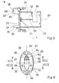
- a lower part shown in FIGS. 1 to 4 or a base 1 of a commodity according to the invention is essentially ring-shaped and a preferred one Embodiment of the invention with a in the front view (Fig. 1) essentially oval or elliptical outer contour.
- the base 1 also has a essential oval central opening 2, the two opposite, one on each side A region 3 arranged areas is bordered by narrow, thin edge strips 4. On its two other areas, each lying on one side of an axis 5, the The central opening 2, on the other hand, is delimited by diametrically opposite segments 6 (FIG. 1), which have cross sections designed in the manner of ellipse sections.
- axes 3, 5 are perpendicular to one another, axis 3 being the largest diameter and axis 5 the smallest diameter of the oval central opening 2 is assigned.
- the rear sides of the segments 6 and the edge strips 4 form one essentially flat mounting surface 7, with the base 1 when mounting on a wall or the like is applied to them.
- the attachment of the base 1 is e.g. with the help of Fastening screws through screw holes 8 formed in the segments 6 be put.
- At least one of the screw holes 8 preferably has something larger diameter than the diameter of the fastening screws. This larger diameter enables the base 1 to be rotated slightly the screwing in of the fastening screws through the screw holes 8 and thus e.g. exactly plumb positioning of the base 1 on the wall or the like. Even then, if the associated wall holes should not be exactly aligned. It is assumed in the exemplary embodiment that the base 1 at vertical standing axis 3 or the like. Is mounted.
- the segments 6 have lugs 9 and 9 on the side facing away from the mounting surface 7 10 on, perpendicular to the plane formed by axes 3 and 5 over the edge strips 4 protrude, and are towards the central opening 2 through mutually parallel, plane Surfaces 11 and 12 limited, which are substantially perpendicular to the mounting surface 7 and run parallel to axis 5.
- the approach 10 is expedient over the whole Cross section of the associated segment 6 extends, while the approach 9, in particular 3 also shows, in an area bordering the associated segment 6 has the same cross section as this, in the rest of the area at least in the direction parallel to axis 5 is narrower than this segment 6.
- 1, 3 and 4 is in the broad part of the approach 9 and on both sides of the Axis 3 a groove 1-4 incorporated, the bottom of which is indicated by dashed lines in Fig. 1 and which in the view from the left or right in Fig. 1 is a substantially U-shaped Cross section has, in Fig. 1 and 4 is open at the top and forward of one triangular web 15 resulting from the oval curved shape of segment 6 is limited.
- 1, 2 and 4 near the free end of the Approach 10 and on both sides of its screw hole 8 each have a recess in the Surface 12 incorporated, which on the one hand forms a groove 16 and on the other hand one leaves a total of T-shaped web 17.
- the contours of the grooves 16 are shown in FIG.
- both grooves 16 are on the one hand like the grooves 14 at the same Side, i.e. 1 open at the top and on the other hand in the side view of left or right in Fig. 1 e.g. U-shaped.
- they are two grooves each 14 and 16 each arranged in mirror image to axis 3.
- the segments 6 and lugs 9, 10 protruding screw holes 8 in the middle sections each have a diameter jump, one shoulder to rest a sunk in the associated approach 9 and 10 respectively Screw head forms.
- the base 1 has e.g. on the axis 3 lying ends two undercuts open to the mounting surface 7 and only shown in FIG. 4 18 on.
- free end faces 19 of the lugs 9 and 10 form one 7 parallel support surface to the mounting surface.
- An upper part 21 of the commodity according to the invention contains according to FIGS. 5 to 8 a shaft section 22 and one for mounting on the base 1 or for fastening of the upper part 21 on the base 1 certain foot section 23.
- the shaft section 22 has in the exemplary embodiment an oval cross section and a central axis 24 and is on one End connected to an end wall 25 of the foot portion 23, which is also an oval, but compared to the shaft section 22 has a larger cross section and an outer Has contour that corresponds essentially to the outer contour of the base 1 and therefore analogous to this one each largest and smallest, running along axes 26, 27 (FIG. 6) Has diameter.
- the end wall 25 with two pairs is on the side facing away from the shaft section 22 of vertically projecting lugs 28, 29 and 30, 31 bordering on their outer contour provided, according to Fig. 6, the approaches 28,29 at one end of the long Diameter and the lugs 30.31 at the other end of the long diameter and on either side of a central plane of the upper part 21 formed by the axis 26 are arranged.
- the approaches 28.29 on the one hand and the approaches 30.31 on the other hand each formed in the same way as a mirror image of this central plane and arranged, as is the case in FIG. 1 for the grooves 14, 16 with respect to the axis 3.
- All four approaches 28 to 31 are parts of an imaginary, on the circumference of the end wall 25 molded oval collar made of a comparatively thin, hollow cylindrical Wall section exists, the outer surface of which is flush with the outer contour of the End wall 25 closes and provided with imaginary cutouts in the circumferential direction which only leaves the four approaches 28 to 31.
- Free end faces 32 of the lugs 28 to 31 form a common support surface running parallel to the end wall 25 (FIG. 5), whose distance from the back of the end wall 25 is essentially the distances of the End faces 19 (Fig. 4) corresponds to the front surfaces of the edge strips 4.
- the lugs 28, 29 are on both sides of the axis 26 formed center plane with such a distance measured parallel to the axis 27 arranged that between them a gap 33 (Fig. 7) is formed, the width of which corresponds to the width of the shoulder 9 (FIG. 1) of the base 1 measured parallel to the axis 5, so that the approach 9 at the correct, coaxial attachment of the foot portion 23 to the Base 1 is received by the gap 33 and then with an outer surface 34 (Fig. 1) outer oval outer surfaces 35 (FIG. 6) of the two lugs 28, 29 continues.
- Fig. 1 outer oval outer surfaces 35
- the projections 38 are on the approaches 28,29 molded and best seen in FIGS. 5 and 6. After that exist the projections 38 from small triangular tongues that extend from the free ends of the Lugs 28, 29 project substantially radially inwards and are designed so that they are in the grooves 14 (Fig. 1.3) of the base 1 fit.
- the projections 39 are middle Formed areas of the approaches 30,31 and best seen in FIGS. 5, 6 and 8. Thereafter, the projections 39 consist of essentially parallel to the axis 27, of the approaches 30.31 radially inwardly projecting webs (Fig.
- FIG. 9 to 11 show a cap 40 of a commodity according to the invention, the a head portion 41 in the form of a flat oval disc and one on the outer Has molded on the edge of the disc, hollow cylindrical shell portion 42.
- the Head section 41 has an oval, centrally located opening 43, the inner cross section essentially the outer cross section of the shaft section 22 of the upper part 21 corresponds, and can be placed with this opening 43 on the shaft portion 22 and then be sliding back and forth on this.
- the jacket section 42 is on the two the smallest ends with radii of curvature, each with an inwardly projecting end Provide undercut 44 with the undercuts 18 (FIG. 4) of the base 1 can cooperate in the manner of snap connection elements.
- the cap 40 with its opening 43 is first placed on the shaft section 42 of the upper part 21 inserted that its jacket section 42 the foot section 23rd is facing.
- the base 1 with schematically indicated fastening screws 48, which are inserted into the screw holes 8, or the like on a wall. attached that it bears with its mounting surface 7 on the wall and the screw heads on the shoulders formed by the jump in diameter of the screw holes 8 (FIG. 3) and so that they come to lie completely within the screw holes 8.
- the assembly takes place of the base 1 in the embodiment so that its axis 3 vertically according to FIG. 1 is arranged and the approach 9 lies above.
- the upper part 21 is now approached with its foot section 23 in front of the wall supporting the base 1 (arrow v in FIGS. 5 and 14), the foot section 23 being held in such a way that the axis 26 (Fig. 6) is arranged substantially vertically, the lugs 28, 29 are at the top and the foot section 23 is arranged overall above the base 1.
- the foot section 23 is now lowered from above onto the base 1 (arrow w in FIGS. 5 and 14), its lugs 30, 31 allowing the lug 9 of the base 1 to pass between them because their distance from one another is sufficiently wider than the lug 9 is.
- the projections 39 FIGS.
- the cap 40 is advanced on the shaft section 22 in the direction of the arrow v (FIG. 14) until it completely absorbs the base 1 and the foot section 23 and with a free end face 45 (FIGS. 10, 14) of the jacket section 42 abuts the wall or the like. That is, it is essentially flush with the mounting surface 7 of the base 1.
- the undercuts 18, 44 (FIGS. 4, 10, 13) form a snap connection, which holds the cap 40 on the base 1 in an axially non-displaceable manner.
- the inner contour of the jacket section 42 of the cap 40 expediently corresponds essentially to that oval outer contour which together form the outer surfaces 34 to 37 of the base 1 and the foot section 23 in the assembled state and which are essentially only due to the spaces between the lugs 28, 30 on the one hand or 29.31 on the other hand is interrupted.
- the jacket section 42 encloses, with little play, in particular that part of the outer contour which is formed by the projection 9 of the base 1 and the two adjacent projections 28, 29 of the foot section 23 (FIG. 14), so that in this assembled state Separation of the first and second connecting elements formed by the grooves 14, 16 and projections 38, 39 is prevented by positive locking.
- the cap 40 Since the cap 40 cannot be moved upwards on the base 1, it is impossible to lift the foot section 23 from the base 1 upwards or against the arrow w (FIGS. 5, 14). In the assembled state, not only the base 1 and the foot section 23 are covered by the cap 40, but the cap 40 also locks the connection made in its front end position. If, on the other hand, a separation of the first and second connecting means is desired, the cap 40 on the shaft section 22 only needs to be brought into a position so far retracted against the arrow v that the base 1 and the foot section 23 are exposed.
- the snap connection elements 18, 44 can be released in a manner known per se by lever action using a suitable tool, which is inserted, for example, into a small recess 46 (FIGS. 10, 11), which for this purpose is located at the free end of the jacket section 42 can be provided in the lower region of the cap 40.
- the height of the cap 40 is appropriately such that it is at least the height of the Socket 1 and the foot section 23 corresponds to completely cover both and in to make the assembled state invisible. This is at the same time a certain protection against unauthorized dismantling, since there are no starting points for a Disassembly are recognizable.
- the undercuts 44 of the cap 40 preferably designed such that they are only under slight pressure and under slight elastic deformation of the jacket section 42 over the end wall 25 of the foot section 23 of the upper part 21 can be pushed. This makes it possible to open the cap 40 to pre-assemble the shaft section 22 until they have the undercuts 44 over the End wall 25 advanced and then essentially captive on the upper part 21 is held.
- the grooves 16 (FIG. 2) such a shape that the stationary web 17th (Fig. 15) is approximately T-shaped, while at the same time the two projections 39 accordingly 8 are designed so that they have a T-shaped space 47 between them Let stand, the contour of FIG. 15 corresponds exactly to the contour of the web 17.
- the grooves 14, 16 and projections 38, 39 are appropriately dimensioned so that they can be put together with little play and in the direction of the central axis 24 (Fig. 5) only a slight axial play occurs.
- the object of use in the exemplary embodiment is as Wall lamp trained.
- the shaft section 22 of the upper part 21 according to FIG. 5 a radial, substantially rectangular recess 49, which according to FIGS. 6 and 13 at least one side from a radially laterally perpendicular to the central axis 24 bounded inside the hollow cylindrical shaft portion 22 intermediate wall 50 which has a screw hole 51.
- a fastening section is inserted into the recess 49 52 of a connecting piece 53, preferably designed as a hollow body (Fig. 13, 14) are used, the outer contour of the fastening section 52 preferably exactly the outer contour of the wall section recessed from the shaft section 22 corresponds so that the outer surfaces of both are flush with each other.
- the fastening section 52 has a side wall 54 with a threaded hole which, when assembled, onto the screw hole 51 the intermediate wall 50 is aligned and the screwing in of a fastening screw 55 allowed.
- the fastening section 52 is connected to an internally hollow shaft 56 which in the assembled state protrudes radially outwards and upwards and with an external thread is provided, on which an internally threaded section can be screwed into one Bottom 57 of a conical or tulip-shaped carrier in the exemplary embodiment 58 is incorporated.
- a part of the protruding through the bottom 57 into the carrier 58 with the External thread provided shaft 56 also serves the purpose of one with a screw on the corresponding internal thread section provided lamp socket 59 in which, in a known manner, a lamp 60, e.g. a conventional light bulb, to be screwed in can.
- the carrier 58 serves to receive e.g. made of glass, essentially hollow cylindrical lampshade 61, which has an annular shape in a lower region Has support shoulder 62, by means of which he on an upper, correspondingly annular Support surface 63 of the carrier 58 can be placed.
- the lower part of the lampshade 61 is tapered by a adjoining the support shoulder 62 trained mounting wall 64 formed.
- the lampshade 61 is assembled by first using its mounting wall 64 is inserted into the upwardly open carrier 58 until its support shoulder 62 is on the support surface 63 rests. Then a screw ring 65 is placed on one from above Screwed external thread section of the lamp holder 59 until it is from the inside against the mounting wall 64 and thereby the support shoulder 62 firmly against the support surface 63 presses. The lamp 60 is then screwed into the socket 59.
- a conventional power network e.g. three electric Lines 66 (Fig. 13) are provided, two of which are known to the lamp holder 59 are connected, while the third line, for example, as a protective conductor connection serves and is attached to the connector 53.
- the lines 66 are through the hollow connector 53 and the hollow interior of the shaft portion 22 of the upper part 21 up to the likewise hollow foot section 23.
- the lines 66 with a usual, only in Fig. 13 indicated luster or Terminal block 68 connected, which is arranged between the individual terminal parts and to these parallel passages 69.
- this terminal block 68 is not anywhere inside the hollow foot section 23 of the upper part 21 or inside also hollow base 1 comes to rest, is a clamp holder according to the invention 70 assigned, which in FIGS. 14 and 15 for better clarity, without the terminal block 68 is shown. This also ensures that the terminal block 68 is not the Assembly of the upper part 21 on the base 1 and / or the electrical insulation hampers or the required clearance and creepage distances to the mounting surface are not met.
- the clamp holder 70 has a center piece 71 and two of the latter Parallel clamping pins 72 protruding from the front. These are at a distance the passages 69 of the used terminal block 68 are arranged corresponding distance and provided with a cross section such that they are from the rear of the terminal block 68 forth with a clamp fit in the passages 69.
- the middle piece 71 is provided with four arms 73, two on each side these arms 73 are arranged at a certain distance from each other.
- the axes the arms 73 form an angle ⁇ (FIG. 17) with the axes of the clamping pins 72, which is preferably slightly less than 90 °.
- the arms 73 are so on Center piece 71 formed so that it is somewhat resilient in the area of attachment points 74 are held.
- the free ends of the arms 73 are designed and closed as support surfaces 75 slightly rounded for this purpose.
- the clamp holder 70 can be clamped in the inner jacket of the shaft section 22 of the upper part 21 by means of the resilient arms 73.
- four flat recesses 77 are machined into an inner wall of the shaft section 22, as shown in FIGS. 15 and 19. These are arranged on opposite sides at intervals which are somewhat smaller than the intervals of the support surfaces 75 of the arms 73 of the clamp holder 70.
- the recesses 77 are arranged close to the rear end of the shaft section 22 or shortly before the point where it merges into the end wall 25. Therefore, the clamp holder 73 can be pushed in the direction of an arrow x (FIGS.
- the assembly of the wall lamp described can preferably essentially like can be done as follows:
- cap 40 First the upper part 21, cap 40, connecting piece 53, support 58, Lampshade 61, terminal block 68 and clamp holder 70 existing assembly completely pre-assembled.
- the cap is first in the manner already described 40 pushed onto the shaft section 22 of the upper part 21.
- the Fastening section 52 of the connecting piece 53 according to FIG. 13 in the upper part 21 inserted and fastened by means of the fastening screw 55.
- Terminal block 68 As far as it will go on the clamping pins 72 of the clamp holder 70 plugged on, whereupon the complete unit is inserted into the shaft section 20 and in this is clamped. Then the ends of the lines 66 with the terminal block 68 connected.
- the lampshade 61 can still be by means of the screw ring 65 mounted and the front opening of the shaft portion 22 with a cap 78 (Fig. 13) which e.g. with a clamp or snap connection is attached.
- the pre-assembled in this way forms a coherent and as Entire transportable unit.
- This can be in the retracted position Cap 40 hung on the site on an already assembled base 1 and then through Advancing the cap 40 can be secured thereon, as explained in detail above has been.
- Cap 40 Before hanging on the base 1 there are only those coming out of the wall and to connect the base 1 protruding lines to the terminal block 68.
- the invention is not restricted to the exemplary embodiment described, which is based on can be modified in many ways.
- the different Provide parts with cross-sections other than oval or elliptical and that from the Grooves 14,16 and the projections 38,39 formed first and second connecting elements have shapes other than those shown and different from each other as shown can be connected.
- the grooves 14, 16 and projections 38, 39 through blind holes and into these matching pins or the elements of a sliding guide be replaced.
- the described embodiment offers the special one Advantage that the foot section 23 when hanging in the base 1 only a distance in Direction of arrow w (Fig. 14) needs to be moved, which is much smaller than that Height of the base corresponds.
- the training of the commodity is only to be understood as an example since the upper part 21 also has other functions and e.g. as Holder for shelves, soap dishes or the like or e.g. overall as a wardrobe or Towel rail could be formed.
- the foot section 23 and the shaft section 22 also have substantially the same outer cross sections and be solid instead of hollow.
- the cap 40 is not absolutely necessary to connect to the base 1 by means of a snap connection, since in many cases also a tight fit is sufficient.
- the central axis 24 in the assembled state is perpendicular to the wall or the like and / or the joining or separating movement must be exactly parallel to the wall or the like.
- insulation blocks 79 (Fig. 13) integrally formed on the back of the end wall 25. These lay in the assembled State of the upper part 21 on the free ends of the screw holes 8 of the base 1 and cover these towards the interior of the foot section 23. This will remove the screw heads electrically isolated from the terminal block 68, so that even when they fall off Terminal holder 70 or no voltage breakdowns or when disconnecting any cable Short circuits can occur.
- the insulation blocks 79 prevent Moisture enters the interior of the upper part 21 through the screw holes 8.
- the parts described can be made of the same, but also different materials consist.
- the Base 1, the upper part 21 and the cap 40 made of plastic, in particular made of plastic injection molded parts, while the connector 53 and the carrier 58 e.g. made of zinc or Aluminum, especially zinc die-cast parts.
- the lampshade 61 can instead of glass also from other materials, e.g. Plastic.
Abstract
Description
Die Erfindung betrifft einen Gebrauchsgegenstand der im Oberbegriff des Anspruchs 1
angegebenen Gattung.The invention relates to a commodity in the preamble of
Gebrauchsgegenstände, insbesondere Beschlag- oder Ausstattungsteile dieser Art sind in
zahlreichen Ausführungsformen bekannt, beispielsweise in Form von Seifenschalen,
Zahnglashaltern, Ablagen, Aschenbechern, Türdrückern, Stoßgriffen, Wandleuchten,
Handtuchhaltern, Briefeinwürfen od. dgl. (DE 25 35 894 A1, EP 0 313 971 A1,
DE 37 36 737 A1, DE 94 20 790 U1). Dabei ist in der Regel der Sockel als ein an der
Wand od. dgl. zu befestigendes Montage- bzw. Unterteil ausgebildet, während das
Oberteil die gewünschte Gebrauchsform besitzt, bei der Montage ganz oder teilweise auf
den Sockel oder einen ausgewählten Abschnitt davon aufgesetzt wird und dadurch nicht
nur dem gewünschten Gebrauchszweck dient, sondern gleichzeitig auch diejenigen
Bereiche des Sockels abdecken soll, in denen die zur Befestigung an einer Wand od. dgl.
bestimmten Befestigungsschrauben, elektrischen Anschlußkabel od. dgl. angeordnet sind.Commodities, in particular fittings or fittings of this type are in
numerous embodiments are known, for example in the form of soap dishes,
Toothed glass holders, shelves, ashtrays, door handles, push handles, wall lights,
Towel holders, letter boxes or the like (DE 25 35 894 A1,
Zur festen Verbindung der beiden Teile weist eines davon eine federnde Zunge mit einem hakenförmigen Ansatz od. dgl. auf, der beim Zusammenbau selbsttätig in eine entsprechende Aufnahme des anderen Teils einrastet und durch eine im Oberteil ausgebildete Öffnung nach außen ragt oder durch ein solche Öffnung hindurch betätigt werden kann. Das Lösen der auf diese Weise hergestellten Verbindung erfolgt dadurch, daß mit der Hand oder einem Werkzeug auf die federnde Zunge eingewirkt und dadurch der Ansatz aus der Aufnahme entfernt wird, so daß danach das Oberteil vom Sockel abgezogen werden kann. Die federnde Zunge dient dabei sowohl der Herstellung der Verbindung als auch der Sicherung der Verbindung beim Gebrauch.For the firm connection of the two parts, one of them has a resilient tongue with one Hook-shaped approach or the like. On the assembly automatically in a corresponding Recording of the other part engages and by a trained in the upper part Opening protrudes outwards or can be operated through such an opening. The release of the connection produced in this way takes place in that with the Hand or a tool acted on the resilient tongue and thereby the approach is removed from the receptacle, so that the upper part is then pulled off the base can be. The resilient tongue serves both to make the connection also securing the connection during use.
Bei der Befestigung von Gebrauchsgegenständen in Form von Halterungen für Stangen
oder Rohre ist es bekannt (DE 90 13 681 U1, DE 43 00 997 A1), die Halterung zur
Vermeidung federnder Zungen aus einem Stück mit dem Sockel herzustellen und nach
dessen Befestigung an der Wand eine Rosettenkappe auf den Sockel aufzuschieben, die
eine Mittelöffnung aufweist, durch die ein mit dem Rohr oder der Stange zu verbindendes
Halterungsteil oder das Rohr bzw. die Stange selbst nach außen ragt. Eine Demontage
eines solchen Gebrauchsgegenstands ist dabei nur durch eine komplette Demontage des
Sockels von der Wand möglich.When attaching everyday items in the form of holders for poles
or pipes it is known (DE 90 13 681 U1,
Bei Gebrauchsgegenständen in Form von Handtuchhaltern, insbesondere Handtuchhaltern
mit mehreren Haltearmen, ist es bekannt (DE 31 05 216 C2), den Sockel und das Oberteil
mit einem quer zu den Schraublöchern angeordneten Durchgang zu versehen, in dem die
Haltearme drehbar gelagert werden. Dadurch kann die Anwendung federnder Zungen
ebenfalls vermieden werden. Allerdings ergibt sich das Problem, daß der Gebrauchsgegenstand
nicht werksseitig vormontiert werden kann, weil die Haltearme erst in den
Durchgang des Sockels eingesetzt werden können, nachdem dieser an der Wand befestigt
und das Oberteil aufgesetzt ist. Daher muß der Gebrauchsgegenstand an der Baustelle
zusammengesetzt werden, was insbesondere dann unerwünscht ist, wenn diese Arbeit
vorzugsweise nur von einem Fachmann durchgeführt werden soll.For articles of daily use in the form of towel racks, in particular towel racks
with several holding arms, it is known (
Der Erfindung liegt die Aufgabe zugrunde, den Gebrauchsgegenstand der eingangs bezeichneten Gattung so auszubilden, daß zur Verbindung des Oberteils mit dem Sockel keine federnden Teile benötigt werden und das Oberteil leicht lösbar und so auf dem Sockel montierbar ist, daß es bei Bedarf mit zusätzlichen Bauelementen zu einer als Ganzes auf den Sockel aufsetzbaren Baugruppe vormontiert werden kann.The invention has for its object the commodity of the beginning designated genus so that to connect the upper part with the base no resilient parts are required and the upper part is easily detachable and so on the Base is mountable that if necessary with additional components to a Whole assembly can be preassembled on the base.
Zur Lösung dieser Aufgabe dienen die kennzeichnenden Merkmale des Anspruchs 1.The characteristic features of
Die Erfindung bringt den Vorteil mit sich, daß nach dem Herstellen der Verbindung zwischen dem Oberteil und dem Sockel nur noch die Kappe in ihre vordere Endstellung vorgeschoben werden braucht, um die Verbindung zu sichern. Die Kappe übernimmt dabei die Funktion einer Sicherung der Verbindung durch Formschluß, so daß weder zur Herstellung der Verbindung noch zu deren Sicherung federnde Zungen benötigt werden. Außerdem kann der von der Kappe frei bleibende Teil des Schaftabschnitts als Halterung bzw. Befestigungselement für an sich beliebige Zusatzelemente, beispielsweise in Form einer Lampenfassung und eines Lampengehäuses dienen.The invention has the advantage that after establishing the connection between the upper part and the base only the cap in its front end position needs to be advanced to secure the connection. The cap takes over the function of securing the connection by positive locking, so that neither Making the connection still needed to secure resilient tongues. In addition, the part of the shaft section that remains free of the cap can serve as a holder or fastening element for any additional elements per se, for example in the form serve a lamp holder and a lamp housing.
Weitere vorteilhafte Merkmale der Erfindung ergeben sich aus den Unteransprüchen.Further advantageous features of the invention emerge from the subclaims.
Die Erfindung wird nachfolgend in Verbindung mit der beiliegenden Zeichnung an einem
bevorzugten Ausführungsbeispiel näher erläutert. Es zeigen:
Ein in Fig. 1 bis 4 gezeigtes Unterteil bzw. ein Sockel 1 eines erfindungsgemäßen Gebrauchsgegenstands
ist im wesentlichen ringförmig ausgebildet und bei einer bevorzugten
Ausführungsform der Erfindung mit einer in der Vorderansicht (Fig. 1) im wesentlichen
ovalen oder elliptischen äußeren Kontur versehen. Der Sockel 1 besitzt eine ebenfalls im
wesentlichen ovale Mittelöffnung 2, die an zwei gegenüberliegenden, auf je einer Seite
einer Achse 3 angeordneten Bereichen durch schmale, dünne Randstreifen 4 eingefaßt ist.
An ihren beiden anderen, auf je einer Seite einer Achse 5 liegenden Bereichen wird die
Mittelöffnung 2 dagegen von diametral gegenüberliegender Segmenten 6 (Fig. 1) begrenzt,
die nach Art von Ellipsenabschnitten ausgebildete Querschnitte aufweisen. Die beiden
Achsen 3,5 stehen im Ausführungsbeispiel senkrecht zueinander, wobei die Achse 3 dem
größten Durchmesser und die Achse 5 dem kleinsten Durchmesser der ovalen Mittelöffnung
2 zugeordnet ist. Die Rückseiten der Segmente 6 und der Randstreifen 4 bilden eine
im wesentlichen ebene Montagefläche 7, mit der Sockel 1 bei der Montage an einer Wand
od. dgl. an diese angelegt wird. Die Befestigung des Sockels 1 erfolgt z.B. mit Hilfe von
Befestigungsschrauben, die durch in den Segmenten 6 ausgebildete Schraublöcher 8
gesteckt werden. Wenigstens eines der Schraublöcher 8 besitzt vorzugsweise einen etwas
größeren Durchmesser, als den Durchmessern der Befestigungsschrauben entspricht.
Dieser größere Durchmesser ermöglicht eine geringfügige Verdrehung des Sockels 1 nach
dem Eindrehen der Befestigungsschrauben durch die Schraublöcher 8 hindurch und damit
eine z.B. exakt lotgerechte Positionierung des Sockels 1 an der Wand od. dgl. selbst dann,
wenn die zugehörigen Wandbohrungen nicht exakt aufeinander ausgerichtet sein sollten.
Dabei wird im Ausführungsbeispiel davon ausgegangen, daß der Sockel 1 bei vertikal
stehender Achse 3 an der Wand od. dgl. montiert wird.A lower part shown in FIGS. 1 to 4 or a
Die Segmente 6 weisen auf der von der Montagefläche 7 abgewandten Seite Ansätze 9 und
10 auf, die senkrecht zu der von den Achsen 3 und 5 gebildeten Ebene über die Randleisten
4 hinausragen, und sind zur Mittelöffnung 2 hin durch zueinander parallele, ebene
Flächen 11 und 12 begrenzt, die im wesentlichen senkrecht zur Montagefläche 7 und
parallel zur Achse 5 verlaufen. Dabei ist der Ansatz 10 zweckmäßig über den ganzen
Querschnitt des zugehörigen Segments 6 erstreckt, während der Ansatz 9, wie insbesondere
Fig. 3 zeigt, in einem an das zugehörige Segment 6 grenzenden Bereich ebenfalls
denselben Querschnitt wie dieses besitzt, im restlichen Bereich dagegen zumindest in der
zur Achse 5 parallelen Richtung schmaler als dieses Segment 6 ist.The
Nach Fig. 1, 3 und 4 ist in den breiten Teil des Ansatzes 9 und auf beiden Seiten der
Achse 3 je eine Nut 1-4 eingearbeitet, deren Boden in Fig. 1 gestrichelt angedeutet ist und
die in der Ansicht von links bzw. rechts in Fig. 1 einen im wesentlichen U-förmigen
Querschnitt besitzt, in Fig. 1 und 4 nach oben offen ist und nach vorn von einem etwa
dreieckförmigen, aus der oval gekrümmten Form des Segements 6 resultierenden Steg 15
begrenzt wird. Außerdem ist gemäß Fig. 1, 2 und 4 in der Nähe des freien Endes des
Ansatzes 10 und auf beiden Seiten seines Schraublochs 8 je eine Ausnehmung in die
Fläche 12 eingearbeitet, die einerseits je eine Nut 16 bildet und andererseits einen
insgesamt T-förmigen Steg 17 stehen läßt. Die Konturen der Nuten 16 sind in Fig. 1
gestrichelt angedeutet, und beide Nuten 16 sind einerseits wie die Nuten 14 zur selben
Seite hin, d.h. in Fig. 1 nach oben hin offen und andererseits in der Seitenansicht von
links oder rechts in Fig. 1 z.B. U-förmig ausgebildet. Außerdem sind die je zwei Nuten
14 bzw. 16 jeweils spiegelbildlich zur Achse 3 angeordnet.1, 3 and 4 is in the broad part of the
Wie insbesondere Fig. 2 und 3 weiter zeigen, weisen die Segmente 6 und Ansätze 9, 10
durchragenden Schraublöcher 8 in mittleren Abschnitten je einen Durchmessersprung auf,
der eine Schulter zur Auflage eines versenkt im zugehörigen Ansatz 9 bzw. 10 angeordneten
Schraubenkopfes bildet. Außerdem weist der Sockel 1 z.B. an den auf der Achse 3
liegenden Enden zwei zur Montagefläche 7 hin offene, nur in Fig. 4 gezeigte Hinterschneidungen
18 auf. Schließlich bilden freie Stirnflächen 19 der Ansätze 9 und 10 eine
zur Montagefläche 7 parallele Stützfläche.As particularly shown in FIGS. 2 and 3 further show, the
Ein Oberteil 21 des erfindungsgemäßen Gebrauchsgegenstands enthält nach Fig. 5 bis 8
einen Schaftabschnitt 22 und einen zum Aufsetzen auf den Sockel 1 bzw. zur Befestigung
des Oberteils 21 am Sockel 1 bestimmten Fußabschnitt 23. Der Schaftabschnitt 22 besitzt
im Ausführungsbeispiel einen ovalen Querschnitt und eine Mittelachse 24 und ist an einem
Ende mit einer Stirnwand 25 des Fußabschnitts 23 verbunden, die ebenfalls einen ovalen,
aber im Vergleich zum Schaftabschnitt 22 größeren Querschnitt aufweist und eine äußere
Kontur besitzt, die im wesentlichen der äußeren Kontur des Sockels 1 entspricht und daher
analog zu dieser je einen größten und kleinsten, längs Achsen 26,27 (Fig. 6) verlaufenden
Durchmesser besitzt.An
Auf der vom Schaftabschnitt 22 abgewandten Seite ist die Stirnwand 25 mit zwei Paaren
von senkrecht abstehenden, an ihre äußere Kontur grenzenden Ansätzen 28,29 bzw. 30,31
versehen, wobei entsprechend Fig. 6 die Ansätze 28,29 am einen Ende des langen
Durchmessers und die Ansätze 30,31 am anderen Ende des langen Durchmessers und
jeweils zu beiden Seiten einer durch die Achse 26 gebildeten Mittelebene des Oberteils 21
angeordnet sind. Die Ansätze 28,29 einerseits und die Ansätze 30,31 andererseits sind
dabei jeweils in derselben Weise spiegelbildlich zu dieser Mittelebene ausgebildet und
angeordnet, wie dies nach Fig. 1 für die Nuten 14, 16 bezüglich der Achse 3 zutrifft. Alle
vier Ansätze 28 bis 31 sind Teile eines gedachten, an den Umfang der Stirnwand 25
angeformten, ovalen Kragens, der aus einem vergleichsweise dünnen, hohlzylindrischen
Wandabschnitt besteht, dessen äußere Mantelfläche bündig mit der äußeren Kontur der
Stirnwand 25 abschließt und der in Umfangsrichtung mit gedachten Ausschnitten versehen
ist, die nur die vier Ansätze 28 bis 31 stehen lassen. Freie Stirnflächen 32 der Ansätze 28
bis 31 bilden eine gemeinsame, parallel zur Stirnwand 25 verlaufende Stützfläche (Fig. 5),
deren Abstand von der Rückseite der Stirnwand 25 im wesentlichen den Abständen der
Stirnflächen 19 (Fig. 4) von den Vorderflächen der Randstreifen 4 entspricht.The
Die Ansätze 28, 29 sind entsprechend Fig. 12 auf beiden Seiten der durch die Achsen 26
gebildeten Mittelebene mit einem solchen parallel zur Achse 27 gemessenen Abstand
angeordnet, daß zwischen ihnen ein Spalt 33 (Fig. 7) gebildet ist, dessen Breite der
parallel zur Achse 5 gemessenen Breite des Ansatzes 9 (Fig. 1) des Sockels 1 entspricht,
so daß der Ansatz 9 beim richtigen, koaxialen Ansetzen des Fußabschnitts 23 an den
Sockel 1 vom Spalt 33 aufgenommen wird und dann mit einer Außenfläche 34 (Fig. 1)
äußere ovale Außenflächen 35 (Fig. 6) der beiden Ansätze 28,29 fortsetzt. Dagegen sind
die beiden Ansätze 30,31 räumlich so am Umfang der Stirnwand 25 angeordnet, daß sie
sich beim richtigen, koaxialen Aufsetzen des Fußabschnitts 23 auf den Sockel 1 an die
Fläche 12 (Fig. 1) anlegen und dabei mit ihren ovalen Außenflächen 36 (Fig. 6) eine
Außenfläche 37 (Fig. 1) des Ansatzes 10 fortsetzen. Dadurch stützen sich die freien
Stirnflächen 19 der Ansätze 9 und 10 des Sockels 1 im montierten Zustand im wesentlichen
an der Unterseite der Stirnwand 25 und die freien Stirnflächen 32 der Ansätze 28 bis
31 im wesentlichen an der Vorderfläche der Randstreifen 4 ab, wie am besten die weiter
unten erläuterten Fig. 13 bis 15 erkennen lassen, wobei die Flächen 34 bis 37 eine
gemeinsame äußere Kontur bilden.According to FIG. 12, the
Zur festen, axialen Befestigung des Oberteils 21 am Sockel 1 dienen am Fußabschnitt 23
angebrachte, hakenartige Zungen oder Vorsprünge 38 und 39. Die Vorsprünge 38 sind an
die Ansätze 28,29 angeformt und am besten aus Fig. 5 und 6 ersichtlich. Danach bestehen
die Vorsprünge 38 aus kleinen, dreieckförmigen Zungen, die von den freien Enden der
Ansätze 28,29 im wesentlichen radial nach innen ragen und so ausgebildet sind, daß sie in
die Nuten 14 (Fig. 1,3) des Sockels 1 passen. Dagegen sind die Vorsprünge 39 mittleren
Bereichen der Ansätze 30,31 angeformt und am besten aus Fig. 5, 6 und 8 ersichtlich.
Danach bestehen die Vorsprünge 39 aus im wesentlichen parallel zur Achse 27 verlaufenden,
von den Ansätzen 30,31 radial nach innen ragenden Stegen (Fig. 6,8), die so
ausgebildet sind, daß sie in die Nuten 16 (Fig. 1,2) des Sockels 1 passen. Außerdem sind
die Vorsprünge 38,39 jeweils spiegelbildlich zur Achse 26 und in der Ansicht nach Fig. 6
so angeordnet, daß sie von oben her in die Nuten 14,16 des nach Fig. 1 angeordneten
Sockels 1 eingesetzt bzw. eingehängt werden können. Dabei bilden die Nuten 14 und 16
jeweils erste Verbindungsmittel und die Vorsprünge 38,39 jeweils zweite Verbindungsmittel,
die mit den ersten Verbindungsmitteln durch einen einfachen Steckvorgang
verbunden werden können. For fixed, axial fastening of the
Fig. 9 bis 11 zeigen eine Kappe 40 eines erfindungsgemäßen Gebrauchsgegenstands, die
einen Kopfabschnitt 41 in Form einer flachen, ovalen Scheibe und einen an den äußeren
Rand der Scheibe angeformten, hohlzylindrischen Mantelabschnitt 42 aufweist. Der
Kopfabschnitt 41 weist eine ovale, zentral gelegene Öffnung 43 auf, deren Innenquerschnitt
im wesentlichen dem Außenquerschnitt des Schaftabschnitts 22 des Oberteils 21
entspricht, und kann mit dieser Öffnung 43 auf den Schaftabschnitt 22 aufgesetzt und dann
gleitend auf diesem hin- und herbewegt werden. Der Mantelabschnitt 42 ist an den beiden
die kleinsten Krümmungsradien aufweisenden Enden mit je einer nach innen ragenden
Hinterschneidung 44 versehen, die mit den Hinterschneidungen 18 (Fig. 4) des Sockels 1
nach Art von Schnappverbindungselementen zusammenwirken können.9 to 11 show a
Fig. 12 bis 15 zeigen den Sockel 1, das Oberteil 21 und die Kappe 40 eines im Ausführungsbeispiel
als Wandleuchte ausgebildeten Gebrauchsgegenstands im zusammengesetzten
Zustand. Die Montage erfolgt dabei z.B. auf folgende Weise:12 to 15 show the
Es wird zunächst gemäß Fig. 13 die Kappe 40 mit ihrer Öffnung 43 so auf den Schaftabschnitt
42 des Oberteils 21 gesteckt, daß ihr Mantelabschnitt 42 dem Fußabschnitt 23
zugewandt ist. Außerdem wird der Sockel 1 mit schematisch angedeuteten Befestigungsschrauben
48, die in die Schraublöcher 8 eingeführt werden, so an einer Wand od. dgl.
befestigt, daß er mit seiner Montagefläche 7 an der Wand anliegt und die Schraubenköpfe
auf den vom Durchmessersprung der Schraublöcher 8 gebildeten Schultern (Fig. 3) und
damit völlig innerhalb der Schraublöcher 8 zu liegen kommen. Dabei erfolgt die Montage
des Sockels 1 im Ausführungsbeispiel so, daß seine Achse 3 entsprechend Fig. 1 vertikal
angeordnet ist und der Ansatz 9 oben liegt.According to FIG. 13, the
Das Oberteil 21 wird nun, wie insbesondere Fig. 13 und 14 zeigen, mit seinem Fußabschnitt
23 voran der den Sockel 1 tragenden Wand angenähert (Pfeil v in Fig. 5
und 14), wobei der Fußabschnitt 23 so gehalten wird, daß die Achse 26 (Fig. 6) im
wesentlichen vertikal angeordnet ist, die Ansätze 28,29 oben liegen und der Fußabschnitt
23 insgesamt oberhalb des Sockels 1 angeordnet ist. Der Fußabschnitt 23 wird nun
von oben her auf den Sockel 1 abgesenkt (Pfeil w in Fig. 5 und 14), wobei seine Ansätze
30,31 den Ansatz 9 des Sockels 1 zwischen sich passieren lassen, weil ihr Abstand
voneinander ausreichend breiter als der Ansatz 9 ist. Beim weiteren Absenken des Fußabschnitts
23 und richtiger Ausrichtung relativ zum Sockel 1 treten dann die an den
Ansätzen 30,31 angebrachten Vorsprünge 39 (Fig. 6,8) in die Nuten 16 (Fig. 1,2) des
Sockels 1 und im wesentlichen gleichzeitig die Vorsprünge 38 (Fig. 5,7) in die Nuten 14
(Fig. 1,3) des Sockels 1 ein. Dadurch wird der Fußabschnitt 23 fest in den Sockel 1
eingehängt und gegen eine Herausnahme in axialer Richtung, d.h. in Richtung der
Mittelachse 24 bzw. entgegen dem Pfeil v (Fig. 5,14) gesichert. Ein Herabfallen des
Fußabschnitts 23 vom Sockel nach unten (Pfeil w in Fig. 5,14) ist nicht möglich, weil die
Vorsprünge 38,39 von den Böden der Nuten 14,16 abgestützt werden. Außerdem wird ein
seitliches Verkippen des Fußabschnitts 23 am Sockel 1 weitgehend dadurch verhindert,
daß die Stirnflächen 19,32 (Fig. 4,5) an der Stirnwand 25 bzw. an den Randstreifen 4
abgestützt sind.13 and 14, the
Abschließend wird die Kappe 40 auf dem Schaftabschnitt 22 in Richtung des Pfeils v
(Fig. 14) vorgeschoben, bis sie den Sockel 1 und den Fußabschnitt 23 vollständig in sich
aufnimmt und mit einer freien Stirnfläche 45 (Fig. 10,14) des Mantelabschnitts 42 an der
Wand od. dgl. anliegt, d.h. mit der Montagefläche 7 des Sockels 1 im wesentlichen
bündig abschließt. In dieser Endstellung der Kappe 40 bilden die Hinterschneidungen
18,44 (Fig. 4,10,13) eine Schnappverbindung, die Kappe 40 axial unverschiebbar auf dem
Sockel 1 festhält.Finally, the
Die innere Kontur des Mantelabschnitts 42 der Kappe 40 entspricht zweckmäßig im
wesentlichen derjenigen ovalen äußeren Kontur, die Außenflächen 34 bis 37 des Sockels 1
und des Fußabschnitts 23 im montierten Zustand gemeinsam bilden und die im wesentlichen
nur durch die Zwischenräume zwischen den Ansätzen 28,30 einerseits bzw. 29,31
andererseits unterbrochen ist. Dadurch umschließt der Mantelabschnitt 42 im montierten
Zustand mit wenig Spiel insbesondere denjenigen Teil der äußeren Kontur, der vom
Ansatz 9 des Sockels 1 und den beiden benachbarten Ansätzen 28,29 des Fußabschnitts 23
gebildet ist (Fig. 14), so daß in diesem Montagezustand ein Trennen der ersten und
zweiten, von den Nuten 14,16 und Vorsprüngen 38,39 gebildeten Verbindungselementen
durch Formschluß verhindert wird. Da die Kappe 40 auf dem Sockel 1 nicht nach oben
verschoben werden kann, ist ein Abheben des Fußabschnitts 23 vom Sockel 1 nach oben
bzw. entgegen dem Pfeil w (Fig. 5,14) unmöglich. Im montierten Zustand werden somit
nicht nur der Sockel 1 und der Fußabschnitt 23 von der Kappe 40 abgedeckt, sondern die
Kappe 40 verriegelt in ihrer vorderen Endstellung zugleich auch die hergestellte Verbindung.
Ist dagegen ein Trennen der ersten und zweiten Verbindungsmittel erwünscht,
braucht die Kappe 40 auf dem Schaftabschnitt 22 entgegen dem Pfeil v nur in eine so weit
zurückgezogene Lage gebracht werden, daß der Sockel 1 und der Fußabschnitt 23 frei
liegen. Zu diesem Zweck können die Schnappverbindungselemente 18,44 in an sich
bekannter Weise durch Hebelwirkung mittels eines geeigneten Werkzeugs gelöst werden,
das z.B. in eine kleine Ausnehmung 46 (Fig. 10,11) eingeführt wird, die zu diesem
Zweck am freien Ende des Mantelabschnitts 42 im unteren Bereich der Kappe 40
vorgesehen sein kann.The inner contour of the
Die Höhe der Kappe 40 ist zweckmäßig so bemessen, daß sie wenigstens der Höhe des
Sockels 1 und des Fußabschnitts 23 entspricht, um beide vollständig abzudecken und im
montierten Zustand unsichtbar zu machen. Damit ist gleichzeitig ein gewisser Schutz
gegen unbefugte Demontage gegeben, da von außen keinerlei Ansatzpunkte für eine
Demontage erkennbar sind. Außerdem werden die Hinterschneidungen 44 der Kappe 40
vorzugsweise derart ausgebildet, daß sie nur mit leichtem Druck und unter geringfügiger
elastischer Verformung des Mantelabschnitts 42 über die Stirnwand 25 des Fußabschnitts
23 des Oberteils 21 geschoben werden können. Dadurch ist es möglich, die Kappe 40 auf
dem Schaftabschnitt 22 vorzumontieren, bis sie mit den Hinterschneidungen 44 über die
Stirnwand 25 vorgeschoben und dann im wesentlichen unverlierbar auf dem Oberteil 21
gehalten ist.The height of the
Zur weiteren Erhöhung der Stabilität der beschriebenen Verbindung ist es zweckmäßig,
den Nuten 16 (Fig. 2) eine solche Form zu geben, daß der stehenbleibende Steg 17
(Fig. 15) etwa T-förmig ist, während gleichzeitig die beiden Vorsprünge 39 entsprechend
Fig. 8 so ausgebildet werden, daß sie zwischen sich einen T-förmigen Zwischenraum 47
stehen lassen, dessen Kontur gemäß Fig. 15 genau der Kontur des Stegs 17 entspricht.
Außerdem werden die Nuten 14, 16 und Vorsprünge 38, 39 zweckmäßig so dimensioniert,
daß sie mit geringem Spiel zusammengesteckt werden können und in Richtung der Mittelachse
24 (Fig. 5) nur ein geringes Axialspiel auftritt.To further increase the stability of the connection described, it is advisable
to give the grooves 16 (FIG. 2) such a shape that the stationary web 17th
(Fig. 15) is approximately T-shaped, while at the same time the two
Wie Fig. 12 bis 15 weiter zeigen, ist der Gebrauchsgegenstand im Ausführungsbeispiel als
Wandleuchte ausgebildet. Hierzu weist der Schaftabschnitt 22 des Oberteils 21 nach Fig. 5
eine radiale, im wesentlichen rechteckige Aussparung 49 auf, die nach Fig. 6 und 13 auf
wenigstens einer Seite von einer senkrecht zur Mittelachse 24 verlaufenden, radial nach
innen in den hohlzylindrischen Schaftabschnitt 22 ragenden Zwischenwand 50 begrenzt
wird, die ein Schraubloch 51 aufweist. In die Aussparung 49 wird ein Befestigungsabschnitt
52 eines vorzugsweise als Hohlkörper ausgebildeten Verbindungsstücks 53
(Fig. 13,14) eingesetzt, wobei die äußere Kontur des Befestigungsabschnitts 52 vorzugsweise
genau der äußeren Kontur des aus dem Schaftabschnitt 22 ausgesparten Wandabschnitts
entspricht, so daß die Außenflächen beider bündig miteinander abschließen. Zu
seiner Befestigung am Schaftabschnitt 22 weist der Befestigungsabschnitt 52 eine Seitenwand
54 mit einem Gewindeloch auf, das im montierten Zustand auf das Schraubloch 51
der Zwischenwand 50 ausgerichtet ist und das Eindrehen einer Befestigungsschraube 55
erlaubt.As further shown in FIGS. 12 to 15, the object of use in the exemplary embodiment is as
Wall lamp trained. For this purpose, the
Der Befestigungsabschnitt 52 ist mit einem innen hohlen Schaft 56 verbunden, der im
montierten Zustand radial nach außen und oben ragt und mit einem Außengewinde
versehen ist, auf das ein Innengewindeabschnitt aufgedreht werden kann, der in einen
Boden 57 eines im Ausführungsbeispiel konus- bzw. tulpenförmig ausgebildeten Trägers
58 eingearbeitet ist. Ein durch den Boden 57 in den Träger 58 ragendes Teil des mit dem
Außengewinde versehenen Schafts 56 dient gleichzeitig dem Zweck, eine mit einem
entsprechenden Innengewindeabschnitt versehene Lampenfassung 59 aufzuschrauben, in
die in bekannter Weise eine Lampe 60, z.B. eine übliche Glühlampe, eingedreht werden
kann.The
Der Träger 58 dient zur Aufnahme eines z.B. aus Glas bestehenden, im wesentlichen
hohlzylindrischen Lampenschirms 61, der in einem unteren Bereich eine kreisringförmige
Stützschulter 62 aufweist, mittels derer er auf eine obere, entsprechend kreisringförmige
Stützfläche 63 des Trägers 58 aufgelegt werden kann. Der untere Bereich des Lampenschirms
61 wird von einer an die Stützschulter 62 anschließenden, konisch verjüngt
ausgebildeten Montagewand 64 gebildet.The
Die Montage des Lampenschirms 61 erfolgt dadurch, daß er zunächst mit seiner Montagewand
64 in den nach oben offenen Träger 58 gesteckt wird, bis seine Stützschulter 62 auf
der Stützfläche 63 aufliegt. Anschließend wird von oben her ein Schraubring 65 auf einen
Außengewindeabschnitt der Lampenfassung 59 aufgeschraubt, bis dieser sich von innen
gegen die Montagewand 64 legt und dadurch die Stützschulter 62 fest gegen die Stützfläche
63 drückt. Anschließend wird die Lampe 60 in die Fassung 59 eingedreht.The
Zum Anschluß der Lampe 60 an ein übliches Stromnetz sind z.B. drei elektrische
Leitungen 66 (Fig. 13) vorgesehen, von denen zwei in bekannter Weise mit der Lampenfassung
59 verbunden sind, während die dritte Leitung beispielsweise als Schutzleiteranschluß
dient und am Verbindungsstück 53 befestigt wird. Die Leitungen 66 werden
durch das hohle Verbindungsstück 53 und den hohlen Innenraum des Schaftabschnitts 22
des Oberteils 21 bis in dessen ebenfalls hohlen Fußabschnitt 23 verlegt. Zur Vereinfachung
ihrer Verbindung mit den aus der Wand od. dgl. kommenden Stromleitungen
werden die Leitungen 66 mit einer üblichen, nur in Fig. 13 angedeuteten Lüster- bzw.
Reihenklemme 68 verbunden, die zwischen den einzelnen Klemmenteilen angeordnete und
zu diesen parallele Durchgänge 69 aufweist. Damit diese Reihenklemme 68 nicht irgendwo
innerhalb des hohlen Fußabschnitts 23 des Oberteils 21 bzw. innerhalb des innen
ebenfalls hohlen Sockels 1 zu liegen kommt, ist ihr erfindungsgemäß ein Klemmenhalter
70 zugeordnet, der in Fig. 14 und 15 der besseren Klarheit wegen ohne die Reihenklemme
68 dargestellt ist. Dadurch ist auch sichergestellt, daß die Reihenklemme 68 nicht die
Montage des Oberteils 21 am Sockel 1 und/oder die elektrische Isolierung behindert oder
die geforderten Luft- und Kriechstrecken zur Befestigungsfläche unterschritten werden.For connecting the
Der Klemmenhalter 70 weist nach Fig. 16 bis 18 ein Mittelstück 71 und zwei von dessen
Vorderseite wegragende, parallele Klemmstifte 72 auf. Diese sind in einem dem Abstand
der Durchgänge 69 der verwendeten Reihenklemme 68 entsprechenden Abstand angeordnet
und mit einem solchen Querschnitt versehen, daß sie von der Rückseite der Reihenklemme
68 her mit Klemmsitz in die Durchgänge 69 eingesetzt werden können. An den
Seiten ist das Mittelstück 71 mit vier Armen 73 versehen, wobei an jeder Seite zwei von
diesen Armen 73 mit einem gewissen Abstand voneinander angeordnet sind. Die Achsen
der Arme 73 schließen mit den Achsen der Klemmstifte 72 einen Winkel α (Fig. 17) ein,
der vorzugsweise etwas kleiner als 90° ist. Außerdem sind die Arme 73 so an das
Mittelstück 71 angeformt, daß sie im Bereich von Befestigungsstellen 74 etwas federnd
gehalten sind. Die freien Enden der Arme 73 sind als Stützflächen 75 ausgebildet und zu
diesem Zweck leicht gerundet. 16 to 18, the
Der Klemmenhalter 70 kann gemäß Fig. 15 mittels der federnden Arme 73 im Innenmantel
des Schaftabschnitts 22 des Oberteils 21 festgeklemmt werden. Dazu sind in eine
Innenwand des Schaftabschnitts 22, wie Fig. 15 und 19 zeigen, vier flache Ausnehmungen
77 eingearbeitet. Diese sind auf gegenüberliegenden Seiten in Abständen angeordnet, die
etwas kleiner als die Abstände der Stützflächen 75 der Arme 73 des Klemmenhalters 70
sind. Außerdem sind die Ausnehmungen 77 dicht am Hinterende des Schaftabschnitts 22
bzw. kurz vor der Stelle angeordnet, wo dieser in die Stirnwand 25 übergeht. Daher kann
der Klemmenhalter 73 in Richtung eines Pfeils x (Fig. 15 und 17) so von der Rückseite
des Schaftabschnitts 22 her in diesen eingeschoben werden, bis seine Arme 73, die dabei
leicht zusammengedrückt werden, federnd in die Ausnehmungen 77 einrasten und sich
dann mit ihren Stützflächen 75 an den Böden der Ausnehmungen 77 abstützen. Im
eingerasteten Zustand werden die federnd angebrachten Arme 73 bei einem Versuch, den
Klemmenhalter 77 in Richtung der Mittelachse 24 (Fig. 5) bzw. entgegen dem Pfeil x
(Fig. 15,17) zum Fußabschnitt 23 hin aus dem Schaftabschnitt 22 herauszuziehen, unter
Vergrößerung des Winkels α (Fig. 17) weiter aufgespreizt, da hierdurch ihre Stützflächen
75 gegen die seitlichen Begrenzungswände der Ausnehmungen 77 gezogen werden.
Dadurch bewirkt die Federkraft der Arme 73 eine Verstärkung der Klemm- bzw. Rastwirkung
und damit eine Vergrößerung des Widerstands gegen ein ungewünschtes Herausziehen
des Klemmenhalters 70 aus dem Schaftabschnitt 22.15, the
Die Montage der beschriebenen Wandleuchte kann vorzugsweise im wesentlichen wie folgt vorgenommen werden:The assembly of the wall lamp described can preferably essentially like can be done as follows:
Es wird zunächst die aus Oberteil 21, Kappe 40, Verbindungsstück 53, Träger 58,
Lampenschirm 61, Reihenklemme 68 und Klemmenhalter 70 bestehende Baugruppe
komplett vormontiert. Dazu wird zunächst in der bereits beschriebenen Weise die Kappe
40 auf den Schaftabschnitt 22 des Oberteils 21 geschoben. Anschließend wird der
Befestigungsabschnitt 52 des Verbindungsstücks 53 entsprechend Fig. 13 in das Oberteil
21 eingesetzt und mittels der Befestigungsschraube 55 befestigt. Danach wird der Träger
58 auf den Schaft 56 des Verbindungsstücks 53 und dann die Lampenfassung 59 auf den
Schaft 56 aufgeschraubt, wobei die mit ihr verbundenen Leitungen 66 durch den Schaft 56
und den Schaftabschnitt 22 bis zum Fußabschnitt 23 gezogen werden. Es wird nun die
Reihenklemme 68 bis zum Anschlag auf die Klemmstifte 72 des Klemmenhalters 70
aufgesteckt, worauf die komplette Einheit in den Schaftabschnitt 20 gesteckt und in diesem
festgeklemmt wird. Danach werden dann die Enden der Leitungen 66 mit der Reihenklemme
68 verbunden. Außerdem kann noch der Lampenschirm 61 mittels des Schraubrings
65 montiert und die vordere Öffnung des Schaftabschnitts 22 mit einer Abdeckkappe
78 (Fig. 13) verschlossen werden, die z.B. mit einer Klemm- oder Schnappverbindung
befestigt wird.First the
Die auf diese Weise vormontierte Baugruppe bildet eine zusammenhängende und als
Ganzes transportierbare Einheit. Diese kann bei in zurückgezogener Stellung befindlicher
Kappe 40 an der Baustelle auf einen bereits montierten Sockel 1 gehängt und dann durch
Vorschieben der Kappe 40 auf diesem gesichert werden, wie oben ausführlich erläutert
wurde. Vor der Aufhängung am Sockel 1 sind lediglich noch die aus der Wand kommenden
und den Sockel 1 durchragenden Leitungen an die Reihenklemme 68 anzuschließen.The pre-assembled in this way forms a coherent and as
Entire transportable unit. This can be in the retracted
Die Erfindung ist nicht auf das beschriebene Ausführungsbeispiel beschränkt, das auf
vielfache Weise abgewandelt werden kann. Insbesondere ist klar, daß die verschiedenen
Teile mit anderen als ovalen bzw. elliptischen Querschnitten versehen und die aus den
Nuten 14,16 und den Vorsprüngen 38,39 gebildeten ersten und zweiten Verbindungselemente
andere als die dargestellten Formen besitzen und anders als dargestellt miteinander
verbunden werden können. Beispielsweise können die Nuten 14, 16 und Vorsprünge
38, 39 durch Sacklöcher und in diese passende Stifte oder die Elemente einer Schiebeführung
ersetzt werden. Die beschriebene Ausführungsform bietet dabei den besonderen
Vorteil, daß der Fußabschnitt 23 beim Einhängen in den Sockel 1 nur um eine Strecke in
Richtung des Pfeils w (Fig. 14) bewegt werden braucht, die wesentlich kleiner ist, als der
Höhe des Sockels entspricht. Außerdem ist die Ausbildung des Gebrauchsgegenstands nur
als Beispiel zu verstehen, da das Oberteil 21 auch andere Funktionen haben und z.B. als
Halter für Ablagen, Seifenschalen od. dgl. oder z.B. insgesamt als Garderobe- oder
Handtuchstange ausgebildet sein könnte. Je nach Funktion könnten der Fußabschnitt 23
und der Schaftabschnitt 22 auch im wesentlichen gleiche Außenquerschnitte haben und
massiv statt hohl ausgebildet sein. Weiter ist nicht zwingend erforderlich, die Kappe 40
mittels einer Schnappverbindung mit dem Sockel 1 zu verbinden, da in vielen Fällen auch
ein fester Klemmsitz ausreichend ist. Weiter ist nicht erforderlich, daß die Mittelachse 24
im montierten Zustand senkrecht zur Wand oder dgl. steht und/oder die Füge- bzw. Trennungsbewegung
genau parallel zur Wand oder dgl. erfolgen muß. Nach einer besonders
bevorzugten Ausführungsform sind außerdem senkrecht abstehende Isolierungsklötze 79
(Fig. 13) an die Rückseite der Stirnwand 25 angeformt. Diese legen sich im montierten
Zustand des Oberteils 21 auf die freien Enden der Schraublöcher 8 des Sockels 1 auf und
decken diese zum Innenraum des Fußabschnitts 23 hin ab. Dadurch werden die Schraubenköpfe
elektrisch gegen die Reihenklemme 68 isoliert, so daß auch bei deren Abfallen vom
Klemmenhalter 70 oder beim Lösen irgendeines Kabels keine Spannungsdurchschläge oder
Kurzschlüsse auftreten können. Außerdem verhindern die Isolierungsklötze 79, daß
Feuchtigkeit durch die Schraublöcher 8 in den Innenraum des Oberteils 21 gelangt.
Schließlich versteht sich, daß die verschiedenen Teile des Gebrauchsgegenstands auch in
anderen als in den beschriebenen und in der Zeichnung dargestellten Kombinationen
verwendet werden können.The invention is not restricted to the exemplary embodiment described, which is based on
can be modified in many ways. In particular, it is clear that the different
Provide parts with cross-sections other than oval or elliptical and that from the
Die beschriebenen Teile können aus gleichen, aber auch unterschiedlichen Materialien
bestehen. Bei einer besonders bevorzugten Ausführungsform der Erfindung bestehen der
Sockel 1, das Oberteil 21 und die Kappe 40 aus Kunststoff, insbesondere aus Kunststoff-Spritzgußteilen,
während das Verbindungsstück 53 und der Träger 58 z.B. aus Zink oder
Aluminium, insbesondere Zink-Druckgußteilen bestehen. Der Lampenschirm 61 kann
anstatt aus Glas auch aus anderen Materialien, z.B. Kunststoff, bestehen.The parts described can be made of the same, but also different materials
consist. In a particularly preferred embodiment of the invention, the
Claims (14)
Applications Claiming Priority (2)
| Application Number | Priority Date | Filing Date | Title |
|---|---|---|---|
| DE29803781U DE29803781U1 (en) | 1998-03-05 | 1998-03-05 | Commodity, in particular hardware or fittings |
| DE29803781U | 1998-03-05 |
Publications (2)
| Publication Number | Publication Date |
|---|---|
| EP0956803A2 true EP0956803A2 (en) | 1999-11-17 |
| EP0956803A3 EP0956803A3 (en) | 2001-04-11 |
Family
ID=8053559
Family Applications (1)
| Application Number | Title | Priority Date | Filing Date |
|---|---|---|---|
| EP99104343A Withdrawn EP0956803A3 (en) | 1998-03-05 | 1999-03-04 | Application object, particularly mountings- or equipment part |
Country Status (2)
| Country | Link |
|---|---|
| EP (1) | EP0956803A3 (en) |
| DE (1) | DE29803781U1 (en) |
Citations (10)
| Publication number | Priority date | Publication date | Assignee | Title |
|---|---|---|---|---|
| DE2535894A1 (en) * | 1975-08-12 | 1977-02-17 | Rudolf Wilke | Easily cleaned bathroom soap holder - made in two separable parts so that cover can be easily removed while base remains clean |
| DE3105216A1 (en) * | 1981-02-13 | 1982-09-09 | HEWI Heinrich Wilke GmbH, 3548 Arolsen | Towel holder having two holding arms arranged one above the other |
| EP0313971A1 (en) * | 1987-10-30 | 1989-05-03 | Hewi Heinrich Wilke Gmbh | Fastening device for outfit pieces, especially for racks |
| DE3736737A1 (en) * | 1987-10-30 | 1989-05-11 | Wilke Heinrich Hewi Gmbh | FILE |
| DE9013681U1 (en) * | 1990-09-27 | 1991-02-14 | Hewi Heinrich Wilke Gmbh, 3548 Arolsen, De | |
| DE4300997A1 (en) * | 1993-01-15 | 1994-07-21 | Wilke Heinrich Hewi Gmbh | Device for fastening a plate-shaped component to a wall or the like |
| DE9420790U1 (en) * | 1994-12-28 | 1996-05-02 | Wilke Heinrich Hewi Gmbh | lamp |
| DE19510941A1 (en) * | 1995-03-25 | 1996-09-26 | Grohe Kg Hans | Wall holder for sanitary fittings |
| DE19510085A1 (en) * | 1995-03-20 | 1996-10-02 | Hansa Metallwerke Ag | holder |
| DE29618274U1 (en) * | 1996-10-22 | 1997-02-13 | Sks Metaplast Scheffer Klute | Wall bracket for sanitary ware |
Family Cites Families (5)
| Publication number | Priority date | Publication date | Assignee | Title |
|---|---|---|---|---|
| DE7004313U (en) * | 1970-02-07 | 1970-06-04 | Reininghaus & Co | FIXING FITTINGS FOR LIGHTS. |
| DE2320873C3 (en) * | 1973-04-25 | 1978-07-13 | Glashuette Limburg Bruno Und Heinrich Gantenbrink, 6250 Limburg | Fixing device for wall lights |
| AU5200386A (en) * | 1984-11-27 | 1986-06-18 | Kudos Lighting Ltd. | Ceiling roses |
| GB2232076A (en) * | 1989-04-21 | 1990-12-05 | Jam Boo Lin | Bookrest |
| DE4307776C1 (en) * | 1993-03-12 | 1994-07-14 | Keune & Co Kg P | Wall-mounted sanitary fitting |
-
1998
- 1998-03-05 DE DE29803781U patent/DE29803781U1/en not_active Expired - Lifetime
-
1999
- 1999-03-04 EP EP99104343A patent/EP0956803A3/en not_active Withdrawn
Patent Citations (10)
| Publication number | Priority date | Publication date | Assignee | Title |
|---|---|---|---|---|
| DE2535894A1 (en) * | 1975-08-12 | 1977-02-17 | Rudolf Wilke | Easily cleaned bathroom soap holder - made in two separable parts so that cover can be easily removed while base remains clean |
| DE3105216A1 (en) * | 1981-02-13 | 1982-09-09 | HEWI Heinrich Wilke GmbH, 3548 Arolsen | Towel holder having two holding arms arranged one above the other |
| EP0313971A1 (en) * | 1987-10-30 | 1989-05-03 | Hewi Heinrich Wilke Gmbh | Fastening device for outfit pieces, especially for racks |
| DE3736737A1 (en) * | 1987-10-30 | 1989-05-11 | Wilke Heinrich Hewi Gmbh | FILE |
| DE9013681U1 (en) * | 1990-09-27 | 1991-02-14 | Hewi Heinrich Wilke Gmbh, 3548 Arolsen, De | |
| DE4300997A1 (en) * | 1993-01-15 | 1994-07-21 | Wilke Heinrich Hewi Gmbh | Device for fastening a plate-shaped component to a wall or the like |
| DE9420790U1 (en) * | 1994-12-28 | 1996-05-02 | Wilke Heinrich Hewi Gmbh | lamp |
| DE19510085A1 (en) * | 1995-03-20 | 1996-10-02 | Hansa Metallwerke Ag | holder |
| DE19510941A1 (en) * | 1995-03-25 | 1996-09-26 | Grohe Kg Hans | Wall holder for sanitary fittings |
| DE29618274U1 (en) * | 1996-10-22 | 1997-02-13 | Sks Metaplast Scheffer Klute | Wall bracket for sanitary ware |
Also Published As
| Publication number | Publication date |
|---|---|
| DE29803781U1 (en) | 1999-07-08 |
| EP0956803A3 (en) | 2001-04-11 |
Similar Documents
| Publication | Publication Date | Title |
|---|---|---|
| DE1900078A1 (en) | Fastening device | |
| DE3843095A1 (en) | FASTENING DEVICE FOR FAIRING | |
| EP1994614B1 (en) | Frame construction for a switchgear cabinet, switchgear cabinet and construction kit for the switchgear cabinet | |
| DE4124066C2 (en) | Electric lighting system | |
| WO2008025752A1 (en) | Connecting device for lamps | |
| DE202011005654U1 (en) | Fastening element for connecting two components | |
| EP0874423B1 (en) | Fixing device for bus bar | |
| DE19540111B4 (en) | Electronics and instrumentation housing | |
| AT408162B (en) | ADAPTER, BUSBAR AND COUPLING DEVICE | |
| EP1193822B1 (en) | Bus bar support | |
| EP0688919A1 (en) | Construction assembly, in particular for buses | |
| DE3817133C2 (en) | ||
| EP1586816A2 (en) | Ceiling lighting fixture | |
| EP0956803A2 (en) | Application object, particularly mountings- or equipment part | |
| EP0773615A1 (en) | Switchgear cabinet for electrical installations | |
| EP3091276B1 (en) | Lighting fixture to be mounted in a support, in particular in a relevant guide-holder | |
| DE3001990A1 (en) | LAMP HOLDER | |
| DE1905735A1 (en) | Suspended ceiling construction | |
| AT520997A1 (en) | mounting bracket | |
| EP0802586A2 (en) | Sockel, especially for rod-shaped fluorescent tubes | |
| DE102008017108B4 (en) | Electrical installation device and system of juxtaposed electrical installation equipment | |
| AT409904B (en) | Current rail and coupling device | |
| EP0733746A2 (en) | Support | |
| DE3008307A1 (en) | Profiled section fixing device - comprises clips with pairs of arms engaging with different sections and spread apart | |
| EP1351559B1 (en) | Fastening system for electronic and/or mechanical components of a lighting device |
Legal Events
| Date | Code | Title | Description |
|---|---|---|---|
| PUAI | Public reference made under article 153(3) epc to a published international application that has entered the european phase |
Free format text: ORIGINAL CODE: 0009012 |
|
| AK | Designated contracting states |
Kind code of ref document: A2 Designated state(s): AT BE CH DE DK ES FR GB IT LI LU NL SE |
|
| AX | Request for extension of the european patent |
Free format text: AL;LT;LV;MK;RO;SI |
|
| PUAL | Search report despatched |
Free format text: ORIGINAL CODE: 0009013 |
|
| AK | Designated contracting states |
Kind code of ref document: A3 Designated state(s): AT BE CH CY DE DK ES FI FR GB GR IE IT LI LU MC NL PT SE |
|
| AX | Request for extension of the european patent |
Free format text: AL;LT;LV;MK;RO;SI |
|
| RIC1 | Information provided on ipc code assigned before grant |
Free format text: 7A 47K 10/10 A, 7A 47K 1/09 B, 7A 47K 5/00 B, 7F 21S 13/02 B, 7F 21S 1/02 B, 7F 21V 21/02 B, 7F 16B 9/02 B |
|
| AKX | Designation fees paid |
Free format text: AT BE CH DE DK ES FR GB IT LI LU NL SE |
|
| STAA | Information on the status of an ep patent application or granted ep patent |
Free format text: STATUS: THE APPLICATION IS DEEMED TO BE WITHDRAWN |
|
| 18D | Application deemed to be withdrawn |
Effective date: 20011012 |