EP0956709B1 - Virtual studio position sensing system - Google Patents
Virtual studio position sensing system Download PDFInfo
- Publication number
- EP0956709B1 EP0956709B1 EP98901393A EP98901393A EP0956709B1 EP 0956709 B1 EP0956709 B1 EP 0956709B1 EP 98901393 A EP98901393 A EP 98901393A EP 98901393 A EP98901393 A EP 98901393A EP 0956709 B1 EP0956709 B1 EP 0956709B1
- Authority
- EP
- European Patent Office
- Prior art keywords
- camera
- studio
- led
- positioning system
- virtual studio
- Prior art date
- Legal status (The legal status is an assumption and is not a legal conclusion. Google has not performed a legal analysis and makes no representation as to the accuracy of the status listed.)
- Expired - Lifetime
Links
- 238000001514 detection method Methods 0.000 claims description 28
- 230000005855 radiation Effects 0.000 claims description 15
- 238000012545 processing Methods 0.000 claims description 10
- 238000004364 calculation method Methods 0.000 claims description 8
- 230000001360 synchronised effect Effects 0.000 claims description 8
- 238000001228 spectrum Methods 0.000 claims description 5
- 230000003068 static effect Effects 0.000 claims description 5
- 230000002123 temporal effect Effects 0.000 claims description 4
- 230000009466 transformation Effects 0.000 claims description 4
- 230000003595 spectral effect Effects 0.000 claims description 3
- 238000000295 emission spectrum Methods 0.000 claims description 2
- 238000003384 imaging method Methods 0.000 claims 1
- 238000004091 panning Methods 0.000 description 3
- 238000003909 pattern recognition Methods 0.000 description 3
- 238000005259 measurement Methods 0.000 description 2
- 238000009877 rendering Methods 0.000 description 2
- XUIMIQQOPSSXEZ-UHFFFAOYSA-N Silicon Chemical compound [Si] XUIMIQQOPSSXEZ-UHFFFAOYSA-N 0.000 description 1
- 238000010586 diagram Methods 0.000 description 1
- 230000000694 effects Effects 0.000 description 1
- 238000005286 illumination Methods 0.000 description 1
- 238000000034 method Methods 0.000 description 1
- 238000012544 monitoring process Methods 0.000 description 1
- 230000003287 optical effect Effects 0.000 description 1
- 238000012552 review Methods 0.000 description 1
- 238000005096 rolling process Methods 0.000 description 1
- 229920006395 saturated elastomer Polymers 0.000 description 1
- 229910052710 silicon Inorganic materials 0.000 description 1
- 239000010703 silicon Substances 0.000 description 1
- 239000007787 solid Substances 0.000 description 1
- 238000002604 ultrasonography Methods 0.000 description 1
Images



Classifications
-
- H—ELECTRICITY
- H04—ELECTRIC COMMUNICATION TECHNIQUE
- H04N—PICTORIAL COMMUNICATION, e.g. TELEVISION
- H04N5/00—Details of television systems
- H04N5/222—Studio circuitry; Studio devices; Studio equipment
- H04N5/262—Studio circuits, e.g. for mixing, switching-over, change of character of image, other special effects ; Cameras specially adapted for the electronic generation of special effects
- H04N5/272—Means for inserting a foreground image in a background image, i.e. inlay, outlay
-
- H—ELECTRICITY
- H04—ELECTRIC COMMUNICATION TECHNIQUE
- H04N—PICTORIAL COMMUNICATION, e.g. TELEVISION
- H04N5/00—Details of television systems
- H04N5/222—Studio circuitry; Studio devices; Studio equipment
-
- H—ELECTRICITY
- H04—ELECTRIC COMMUNICATION TECHNIQUE
- H04N—PICTORIAL COMMUNICATION, e.g. TELEVISION
- H04N9/00—Details of colour television systems
- H04N9/64—Circuits for processing colour signals
- H04N9/74—Circuits for processing colour signals for obtaining special effects
- H04N9/75—Chroma key
Definitions
- the present invention relates to a virtual studio and in particular to a position sensing system for such a studio.
- the position of the camera is calculable by using a coded pattern on the chroma-key background. This enables the position of the camera, as well as its orientation and the lens zoom, to be continuously calculated and thereby the perspective of the virtual 3D set can be adjusted correctly to suit the camera position.
- the camera is provided with an independent means for indicating the position of the camera which means are used either alone or in conjunction with the coded pattern and the pattern recognition apparatus to ensure correct interpretation of the position of the camera.
- WO-A-96-32697 discloses a hand held camera tracking system comprising a 3-D rendering system coupled to a magnetic tracker system which provides position and orientation information of the hand held camera.
- EBU Technical Review No. 268, 1 June 1996, pp. 2-6 discloses the use of distance measurement by, for example, a laser ultrasound or infrared in order to determine a camera position and further discloses using patterns on the blue screen or reference markers on real objects and on the blue wall and floor for the same purpose.
- US-A-5 502 482 discloses the use of position detecting sensors attached to a movable camera.
- the present invention therefore provides a virtual studio positioning system characterised as in claim 1 and claim 16.
- the chroma-key background panel comprises a coded chroma-key panel and includes further processing means for processing data extracted from the coded chroma-key panel.
- the position information derived from the invention is then used with the information derived from the pattern recognition system to calculate accurate perspective information for the background.
- the emitting device is an LED, preferably operating in the non visible part of the elctromagnetic spectrum.
- the fixed detection device is a static camera, also preferably sensitive to the non-visible part of the electromagnetic spectrum region.
- both LED and static camera operate in the near infra-red.
- the LED is not on continuously but is switched on for a defined time period.
- the LED emission is coded to provide better distrinction from background noise and emission of other LED's.
- the detection device is also gated to receive emissions during a further defined period which is synchronous to the defined time period.
- the defined time period is shorter than the further defined time period and both periods are synchronised to the frame synchronisation of the studio equipment.
- the LED is active for a period of approximately 200 ⁇ sec and the detection device for a period of 100 ⁇ sec.
- the fixed mounted detection unit is mounted at a height above the background panel.
- a second fixed mounted detection unit is provided.
- the invention also then provides means for triangulating the positions given by the first and second detection units to determine the x,y and z positions of the studio camera or the foreground object.
- the emission device emits radiation within the near infra-red.
- the emission device emits non-continuous radiation only in pulses of defined width.
- the detection means is provided with spectral filter means to collect only radiation in the emission spectrum of the emission device and also with temporal filter means to collect radiation only within a defined time period, said time period being synchronised to the pulse output of the emission device.
- a second detection means is provided having a second output signal, the first and second output signals being used to define the position of the object in the x , y and z directions.
- the system comprises a virtual studio system hereinafter referred to as a virtual set.
- the virtual set 10 comprises a patterned chroma-key background panel 12 and a TV camera 14 situated in front of the panel 12 in a defined area generally designated at 16. Side chroma-key panels 18,20 are also present in a preferred embodiment.
- An additional fixed mounted camera 22 is mounted preferably above side panel 18 on a mounting bar or rail 24 which rail may also be used to support panel 18 or the studio lighting.
- the field of view of camera 22 will comprise at least the designated floor area 16 and the vertical distance that camera 14 may rise above this area.
- the camera 22 is a black and white camera since a colour camera is not required for this system.
- a second additional camera 26 preferably of the same type as camera 22, is mounted on the opposite side area 16 also on a mounting rail 28 which can also be used to support panel 20 or the lighting.
- the camera arrangements are shown in greater detail in Figure 1C.
- LED 30 is driven by driving electronics 32.
- the driving electronics cause LED 30 to be switched on in a pulsed manner (see also Figure 1A) in synchronism with the studio equipment.
- the driving electronics is supplied with a sync pulse on input 322 and power on input 324.
- LED 30 must have a wide angle ⁇ of radiation and preferably ⁇ is equal to 180°.
- LED 30 radiates in the non visible part of the electromagnetic spectrum typically for example in the near infra-red and therefore does not provide any visible output.
- the output emission of the LED 30 can be coded so that the system can locate and identify the (or each - see later description) emitting LED and also to provide more robustness to the detection system from background reflection.
- the additional camera 22 is provided with a wide field lens 220 and with a spectral filter 222 which filters out visible light but allows through the near infra-red radiation from LED 30.
- Camera 22 is further provided with a temporal filter by also operating in synchronism with the studio synchronisation using a sync input 224 and an internal electronic shutter. The output of camera 22 is fed to the position sensing analysis unit of Figure 2.
- the camera 22 is effectively gated by pulse 226 which is positioned to ensure capture of the radiation pulse 228 received from LED 30.
- camera 22 receives the LED pulse and does not collect most of the ambient illumination that is continuous.
- the pulse of output infra-red radiation from LED 30 will be able to be detected since the camera 22 will not be saturated by the ambient infra-red radiation emitted or reflected from other objects.
- gating pulse 226 is only 100 ⁇ sec long compared with a field time 227 of 20msec and the LED pulse of 200 ⁇ sec or more preferably 140 ⁇ sec
- the second additional camera 26 will operate in substantially the same manner as camera 22.
- each camera 22,26 is fed to a position sensing analysis unit 40 which may be a computer, for example, the Silicon Graphics 0 2 .
- the output of broadcast camera 14 is fed via a video switcher 42 (which enables several cameras to be used) to a perspective transformation computation unit 44, the operation of which is described in the aforementioned PCT publication.
- the output of this unit is fed to a graphics computer 46 where it is combined with the output of the position sensing analysis unit 40.
- the foreground video from camera 14 is also transmitted via a delay 48 to a chroma-keyer 50, the output 52 of which comprises the composed background and foreground TV picture.
- the foreground from delay 48 is combined with the background video 54 obtained by rendering the 3D virtual set from the calculated viewpoint at the graphical computer 46.
- the second video output from the graphics computer is a mask 56 telling the chroma-keyer where, in a "non-blue" pixel, it should "protect” the background.
- the separate spots in the camera output are identified using one of two methods (or both simultaneously):
- each camera could be equipped with two or more LED's arranged in a known pattern. Providing these LED's are sufficiently far apart to enable separate detections by camera 22, further information about camera 14 can be obtained. For example, if a structure of 4 LED's is used, and each LED can be identified as described above, all studio camera position orientation and lens zoom parameters may be directly extracted knowing the LED's structure model.
- Such an array of LED's may comprise several, e.g. 6 arranged in a circle each being sequentially activated.
- the object 14 need not necessarily be a TV camera but could be an actor whose position may be required to be monitored as a depth key for a 3D virtual studio.
- LED's 720, 740, 760 are shown attached to the camera 14.
- the LED's may be attached to a plate 780 which is rigidly attached to the camera 14 so that the LED's are always in a fixed relationship with respect to the camera.
- the LED's may be sequentially activated and the detection by cameras 22,26 synchronised or alternatively the LED's may provide a coded output signal.
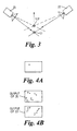
- Figure 5 shows the camera in plan view and illustrates the effect of panning the camera in the direction of arrow 800, the panned position of the camera being shown dotted and referenced as 140.
- the position of the LED's through static with respect to the camera 14, 140 will change relative to the detection cameras 22, 26 and will be in positions indicated at 722, 742 and 762 with the plate 780 now in position 782.
- the detector cameras 22, 26 and associated processing circuitry will be able to calculate any panning movement of the camera in addition to the cameras x,y and z position.
- the camera 14 is shown in two positions, the second position being as a result of the camera being rolled in the direction of arrow 802 on its longitudinal axis 142 (see Figure 7).
- the plate 780 will be in position 784 (shown dotted).
- the LED's 720, 740 and 760 will be in positions 724, 744 and 764.
- the position of LED's 720, 740 and 760 will vary when in positions 724, 744 and 764 relative to the cameras 22, 26 even though these LED's stay in a fixed position with respect to the camera 14.
- the roll of the camera can be measured by the use of the three LED's 720, 740, 760 and the two cameras 22, 26.
- the camera 14 is shown in a first position and (dotted) in a tilted position 144.
- LED 720 is not visible as it is behind LED 760.
- LED's 740, 760 (and 720 not shown) assume positions 746, 766 (and 726) and these new positions are detectable by cameras 22 and 26 and therefore the angle of tilt of camera 14 is also detectable.
- LED's 720, 740 and 760 are not critical but they must be at positions which are visible to cameras 22, 26, preferably in all positions of camera 14. Also, they must be a reasonable distance apart so as to be distinguishable by the detector cameras 11, 26.
- zoom-focus sensors which read and transmit the information in synchronised mode to the TV vertical sync. This information is read into the control unit 46 and thus the system can be operated with a solid uni-color chroma-key panel and with a shoulder mounted camera.
Landscapes
- Engineering & Computer Science (AREA)
- Multimedia (AREA)
- Signal Processing (AREA)
- Studio Circuits (AREA)
- Studio Devices (AREA)
- Length Measuring Devices By Optical Means (AREA)
- Non-Portable Lighting Devices Or Systems Thereof (AREA)
- Processing Of Color Television Signals (AREA)
Description
Claims (20)
- A virtual studio positioning system comprising a chroma-key background panel (12), a television camera (14) situated in a defined front studio area (16) in front of the background panel (12) for imaging a foreground object in front of the background panel, at least one fixed mounted detection unit (22) having a field of view to cover the defined front studio area (16), an emitting device (30) mounted in a fixed relationship with respect to the TV camera or foreground object, said fixed mounted detection (22) unit receiving emissions from said emitting device and producing a detection output signal, processing means (40) for processing the detection output signal of the fixed detection unit to provide at least x and y co-ordinates of the TV camera (14) or foreground object in relation to its position in the defined front studio area (16) and
characterised in that such system comprises as said emitting device (30) a defined structure of at least three LED's (720,740,760) positioned in a fixed relationship with respect to the camera (14) or foreground object to enable calculation of all parameters x,y,z, pan, tilt and roll of the camera or the foreground object, respectively. - A position sensing system a characterised in claim 1, further including a zoom-focus sensor attached to said camera, the system enabling the use of a uni-color background panel for displaying a virtual background.
- A virtual studio positioning system as claimed in claim 1 in which the chroma-key background panel (12) comprises a coded chroma-key panel and including further processing means (44,46) for processing data extracted from said coded chroma-key panel and wherein the zoom-focus information is provided from the coded chroma-key panel.
- A virtual studio positioning system as claimed in claim 1 or claim 2 in which the emitting device (720,740,760) is an LED, operating in the non visible part of the electromagnetic spectrum.
- A virtual studio positioning system as claimed in claim 3 in which the fixed mounted detection unit (22) is a static camera, also sensitive to the non visible part of the electromagnetic spectrum emitted by the LED.
- A virtual studio positioning system as claimed in claim 4 in which both the LEDs (720,740,760) and the static camera operate in the near infra-red.
- A virtual studio positioning system as claimed in any preceding claim in which the LED (720,740,760) is not on continuously but is switched on for a defined time period (228).
- A virtual studio positioning system as claimed in any preceding claim in which the LED (720,740,760) output comprises a coded emission.
- A virtual studio positioning system as claimed in claim 7 in which the detection unit (22) is also gated to receive emissions during a further defined period (227) which is synchronous to the defined time period (228).
- A virtual studio positioning system as claimed in claim 8 in which the defined time period (228) is shorter than the further defined time period (227) and both periods are synchronised (224) to the frame synchronisation of the virtual studio equipment.
- A virtual studio positioning system as claimed in claim 9 in which the LED (720,740,760) is active for a period of approximately 200µsec and the detection device for a period of 100µsec.
- A virtual studio positioning system as claimed in any of claims 1 to 10 in which the fixed mounted detection unit is mounted at a height above the background panel.
- A virtual studio positioning system as claimed in any one of claims 1 to 11 in which a second fixed mounted detection unit (26) is provided.
- A virtual studio positioning system as claimed in claim 13 in which means are provided for triangulating the positions given by the first and second detection units (22,26) to determine the x,y, and z positions of the studio camera or the foreground object.
- A virtual studio positioning system as claimed in any one of claims 3 to 13 in which the detected output signal from said emitting device (720,740,760) is used to constrain the calculation of the further processing means (44,46) to provide more accurate perspective transformation.
- A position sensing system for a TV studio, the system comprising an emission device (30) mounted in a fixed relationship with respect to a television camera or on an object in a defined area, detection means (22) to detect the radiation emitted by said emission device and providing an output signal, processing means (40) for processing the output signal of the detection means to provide an x,y positional map of the camera or the object within the defined area and characterised in that said system further comprises as said emission device a defined structure of at least three LED's (720,740,760) positioned in a fixed relationship with respect to the camera or the object to enable calculation of all parameters x,y,z, pan, tilt and roll of the camera or the object, respectively.
- A position sensing system for a TV studio as claimed in claim 16 in which the emission device (720,740,760) emits radiation within the near infra-red.
- A position sensing system for a TV studio as claimed in claim 16 in which the emission device emits non-continuous radiation only in pulses of defined width (228).
- A position sensing system for a TV studio as claimed in claim 17 in which the detection means is provided with spectral filter means to collect only radiation in the emission spectrum of the emission device and also with temporal filter means to collect radiation only within a defined time period (227), said time period being synchronised to the pulse output of the emission device.
- A position sensing system for a TV studio as claimed in any one of claims 16 to 18 in which a second detection means (26) is provided having a second output signal, the first and second output signals being used to define the position of the object in the x,y and z directions.
Applications Claiming Priority (3)
| Application Number | Priority Date | Filing Date | Title |
|---|---|---|---|
| GB9702636 | 1997-02-01 | ||
| GBGB9702636.3A GB9702636D0 (en) | 1997-02-01 | 1997-02-01 | Virtual studio position sensing system |
| PCT/GB1998/000234 WO1998034410A1 (en) | 1997-02-01 | 1998-01-27 | Virtual studio position sensing system |
Publications (2)
| Publication Number | Publication Date |
|---|---|
| EP0956709A1 EP0956709A1 (en) | 1999-11-17 |
| EP0956709B1 true EP0956709B1 (en) | 2002-04-03 |
Family
ID=10807336
Family Applications (1)
| Application Number | Title | Priority Date | Filing Date |
|---|---|---|---|
| EP98901393A Expired - Lifetime EP0956709B1 (en) | 1997-02-01 | 1998-01-27 | Virtual studio position sensing system |
Country Status (9)
| Country | Link |
|---|---|
| US (2) | US6201579B1 (en) |
| EP (1) | EP0956709B1 (en) |
| JP (1) | JP2001509984A (en) |
| AU (1) | AU5772898A (en) |
| BR (1) | BR9800519A (en) |
| DE (1) | DE69804591T2 (en) |
| GB (1) | GB9702636D0 (en) |
| WO (1) | WO1998034410A1 (en) |
| ZA (1) | ZA98722B (en) |
Cited By (1)
| Publication number | Priority date | Publication date | Assignee | Title |
|---|---|---|---|---|
| WO2020198823A1 (en) * | 2019-03-29 | 2020-10-08 | Globo Comunicação E Participações S.a. | System and method for capturing and projecting images, and use of the system |
Families Citing this family (29)
| Publication number | Priority date | Publication date | Assignee | Title |
|---|---|---|---|---|
| GB9702636D0 (en) | 1997-02-01 | 1997-04-02 | Orad Hi Tech Systems Limited | Virtual studio position sensing system |
| AU2834899A (en) * | 1998-02-18 | 1999-09-06 | Gmd-Forschungszentrum Informationstechnik Gmbh | Camera tracking system for a virtual television or video studio |
| US6965397B1 (en) | 1999-11-22 | 2005-11-15 | Sportvision, Inc. | Measuring camera attitude |
| CN100349188C (en) * | 1999-11-24 | 2007-11-14 | 伊摩信科技有限公司 | Method and system for synchronously integrating video sequences in time and space |
| AU2001253224A1 (en) * | 2000-04-07 | 2001-10-23 | Businger, Peter A. | Automated stroboscoping of video sequences |
| ES2377193T3 (en) * | 2000-10-25 | 2012-03-23 | Shotoku Ltd. | Image capture procedure and image capture system |
| WO2002073955A1 (en) * | 2001-03-13 | 2002-09-19 | Canon Kabushiki Kaisha | Image processing apparatus, image processing method, studio apparatus, storage medium, and program |
| US7116342B2 (en) * | 2003-07-03 | 2006-10-03 | Sportsmedia Technology Corporation | System and method for inserting content into an image sequence |
| US7391424B2 (en) * | 2003-08-15 | 2008-06-24 | Werner Gerhard Lonsing | Method and apparatus for producing composite images which contain virtual objects |
| US7719563B2 (en) * | 2003-12-11 | 2010-05-18 | Angus Richards | VTV system |
| US7209577B2 (en) | 2005-07-14 | 2007-04-24 | Logitech Europe S.A. | Facial feature-localized and global real-time video morphing |
| US7629994B2 (en) * | 2006-07-11 | 2009-12-08 | Sony Corporation | Using quantum nanodots in motion pictures or video games |
| US7767967B2 (en) * | 2006-11-01 | 2010-08-03 | Sony Corporation | Capturing motion using quantum nanodot sensors |
| US8339418B1 (en) * | 2007-06-25 | 2012-12-25 | Pacific Arts Corporation | Embedding a real time video into a virtual environment |
| CN101674418B (en) * | 2008-09-10 | 2013-09-18 | 新奥特(北京)视频技术有限公司 | Method for detecting depth of emcee in virtual studio system |
| JP5227883B2 (en) * | 2009-05-15 | 2013-07-03 | 日本放送協会 | Composite video generation system, lighting control device, and program |
| US8786415B2 (en) * | 2010-02-24 | 2014-07-22 | Sportvision, Inc. | Tracking system using proximity and/or presence |
| US8338725B2 (en) * | 2010-04-29 | 2012-12-25 | Au Optronics Corporation | Camera based touch system |
| US9215383B2 (en) | 2011-08-05 | 2015-12-15 | Sportsvision, Inc. | System for enhancing video from a mobile camera |
| CN102710898B (en) * | 2011-08-26 | 2015-02-18 | 新奥特(北京)视频技术有限公司 | Method and system for synchronously switching foreground and background of color key device |
| US9450671B2 (en) * | 2012-03-20 | 2016-09-20 | Industrial Technology Research Institute | Transmitting and receiving apparatus and method for light communication, and the light communication system thereof |
| ES2518766A1 (en) * | 2014-05-23 | 2014-11-05 | Universidad Politécnica de Madrid | System for determining the position and orientation for a portable device (Machine-translation by Google Translate, not legally binding) |
| US10110822B2 (en) | 2015-06-09 | 2018-10-23 | Fraunhofer-Gesellschaft zur Förderung der angewandten Forschung e.V. | Method for tracking at least one object and method for replacing at least one object by a virtual object in a moving image signal recorded by a camera |
| WO2021068070A1 (en) * | 2019-10-08 | 2021-04-15 | Cast Group Of Companies Inc. | Electronic tracking device for camera and related system for controlling image output of the camera |
| DE102021106488A1 (en) | 2020-12-23 | 2022-06-23 | Arnold & Richter Cine Technik Gmbh & Co. Betriebs Kg | Background display device, background display system, recording system, camera system, digital camera and method for controlling a background display device |
| US11762481B2 (en) * | 2021-04-23 | 2023-09-19 | Lucasfilm Entertainment Company Ltd. | Light capture device |
| US11887251B2 (en) | 2021-04-23 | 2024-01-30 | Lucasfilm Entertainment Company Ltd. | System and techniques for patch color correction for an immersive content production system |
| US11978154B2 (en) | 2021-04-23 | 2024-05-07 | Lucasfilm Entertainment Company Ltd. | System and techniques for lighting adjustment for an immersive content production system |
| US12373999B2 (en) | 2021-04-23 | 2025-07-29 | Lucasfilm Entertainment Company Ltd. | User interfaces for color and lighting adjustments for an immersive content production system |
Family Cites Families (12)
| Publication number | Priority date | Publication date | Assignee | Title |
|---|---|---|---|---|
| US3914540A (en) * | 1974-10-03 | 1975-10-21 | Magicam Inc | Optical node correcting circuit |
| US4769707A (en) * | 1987-05-20 | 1988-09-06 | Fuji Television Incorporated | TV optical effect generating system |
| US5179421A (en) * | 1990-08-20 | 1993-01-12 | Parkervision, Inc. | Remote tracking system particularly for moving picture cameras and method |
| GB9217098D0 (en) * | 1992-08-12 | 1992-09-23 | British Broadcasting Corp | Derivation of studio camera position and motion from the camera image |
| IL109487A (en) * | 1994-04-29 | 1996-09-12 | Orad Hi Tec Systems Ltd | Chromakeying system |
| AU5446896A (en) * | 1995-04-10 | 1996-10-30 | Electrogig Corporation | Hand-held camera tracking for virtual set video production s ystem |
| US5912700A (en) * | 1996-01-10 | 1999-06-15 | Fox Sports Productions, Inc. | System for enhancing the television presentation of an object at a sporting event |
| CA2189109A1 (en) * | 1995-10-30 | 1997-05-01 | Kenji Mitsui | Keying system and composite image producing method |
| US6020931A (en) * | 1996-04-25 | 2000-02-01 | George S. Sheng | Video composition and position system and media signal communication system |
| US5889550A (en) * | 1996-06-10 | 1999-03-30 | Adaptive Optics Associates, Inc. | Camera tracking system |
| US6072537A (en) * | 1997-01-06 | 2000-06-06 | U-R Star Ltd. | Systems for producing personalized video clips |
| GB9702636D0 (en) | 1997-02-01 | 1997-04-02 | Orad Hi Tech Systems Limited | Virtual studio position sensing system |
-
1997
- 1997-02-01 GB GBGB9702636.3A patent/GB9702636D0/en active Pending
-
1998
- 1998-01-27 JP JP53261598A patent/JP2001509984A/en active Pending
- 1998-01-27 EP EP98901393A patent/EP0956709B1/en not_active Expired - Lifetime
- 1998-01-27 AU AU57728/98A patent/AU5772898A/en not_active Abandoned
- 1998-01-27 WO PCT/GB1998/000234 patent/WO1998034410A1/en not_active Ceased
- 1998-01-27 DE DE69804591T patent/DE69804591T2/en not_active Expired - Fee Related
- 1998-01-29 US US09/015,196 patent/US6201579B1/en not_active Expired - Fee Related
- 1998-01-29 ZA ZA98722A patent/ZA98722B/en unknown
- 1998-01-30 BR BR9800519A patent/BR9800519A/en not_active IP Right Cessation
-
2000
- 2000-12-14 US US09/736,996 patent/US6438508B2/en not_active Expired - Fee Related
Cited By (2)
| Publication number | Priority date | Publication date | Assignee | Title |
|---|---|---|---|---|
| WO2020198823A1 (en) * | 2019-03-29 | 2020-10-08 | Globo Comunicação E Participações S.a. | System and method for capturing and projecting images, and use of the system |
| US12101573B2 (en) | 2019-03-29 | 2024-09-24 | Globo Comunicação E Participações S.a. | System for capturing and projecting images, use of the system and method for capturing, projecting and inserting images |
Also Published As
| Publication number | Publication date |
|---|---|
| EP0956709A1 (en) | 1999-11-17 |
| US6438508B2 (en) | 2002-08-20 |
| DE69804591D1 (en) | 2002-05-08 |
| US6201579B1 (en) | 2001-03-13 |
| GB9702636D0 (en) | 1997-04-02 |
| ZA98722B (en) | 1998-08-05 |
| AU5772898A (en) | 1998-08-25 |
| US20010001242A1 (en) | 2001-05-17 |
| BR9800519A (en) | 1999-06-29 |
| DE69804591T2 (en) | 2002-10-31 |
| WO1998034410A1 (en) | 1998-08-06 |
| JP2001509984A (en) | 2001-07-24 |
Similar Documents
| Publication | Publication Date | Title |
|---|---|---|
| US6201579B1 (en) | Virtual studio position sensing system | |
| EP1013080B1 (en) | Virtual studio position sensing system | |
| KR102599609B1 (en) | Control method and electronic device of electronic device | |
| US12075182B2 (en) | Background display device, background display system, recording system, camera system, digital camera and method of controlling a background display device | |
| US20060238617A1 (en) | Systems and methods for night time surveillance | |
| Thomas et al. | A versatile camera position measurement system for virtual reality TV production | |
| US7466359B2 (en) | Image-pickup apparatus and method having distance measuring function | |
| CA2014853C (en) | Light-pen system for projected images | |
| KR101634129B1 (en) | Moving object tracting control system for pan-tilt camera | |
| CA2322020A1 (en) | Camera tracking system for a virtual television or video studio | |
| WO1994015165A1 (en) | Target acquisition training apparatus and method of training in target acquisition | |
| US12058279B2 (en) | Control method of electronic device and electronic device | |
| US11947045B2 (en) | Controlling method for electronic device, and electronic device | |
| JPH10198506A (en) | System for detecting coordinate | |
| EP4369700A1 (en) | Method and system for tracking camera poses | |
| JPH0244995A (en) | Optical direction control method for three-dimensional image display device | |
| GB2352899A (en) | Tracking moving objects | |
| JPH07140225A (en) | Position measuring device and moving body control device using the device | |
| US12477073B2 (en) | LED panel having integrated infrared retroreflectors for video volume production environments | |
| US11902691B2 (en) | LED panel having integrated infrared retroreflectors for video volume production environments | |
| JP2001141457A (en) | Three-dimensional measuring apparatus | |
| JP2005323330A (en) | Indoor observation system | |
| CN115980772A (en) | A ship-borne distributed multi-photoelectric cooperative detection system and detection method | |
| JPH1079841A (en) | Photographing method |
Legal Events
| Date | Code | Title | Description |
|---|---|---|---|
| PUAI | Public reference made under article 153(3) epc to a published international application that has entered the european phase |
Free format text: ORIGINAL CODE: 0009012 |
|
| 17P | Request for examination filed |
Effective date: 19990819 |
|
| AK | Designated contracting states |
Kind code of ref document: A1 Designated state(s): DE FR GB IT |
|
| 17Q | First examination report despatched |
Effective date: 20000510 |
|
| GRAG | Despatch of communication of intention to grant |
Free format text: ORIGINAL CODE: EPIDOS AGRA |
|
| GRAG | Despatch of communication of intention to grant |
Free format text: ORIGINAL CODE: EPIDOS AGRA |
|
| GRAH | Despatch of communication of intention to grant a patent |
Free format text: ORIGINAL CODE: EPIDOS IGRA |
|
| GRAH | Despatch of communication of intention to grant a patent |
Free format text: ORIGINAL CODE: EPIDOS IGRA |
|
| REG | Reference to a national code |
Ref country code: GB Ref legal event code: IF02 |
|
| GRAA | (expected) grant |
Free format text: ORIGINAL CODE: 0009210 |
|
| AK | Designated contracting states |
Kind code of ref document: B1 Designated state(s): DE FR GB IT |
|
| REF | Corresponds to: |
Ref document number: 69804591 Country of ref document: DE Date of ref document: 20020508 |
|
| ET | Fr: translation filed | ||
| PLBE | No opposition filed within time limit |
Free format text: ORIGINAL CODE: 0009261 |
|
| STAA | Information on the status of an ep patent application or granted ep patent |
Free format text: STATUS: NO OPPOSITION FILED WITHIN TIME LIMIT |
|
| 26N | No opposition filed |
Effective date: 20030106 |
|
| PGFP | Annual fee paid to national office [announced via postgrant information from national office to epo] |
Ref country code: IT Payment date: 20080130 Year of fee payment: 11 Ref country code: GB Payment date: 20080123 Year of fee payment: 11 Ref country code: DE Payment date: 20080124 Year of fee payment: 11 |
|
| PGFP | Annual fee paid to national office [announced via postgrant information from national office to epo] |
Ref country code: FR Payment date: 20080108 Year of fee payment: 11 |
|
| GBPC | Gb: european patent ceased through non-payment of renewal fee |
Effective date: 20090127 |
|
| PG25 | Lapsed in a contracting state [announced via postgrant information from national office to epo] |
Ref country code: DE Free format text: LAPSE BECAUSE OF NON-PAYMENT OF DUE FEES Effective date: 20090801 |
|
| REG | Reference to a national code |
Ref country code: FR Ref legal event code: ST Effective date: 20091030 |
|
| PG25 | Lapsed in a contracting state [announced via postgrant information from national office to epo] |
Ref country code: GB Free format text: LAPSE BECAUSE OF NON-PAYMENT OF DUE FEES Effective date: 20090127 |
|
| PG25 | Lapsed in a contracting state [announced via postgrant information from national office to epo] |
Ref country code: FR Free format text: LAPSE BECAUSE OF NON-PAYMENT OF DUE FEES Effective date: 20090202 |
|
| PG25 | Lapsed in a contracting state [announced via postgrant information from national office to epo] |
Ref country code: IT Free format text: LAPSE BECAUSE OF NON-PAYMENT OF DUE FEES Effective date: 20090127 |