EP0956384B1 - Diagnostic system for a jacquard machine - Google Patents
Diagnostic system for a jacquard machine Download PDFInfo
- Publication number
- EP0956384B1 EP0956384B1 EP97949009A EP97949009A EP0956384B1 EP 0956384 B1 EP0956384 B1 EP 0956384B1 EP 97949009 A EP97949009 A EP 97949009A EP 97949009 A EP97949009 A EP 97949009A EP 0956384 B1 EP0956384 B1 EP 0956384B1
- Authority
- EP
- European Patent Office
- Prior art keywords
- hooks
- shed
- heald
- pattern
- jacquard machine
- Prior art date
- Legal status (The legal status is an assumption and is not a legal conclusion. Google has not performed a legal analysis and makes no representation as to the accuracy of the status listed.)
- Expired - Lifetime
Links
- 230000000007 visual effect Effects 0.000 claims abstract description 18
- 238000009941 weaving Methods 0.000 claims abstract description 17
- 238000000034 method Methods 0.000 claims description 5
- 238000002405 diagnostic procedure Methods 0.000 claims description 2
- 238000001514 detection method Methods 0.000 description 2
- 238000010586 diagram Methods 0.000 description 1
- 239000004744 fabric Substances 0.000 description 1
- 239000003973 paint Substances 0.000 description 1
- 238000010422 painting Methods 0.000 description 1
- 230000000717 retained effect Effects 0.000 description 1
Images
Classifications
-
- D—TEXTILES; PAPER
- D03—WEAVING
- D03C—SHEDDING MECHANISMS; PATTERN CARDS OR CHAINS; PUNCHING OF CARDS; DESIGNING PATTERNS
- D03C3/00—Jacquards
- D03C3/24—Features common to jacquards of different types
-
- D—TEXTILES; PAPER
- D03—WEAVING
- D03C—SHEDDING MECHANISMS; PATTERN CARDS OR CHAINS; PUNCHING OF CARDS; DESIGNING PATTERNS
- D03C17/00—Card-punching apparatus
- D03C17/06—Card-punching apparatus automatic, i.e. design scanned optically or otherwise to control punching apparatus or to control loom jacquard directly
-
- D—TEXTILES; PAPER
- D03—WEAVING
- D03D—WOVEN FABRICS; METHODS OF WEAVING; LOOMS
- D03D51/00—Driving, starting, or stopping arrangements; Automatic stop motions
- D03D51/18—Automatic stop motions
- D03D51/44—Automatic stop motions acting on defective operation of loom mechanisms
- D03D51/46—Automatic stop motions acting on defective operation of loom mechanisms of shedding mechanisms
Definitions
- the present invention relates to a diagnostic system for a jacquard machine, in particular, a jacquard machine for a weaving loom.
- Jacquard machines for weaving looms usually include a plurality of heald hooks arranged in rows extending in the weft direction, the rows being located side by side in the warp direction.
- Each row of hooks is acted upon by a reciprocating knife such that selected hooks in the row are moved from one shed position to and held at another shed position during a pick in the weaving cycle.
- the knife may move only selected hooks from said one shed position or may move all hooks from said one shed position such that selected hooks can be retained at said one shed position.
- a diagnostic system for a jacquard machine having a plurality of heald hooks movable between at least two discrete shed positions, the system including visual sensing means for producing a visual image of hooks located at one of said shed positions during each weaving cycle, and control means for comparing said visual image with a predetermined shed pattern for each corresponding weaving cycle in order to determine whether or not all the appropriate hooks have been selected to define the required shed pattern.
- the visual sensing means comprises at least one video camera located to one side of the jacquard machine so as to view the heald hooks at an inclined angle.
- datum means are provided to enable the control means to determine the location of each heald hook.
- the datum means may be in the form of a pattern located around the periphery of the rows of heald hooks to thereby enable the control means to create an orthogonal virtual grid of imaginary lines, the location of each hook being at the intersection of said imaginary lines.
- the heald hooks may be adapted to make them more visibly distinct, for example by being coated with a suitable paint.
- a diagnostic method for a jacquard machine having a plurality of heald hooks movable between at least two shed positions, the method including the steps of creating a visual image of hooks located at one of said shed positions during each weaving cycle, and comparing said visual image with a predetermined shed pattern for each corresponding weaving cycle in order to determine whether or not all the appropriate hooks have been selected to define the required shed pattern.
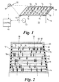
- a jacquard machine 10 is schematically shown in Figures 1 and 2 having a frame 12 in which a plurality of lifting knives 14 are mounted for reciprocal movement.
- Each knife 14 co-operates with a row 15 of heald hooks 16, there being shown eight rows 15 of heald hooks and eight lifting knives. It will be appreciated that any number of knives 14 and corresponding rows 15 may be provided. Each row 15 contains the same number of heald hooks 16. The heald hooks 16 are regularly spaced along the corresponding knife and are aligned with heald hooks 16 located at the same position on neighbouring rows.
- heald hooks 16 are also arranged in rows 18 which are spaced side by side along the knives 14.
- heald hooks 16 are arranged in an orthogonal grid pattern composed of rows 15 and rows 18, each heald hook 16 being located at the intersection of each row 15 and row 18.
- a diagnostic system which includes a visual sensing means 30 and an electronic control 40.
- the visual sensing means 30 is preferably in the form of a video camera 31 which is mounted above and to one side of the top of the jacquard machine 10 so as to view hooks 16 as they rise to their upper shed position.
- the image viewed by the camera is schematically shown in Figure 2.
- the electronic control 40 preferably comprise a computer which receives the video image from the camera preferably via a digitizer interface.
- the computer is arranged to receive an operating signal O during each weaving cycle.
- the operating signal O may be generated by for example a sensor on the drive shaft 42 of the jacquard in the case of a jacquard having mechanically operated pattern selection or may be generated from the electronic control of a jacquard having electronically controlled pattern selection.
- the computer On receipt of signal O , the computer is arranged to grab an image from the camera and use the image to identify the presence of hooks located at their upper shed position and then determine whether or not all selected hooks have been raised.
- the camera is a monochrome camera and preferably the upper portion 16 a of the hooks 16 have been adapted, for example by painting to define a high contrast with their background.
- the upper portions 16 a and painted white so that the upper portions 16 a when viewed by the camera appear light compared to the background.
- the computer could be programmed with a look-up map identifying the locations of each hook. However this would require the camera to be accurately positioned and for it to remain in that position during its working life. Accordingly, it is preferred to provide a system whereby the computer can determine the grid locations of the heald hooks using the image produced by the camera.
- a first method is to locate targets at predetermined positions on the jacquard frame 12.
- a pair of targets 50 may be provided at diagonally opposite corners of the jacquard frame 12.
- the shape and contrast of the target 50 is chosen so as to be easily recognised by the software and provides a pair of fixed reference points in the image produced by the camera.
- a set-up routine Prior to a weaving operation, a set-up routine is performed.
- the jacquard machine is then run with a predetermined weave pattern, for example a plain weave, and the software reconciles the pattern of the lifted hooks 16 in the image with the predetermined pattern sequence and provides and stores in memory co-ordinates in the image for each hook grid location.
- the computer is able to accurately monitor lifting of each hook as long as the camera position does not change. Accordingly the computer preferably continually monitors the co-ordinates of the viewed targets 50 and compares them with the co-ordinates stored during set-up. If the comparison shows that the camera position has changed, weaving is stopped and a new set-up routine is performed.
- a rectangular target 60 is provided on the top of the machine frame 12 and is arranged to identify the position of rows 15 and rows 18.
- the target 60 for example as shown in Figure 2 consists of dark areas 81 contrasting with light areas 82.
- the dark areas 81 may for example be aligned with each row 15 or 18.
- the software is arranged to scan the image and using the target 60 create a virtual grid of imaginary orthogonal lines.
- the software determines the cross-over points of the orthogonal lines and thereby determines the grid location of each heald hook 16. Scanning of the image to create the virtual grid occurs during each weaving cycle. Accordingly movement of the camera does not affect determination of the grid location of the each hook.
- the scanned information used to determine the virtual grid will automatically compensate for perspective errors in the image caused by some hooks being closer to the camera than others.
Landscapes
- Engineering & Computer Science (AREA)
- Textile Engineering (AREA)
- Looms (AREA)
- Endoscopes (AREA)
- Details Of Flowmeters (AREA)
- Selective Calling Equipment (AREA)
- Auxiliary Weaving Apparatuses, Weavers' Tools, And Shuttles (AREA)
Abstract
Description
Claims (6)
- A diagnostic system for a jacquard machine (10) having a plurality of heald hooks (16) moveable between at least two discrete shed positions, the system including visual sensing means (30) for producing a visual image of hooks (16) located at one of said shed positions during each weaving cycle, and control means (40) for comparing said visual image with a predetermined shed pattern for each corresponding weaving cycle in order to determine whether or not all the appropriate hooks (16) have been selected to define the required shed pattern.
- A system according to Claim 1 wherein the visual sensing means (30) comprises at least one video camera (31) located to one side of the jacquard machine (10) so as to view the heald hooks (16) at an inclined angle.
- A system according to Claim 1 or 2 wherein datum means are provided to enable the control means (30) to determine the location of each heald hook (16).
- A system according to Claim 3 wherein the datum means is in the form of a pattern located around the periphery of the rows of heald hooks (16) to thereby enable the control means (30) to create an orthogonal virtual grid of imaginary lines, the location of each hook (16) being at the intersection of said imaginary lines.
- A system according to any proceeding claim wherein the hooks (16) are adapted to make them visibly distinct.
- A diagnostic method for a jacquard machine (10) having a plurality of heald hooks (16) moveable between at least two shed positions, the method including the steps of creating a visual image of hooks (16) located at one of said shed positions during each weaving cycle, and comparing said visual image with a predetermined shed pattern for each corresponding weaving cycle in order to determine whether or not all the appropriate hooks (16) have been selected to define the required shed pattern.
Applications Claiming Priority (3)
| Application Number | Priority Date | Filing Date | Title |
|---|---|---|---|
| GB9626432 | 1996-12-19 | ||
| GBGB9626432.0A GB9626432D0 (en) | 1996-12-19 | 1996-12-19 | Diagnostic system for a jacquard machine |
| PCT/GB1997/003366 WO1998027254A1 (en) | 1996-12-19 | 1997-12-17 | Diagnostic system for a jacquard machine |
Publications (2)
| Publication Number | Publication Date |
|---|---|
| EP0956384A1 EP0956384A1 (en) | 1999-11-17 |
| EP0956384B1 true EP0956384B1 (en) | 2002-11-27 |
Family
ID=10804719
Family Applications (1)
| Application Number | Title | Priority Date | Filing Date |
|---|---|---|---|
| EP97949009A Expired - Lifetime EP0956384B1 (en) | 1996-12-19 | 1997-12-17 | Diagnostic system for a jacquard machine |
Country Status (7)
| Country | Link |
|---|---|
| US (1) | US6102079A (en) |
| EP (1) | EP0956384B1 (en) |
| JP (1) | JP2001507087A (en) |
| AT (1) | ATE228587T1 (en) |
| DE (1) | DE69717496D1 (en) |
| GB (1) | GB9626432D0 (en) |
| WO (1) | WO1998027254A1 (en) |
Cited By (1)
| Publication number | Priority date | Publication date | Assignee | Title |
|---|---|---|---|---|
| EP3717685B1 (en) * | 2017-11-29 | 2023-12-20 | Uster Technologies Ltd. | Methods and systems for triggered on-loom fabric inspection |
Families Citing this family (4)
| Publication number | Priority date | Publication date | Assignee | Title |
|---|---|---|---|---|
| DE10061717B4 (en) * | 2000-12-12 | 2006-01-26 | Lindauer Dornier Gmbh | Drive arrangement for a weaving machine and shedding machine |
| BE1014133A3 (en) * | 2001-04-20 | 2003-05-06 | Picanol Nv | Method for optimizing a textile production and establishments to apply this procedure. |
| FR2830659B1 (en) * | 2001-08-30 | 2006-10-13 | Groupe Sofide | VEHICLE TELECONTROL AND TELESURVEILLANCE SYSTEM BY A MANAGEMENT AND MONITORING CENTER |
| TWM493278U (en) * | 2014-10-21 | 2015-01-11 | Deertex Inc | Footwear assembly with breathable and wear-resistant woven vamp |
Family Cites Families (15)
| Publication number | Priority date | Publication date | Assignee | Title |
|---|---|---|---|---|
| GB711955A (en) * | 1949-08-12 | 1954-07-14 | Electrotext Corp | Improvements in or relating to an electrically controlled loom |
| US3117598A (en) * | 1960-12-08 | 1964-01-14 | Courtaulds Ltd | Textile manufacturing process and apparatus |
| CH388211A (en) * | 1961-04-26 | 1965-02-15 | Rueti Ag Maschf | Device for controlling the shaft movement in looms using a design card |
| CH473251A (en) * | 1967-04-21 | 1969-05-31 | App Fabrik Ag | Method for operating the sinkers of a jacquard machine or punching needles of a jacquard card punching machine |
| JPS5129563A (en) * | 1974-08-30 | 1976-03-12 | Mitsubishi Rayon Co | |
| US4135554A (en) * | 1976-10-16 | 1979-01-23 | Miyuki Gotoh | Device for detecting the loss of tension of a warp yarn in a weaving loom |
| FR2476694A1 (en) * | 1980-02-22 | 1981-08-28 | Verdol Sa | IMPROVED DEVICE FOR OPENING THE STEP ON A WEAVING |
| SE448002B (en) * | 1983-10-07 | 1987-01-12 | Asea Ab | OPTICAL UPPER AND MONITORING OF WOVEN PRODUCTS AT MACHINE WEAR |
| DE3618467A1 (en) * | 1986-06-02 | 1987-01-08 | Uwe Dipl Ing Thieme | Control for weaving machines |
| JPS6335847A (en) * | 1986-07-24 | 1988-02-16 | 村田機械株式会社 | Method for detecting lease falling for detecting lease falling in dobby machine |
| IT1216766B (en) * | 1988-02-15 | 1990-03-08 | Bobbio Benedetto | Clamping spikes control system |
| GB8817765D0 (en) * | 1988-07-26 | 1988-09-01 | Palmer R L | Loom control |
| JP2643539B2 (en) * | 1990-06-04 | 1997-08-20 | 株式会社豊田自動織機製作所 | Loom diagnostic system |
| DE4142356A1 (en) * | 1990-12-28 | 1992-07-02 | Nissan Motor | WOMB MONITORING SYSTEM FOR A WEAVING MACHINE |
| GB2312440A (en) * | 1996-04-26 | 1997-10-29 | Scapa Group Plc | Jacquard mechanism |
-
1996
- 1996-12-19 GB GBGB9626432.0A patent/GB9626432D0/en active Pending
-
1997
- 1997-12-17 EP EP97949009A patent/EP0956384B1/en not_active Expired - Lifetime
- 1997-12-17 WO PCT/GB1997/003366 patent/WO1998027254A1/en not_active Ceased
- 1997-12-17 AT AT97949009T patent/ATE228587T1/en not_active IP Right Cessation
- 1997-12-17 JP JP52743498A patent/JP2001507087A/en active Pending
- 1997-12-17 DE DE69717496T patent/DE69717496D1/en not_active Expired - Lifetime
- 1997-12-17 US US09/319,919 patent/US6102079A/en not_active Expired - Fee Related
Cited By (1)
| Publication number | Priority date | Publication date | Assignee | Title |
|---|---|---|---|---|
| EP3717685B1 (en) * | 2017-11-29 | 2023-12-20 | Uster Technologies Ltd. | Methods and systems for triggered on-loom fabric inspection |
Also Published As
| Publication number | Publication date |
|---|---|
| EP0956384A1 (en) | 1999-11-17 |
| DE69717496D1 (en) | 2003-01-09 |
| GB9626432D0 (en) | 1997-02-05 |
| JP2001507087A (en) | 2001-05-29 |
| WO1998027254A1 (en) | 1998-06-25 |
| US6102079A (en) | 2000-08-15 |
| ATE228587T1 (en) | 2002-12-15 |
Similar Documents
| Publication | Publication Date | Title |
|---|---|---|
| US9909238B2 (en) | Monitoring device for a weaving machine, weaving machine, and method for monitoring | |
| WO1992008967A1 (en) | Methods and apparatus for fabric inspection | |
| US6102079A (en) | Visual diagnostic system for a jacquard machine | |
| US5093797A (en) | Apparatus for inspecting packaged electronic device | |
| US5165454A (en) | Detection of warp in reed dent before loom start up | |
| EP1396562B1 (en) | Method of displaying content of defective weaving of a loom and display unit for displaying content of defective weaving of the loom | |
| US5265650A (en) | Position sensor for an electronic rotary dobby | |
| US5911247A (en) | Jacquard mechanism for creating a shed in a loom | |
| CN1106573C (en) | Device for automatically monitoring textile surface | |
| US4827986A (en) | Harness skip detecting method in dobby | |
| EP0774538A1 (en) | Shedding control method and apparatus for carrying out the same | |
| EP1247886B1 (en) | Method and apparatus for driving a loom | |
| CN111118692A (en) | Method and device for rapidly detecting pattern knitting error of jacquard | |
| EP0307025B1 (en) | Method for monitoring warp breaks on weaving machines, and a device which uses this method | |
| US4527597A (en) | Dobby | |
| GB2286601A (en) | Gripper axminster loom | |
| JPS6411735B2 (en) | ||
| EP0802995A1 (en) | A reed drawing-in method of looms and an apparatus used in the same | |
| US5791381A (en) | Process for determining the arrangement and the step sequence of heald shafts of a heald loom | |
| EP0589830A2 (en) | Display device in a loom | |
| EP1464745A2 (en) | Weft bar preventing apparatus | |
| EP0927782A1 (en) | Method for weaving a pile fabric, with application of weave corrections | |
| JP2924095B2 (en) | Operating method of loom equipped with electronic dobby shedding device | |
| JPH0791724B2 (en) | Pattern pattern input setting method and pattern pattern abnormality display method for electronic dobby loom | |
| EP1439250A2 (en) | Loom with filling bar preventing function |
Legal Events
| Date | Code | Title | Description |
|---|---|---|---|
| PUAI | Public reference made under article 153(3) epc to a published international application that has entered the european phase |
Free format text: ORIGINAL CODE: 0009012 |
|
| 17P | Request for examination filed |
Effective date: 19990703 |
|
| AK | Designated contracting states |
Kind code of ref document: A1 Designated state(s): AT BE CH DE DK ES FI FR GB GR IE IT LI NL PT SE |
|
| GRAG | Despatch of communication of intention to grant |
Free format text: ORIGINAL CODE: EPIDOS AGRA |
|
| 17Q | First examination report despatched |
Effective date: 20011018 |
|
| RIN1 | Information on inventor provided before grant (corrected) |
Inventor name: SILLEM, ROBIN FRANK HAMILTON, NTH. EL. TECH. LTD. Inventor name: CROUCHER, EWAN, NORTHERN ELECTR. TECHN. LTD. |
|
| GRAG | Despatch of communication of intention to grant |
Free format text: ORIGINAL CODE: EPIDOS AGRA |
|
| GRAH | Despatch of communication of intention to grant a patent |
Free format text: ORIGINAL CODE: EPIDOS IGRA |
|
| GRAH | Despatch of communication of intention to grant a patent |
Free format text: ORIGINAL CODE: EPIDOS IGRA |
|
| GRAA | (expected) grant |
Free format text: ORIGINAL CODE: 0009210 |
|
| AK | Designated contracting states |
Kind code of ref document: B1 Designated state(s): AT BE CH DE DK ES FI FR GB GR IE IT LI NL PT SE |
|
| PG25 | Lapsed in a contracting state [announced via postgrant information from national office to epo] |
Ref country code: NL Free format text: LAPSE BECAUSE OF FAILURE TO SUBMIT A TRANSLATION OF THE DESCRIPTION OR TO PAY THE FEE WITHIN THE PRESCRIBED TIME-LIMIT Effective date: 20021127 Ref country code: LI Free format text: LAPSE BECAUSE OF FAILURE TO SUBMIT A TRANSLATION OF THE DESCRIPTION OR TO PAY THE FEE WITHIN THE PRESCRIBED TIME-LIMIT Effective date: 20021127 Ref country code: IT Free format text: LAPSE BECAUSE OF FAILURE TO SUBMIT A TRANSLATION OF THE DESCRIPTION OR TO PAY THE FEE WITHIN THE PRESCRIBED TIME-LIMIT;WARNING: LAPSES OF ITALIAN PATENTS WITH EFFECTIVE DATE BEFORE 2007 MAY HAVE OCCURRED AT ANY TIME BEFORE 2007. THE CORRECT EFFECTIVE DATE MAY BE DIFFERENT FROM THE ONE RECORDED. Effective date: 20021127 Ref country code: GR Free format text: LAPSE BECAUSE OF FAILURE TO SUBMIT A TRANSLATION OF THE DESCRIPTION OR TO PAY THE FEE WITHIN THE PRESCRIBED TIME-LIMIT Effective date: 20021127 Ref country code: FR Free format text: LAPSE BECAUSE OF FAILURE TO SUBMIT A TRANSLATION OF THE DESCRIPTION OR TO PAY THE FEE WITHIN THE PRESCRIBED TIME-LIMIT Effective date: 20021127 Ref country code: FI Free format text: LAPSE BECAUSE OF FAILURE TO SUBMIT A TRANSLATION OF THE DESCRIPTION OR TO PAY THE FEE WITHIN THE PRESCRIBED TIME-LIMIT Effective date: 20021127 Ref country code: CH Free format text: LAPSE BECAUSE OF FAILURE TO SUBMIT A TRANSLATION OF THE DESCRIPTION OR TO PAY THE FEE WITHIN THE PRESCRIBED TIME-LIMIT Effective date: 20021127 Ref country code: BE Free format text: LAPSE BECAUSE OF FAILURE TO SUBMIT A TRANSLATION OF THE DESCRIPTION OR TO PAY THE FEE WITHIN THE PRESCRIBED TIME-LIMIT Effective date: 20021127 Ref country code: AT Free format text: LAPSE BECAUSE OF FAILURE TO SUBMIT A TRANSLATION OF THE DESCRIPTION OR TO PAY THE FEE WITHIN THE PRESCRIBED TIME-LIMIT Effective date: 20021127 |
|
| REF | Corresponds to: |
Ref document number: 228587 Country of ref document: AT Date of ref document: 20021215 Kind code of ref document: T |
|
| REG | Reference to a national code |
Ref country code: GB Ref legal event code: FG4D |
|
| REG | Reference to a national code |
Ref country code: CH Ref legal event code: EP |
|
| PG25 | Lapsed in a contracting state [announced via postgrant information from national office to epo] |
Ref country code: IE Free format text: LAPSE BECAUSE OF NON-PAYMENT OF DUE FEES Effective date: 20021217 |
|
| REG | Reference to a national code |
Ref country code: IE Ref legal event code: FG4D |
|
| REF | Corresponds to: |
Ref document number: 69717496 Country of ref document: DE Date of ref document: 20030109 |
|
| PG25 | Lapsed in a contracting state [announced via postgrant information from national office to epo] |
Ref country code: SE Free format text: LAPSE BECAUSE OF FAILURE TO SUBMIT A TRANSLATION OF THE DESCRIPTION OR TO PAY THE FEE WITHIN THE PRESCRIBED TIME-LIMIT Effective date: 20030227 Ref country code: PT Free format text: LAPSE BECAUSE OF FAILURE TO SUBMIT A TRANSLATION OF THE DESCRIPTION OR TO PAY THE FEE WITHIN THE PRESCRIBED TIME-LIMIT Effective date: 20030227 Ref country code: GB Free format text: LAPSE BECAUSE OF NON-PAYMENT OF DUE FEES Effective date: 20030227 Ref country code: DK Free format text: LAPSE BECAUSE OF FAILURE TO SUBMIT A TRANSLATION OF THE DESCRIPTION OR TO PAY THE FEE WITHIN THE PRESCRIBED TIME-LIMIT Effective date: 20030227 |
|
| PG25 | Lapsed in a contracting state [announced via postgrant information from national office to epo] |
Ref country code: DE Free format text: LAPSE BECAUSE OF FAILURE TO SUBMIT A TRANSLATION OF THE DESCRIPTION OR TO PAY THE FEE WITHIN THE PRESCRIBED TIME-LIMIT Effective date: 20030228 |
|
| NLV1 | Nl: lapsed or annulled due to failure to fulfill the requirements of art. 29p and 29m of the patents act | ||
| PG25 | Lapsed in a contracting state [announced via postgrant information from national office to epo] |
Ref country code: ES Free format text: LAPSE BECAUSE OF FAILURE TO SUBMIT A TRANSLATION OF THE DESCRIPTION OR TO PAY THE FEE WITHIN THE PRESCRIBED TIME-LIMIT Effective date: 20030529 |
|
| REG | Reference to a national code |
Ref country code: CH Ref legal event code: PL |
|
| EN | Fr: translation not filed | ||
| REG | Reference to a national code |
Ref country code: IE Ref legal event code: MM4A |
|
| PLBE | No opposition filed within time limit |
Free format text: ORIGINAL CODE: 0009261 |
|
| STAA | Information on the status of an ep patent application or granted ep patent |
Free format text: STATUS: NO OPPOSITION FILED WITHIN TIME LIMIT |
|
| GBPC | Gb: european patent ceased through non-payment of renewal fee | ||
| 26N | No opposition filed |
Effective date: 20030828 |