EP0956251B1 - Device for transporting products - Google Patents
Device for transporting products Download PDFInfo
- Publication number
- EP0956251B1 EP0956251B1 EP98900071A EP98900071A EP0956251B1 EP 0956251 B1 EP0956251 B1 EP 0956251B1 EP 98900071 A EP98900071 A EP 98900071A EP 98900071 A EP98900071 A EP 98900071A EP 0956251 B1 EP0956251 B1 EP 0956251B1
- Authority
- EP
- European Patent Office
- Prior art keywords
- horizontal
- oscillations
- elements
- adjustable
- directions
- Prior art date
- Legal status (The legal status is an assumption and is not a legal conclusion. Google has not performed a legal analysis and makes no representation as to the accuracy of the status listed.)
- Expired - Lifetime
Links
Images

Classifications
-
- B—PERFORMING OPERATIONS; TRANSPORTING
- B65—CONVEYING; PACKING; STORING; HANDLING THIN OR FILAMENTARY MATERIAL
- B65G—TRANSPORT OR STORAGE DEVICES, e.g. CONVEYORS FOR LOADING OR TIPPING, SHOP CONVEYOR SYSTEMS OR PNEUMATIC TUBE CONVEYORS
- B65G1/00—Storing articles, individually or in orderly arrangement, in warehouses or magazines
- B65G1/02—Storage devices
- B65G1/04—Storage devices mechanical
- B65G1/0478—Storage devices mechanical for matrix-arrangements
-
- B—PERFORMING OPERATIONS; TRANSPORTING
- B65—CONVEYING; PACKING; STORING; HANDLING THIN OR FILAMENTARY MATERIAL
- B65G—TRANSPORT OR STORAGE DEVICES, e.g. CONVEYORS FOR LOADING OR TIPPING, SHOP CONVEYOR SYSTEMS OR PNEUMATIC TUBE CONVEYORS
- B65G27/00—Jigging conveyors
-
- B—PERFORMING OPERATIONS; TRANSPORTING
- B65—CONVEYING; PACKING; STORING; HANDLING THIN OR FILAMENTARY MATERIAL
- B65G—TRANSPORT OR STORAGE DEVICES, e.g. CONVEYORS FOR LOADING OR TIPPING, SHOP CONVEYOR SYSTEMS OR PNEUMATIC TUBE CONVEYORS
- B65G27/00—Jigging conveyors
- B65G27/34—Jigging conveyors comprising a series of co-operating units
-
- B—PERFORMING OPERATIONS; TRANSPORTING
- B65—CONVEYING; PACKING; STORING; HANDLING THIN OR FILAMENTARY MATERIAL
- B65G—TRANSPORT OR STORAGE DEVICES, e.g. CONVEYORS FOR LOADING OR TIPPING, SHOP CONVEYOR SYSTEMS OR PNEUMATIC TUBE CONVEYORS
- B65G47/00—Article or material-handling devices associated with conveyors; Methods employing such devices
- B65G47/22—Devices influencing the relative position or the attitude of articles during transit by conveyors
- B65G47/24—Devices influencing the relative position or the attitude of articles during transit by conveyors orientating the articles
- B65G47/244—Devices influencing the relative position or the attitude of articles during transit by conveyors orientating the articles by turning them about an axis substantially perpendicular to the conveying plane
Definitions
- a transport device is known from US-A-3 174 613, in which between two spaced apart conveyor belts with several rows of rollers with the same conveying direction parallel, horizontal roller axes arranged per row are. The roles are either at the orbital speed conveyor belts or at a speed 1.4 times faster driven. Your upper, common tangent plane corresponds to the top of the conveyor belts.
- the axes of the Rollers of each row can move together by 45 ° from a basic position be pivoted in which they are perpendicular to the conveying direction of the conveyor belts are. Promote in this swung out position the rolls of the products delivered by the first conveyor belt, namely glass panels on a cross conveyor belt.
- From GB-A-2 259 900 is a conveyor device according to the preamble of claims 1 and 2, in which the products are known an almost horizontal table in one of the four selectable Directions can be transported.
- the table consists of a large number of table elements arranged side by side, the translationally synchronous in both directions parallel to the table level swing back and forth. Each table element is additional driven oscillator in the vertical direction, these vertical vibrations synchronized with the horizontal vibrations are.
- the present invention has for its object a device to create the above type with simple construction allows easy adjustment of the transport speed. This task is accomplished through the combination of features of the claims solved.
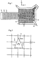
- the device is schematic in plan in the Application shown in a packaging machine.
- the device consists of a horizontal square table 10, the from a multitude of closely spaced square table elements 11 there.
- rows 10 of products 14 are delivered to the table 10.
- the products 14 are in the x direction conveyed and distributed in the y direction and, if necessary, rotated to fill them into packaging container 15 on the right edge of the table.
- the containers 15 are fed via a separate conveyor 16 and then transported for further packaging.
- Each element 11 can have a product resting on it in each transport in any direction.
- the floor plan of the elements 11 does not necessarily have to be be square. It can also be rectangular, triangular or hexagonal his. Other polygonal shapes are possible, too the elements 11 are not uniform in this case.
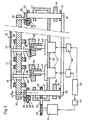
- FIG 3 is a cross section through part of a first Embodiment shown.
- a frame 20 there are two drive shafts 21 rotatable with vertical axis and axially immovable stored.
- One shaft 21 is via pulleys 22 and a toothed belt 23 via a controller 49 by a speed-controllable Drive motor 24 driven.
- a guide member 25 is attached at the top of the Shafts 21, a guide member 25 is attached.
- a carriage 26 is displaceable transversely to the axis of the shafts 21 guided and lockable by means of screws 27, which Grip through longitudinal slots 28 of link 25.
- the sled 26 each carry an eccentric pin 29 parallel to the shafts 21. By loosening the screws 27 and moving the slide 26 the eccentricity a of the pin 29 can be adjusted.
- the Pins 29 are in a common, horizontal support plate 30 rotatably mounted. At the lower end there is one on each of the shafts 21 Flange 31 attached, which another, not adjustable Eccentric pin 32 carries. The eccentricity of these pins 32 is offset by 90 ° relative to that of the pin 29.
- the pins 32 are rotatably mounted in a coupling rod 33. That’s why two shafts 21 rotatably connected together. While running Motor 24 guides the support plate 30 in a circular motion in its Level off. There is still one eccentric mass on each of the shafts 21 34 attached to balance the balance by the support plate 30.
- Each table element 11 is vertically parallel by means of leaf springs 39 attached to itself slidably on the plate 30.
- Each element 11 has a tappet 40 with a spherical cap in the center End face 41 from.
- the measure of eccentricity the pin 29 laterally offset from the axis of the plunger 40 a servo motor or stepper motor 42 is attached to the frame 20.
- the motor 42 has a vertical output shaft 43.
- On the Shaft 43 is a cylindrical pin 44 with an axis to the Fixed shaft 43 inclined axis.
- On the pin 44 is a cylindrical shoe 45 coaxially attached.
- the shoe 45 has one sloping, flat end face 46 on which the surface 41 of the Tappet 40 rests.
- the angle which the surface 46 has with a Includes radial plane of the shoe 45 corresponds to the angle under which the axes of the shaft 43 and the pin 44 cross. By turning the shoe 45 relative to the pin 44 can therefore be the inclination of the surface 46 with respect to one Set the horizontal level from 0 to the maximum value shown.
- Each motor 42 can be individually controlled by a controller 48, so that the surfaces 46 are individually selectable Are inclined towards.
- the controls 48, 49 are by a common control device 50 controlled.
- the surface of the Table 10 can still by a thin, flexible plate 47 to Example a film made of polyurethane or another plastic be covered, which the spaces 48 between the Bridges table elements 11. This increases the risk of contamination reduced.
- the operation of the device described is as follows:
- the motor 24 rotates at the set, constant speed of for example 10 to 30 Hz, so that the table elements 11 a Carry out a circular motion in your plane, for example with a radius of 5 mm.
- the frequency, the radius a and the stroke h are selected so that the acceleration of the table elements 11 down at least in the area of the top dead center of the lifting vibration is greater than gravitational acceleration, so that Product periodically stands out from the element 11 in question.
- the frequency and eccentricity a is set in this case so that the products 14 at least in phases, namely when the elements accelerate 11 slide down on the surface of the elements 11. At the upward acceleration is the frictional force between the elements 11 and the product 14 larger than during acceleration down so that even in this case a translatory movement of the products 14 on the table 10.
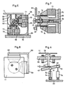
- FIG. 45 A variant of the actuation of the shoe 45 is shown in FIG.
- the shoe 45 is in this case a circular disc, which is mounted on a ball joint 51 in the center.
- the Hinge 51 is mounted on a stand 52 attached to the frame 20.
- At the periphery of the shoe 45 are 90 ° against each other offset two further ball joints 53 arranged, which are adjustable in height by a linear lifting element 54 each.
- the lifting elements 54 are pivotally mounted on the frame 20.
- she can, for example, as stepper motors with threaded spindles or be designed as linear motors with position feedback.
- This variant has the advantage that not only the direction but also the amount of inclination of the surface 46, that is to say the stroke amplitude h is individually adjustable for each table element 11. In order to can 10 different speeds of the on the table Products 14 can be specified in different sectors.
- Deviating from the embodiment shown in Figure 4 can the sliding surface 46 of the shoe 45 also horizontally and the shoe 45 be guided vertically. In this case, he will through a single linear lifting element 54 vertically in sync with the horizontal vibrations with an adjustable amplitude and adjustable phase position with respect to the vibration in the x-direction swinging driven by the lifting element 54.
- Figure 5 shows an application example of this variant for distribution and grouping the products 14 delivered by the belt 12.
- the average conveying speed v x on the table 10 in the transport direction A of the belt 12 is greater than the belt speed.
- the products are delivered in four columns 57, which are shifted laterally in rows in table columns 58 by suitable selection of the conveying direction of the table elements 11 on the table 10.
- the transport direction R of the elements 11 has a component directed against this column 58 each on the right and left of one of these columns 58.
- the products 14 are grouped on the right edge of the table 10 into two groups of six fields 59 each (formed by an element 11).
- the transport direction of the elements 11 immediately surrounding these fields 59 is directed radially to these fields.
- the transport speed of the fields 59 is 0. As soon as a group 60 is complete, it is transported away for packaging, for example by means of a suction gripper.
- the rows 13 are moved in the x direction with traveling waves.
- the elements 11 transport at the target speed in the x direction.
- the elements 11 lying immediately to the right transport slower, those to the left of them faster. This makes it possible to keep the rows 13 aligned on the table 10 and to align them if they are delivered from the belt 12 unaligned.
- the device is preferably controlled by an optical recognition device (not shown) arranged above the table 10.
- FIGS. 6 to 8 show a further embodiment of the invention shown.
- a separate drive 65 is mounted on the frame 20.
- On the plate-shaped table element 11 is below a square tube 66 with a center flat floor 67 mounted.
- the tube 66 is surrounded by a cube-shaped one Carrier 68 with three mutually perpendicular Walls 69.
- the carrier 68 is mounted on the frame 20.
- At every Wall 69 is a ferromagnetic armature 70 with a coil 71 attached.
- Plunger coil 72 dips into a cylindrical air gap 73 of the armature 70 a.
- a screw 74 is screwed coaxially into the armature 70.
- An alternating current is applied to the three moving coils 72 a selectable, same frequency.
- the phase position and the The amplitude of the AC voltage is individual between the three Coils 73 adjustable.
- 72 for the two coils with the horizontal axis 78 the amplitude is the same and the phase is around Moved 90 °, the table element again leads a circular Movement parallel to yourself.
- the table element instead of circular also an elliptical or a linear, horizontal Vibration of the table element 11 can be achieved, depending on the phase position and amplitude ratio of the to the coils 72 with horizontal Axis applied voltage.
- the three moving coil arrangements 70 to 75 can also be replaced are driven by three linear motors with position feedback. This has the The advantage that the vibration amplitudes are independent of the weight or the presence of the products 14. This is special advantageous when moving a product 14 between two Table elements 11.
Description
Aus der US-A-3 174 613 ist eine Transportvorrichtung bekannt, bei welcher zwischen zwei voneinander beabstandeten Förderbändern mit gleicher Förderrichtung mehrere Reihen von Rollen mit pro Reihe jeweils parallelen, horizontalen Rollenachsen angeordnet sind. Die Rollen sind entweder mit der Umlaufgeschwindigkeit der Förderbänder oder mit einer um einen Faktor 1,4 höheren Geschwindigkeit angetrieben. Ihre obere, gemeinsame Tangentialebene entspricht der Oberseite der Förderbänder. Die Achsen der Rollen jeder Reihe können gemeinsam um 45° aus einer Grundposition geschwenkt werden, in welcher sie senkrecht zur Förderrichtung der Förderbänder sind. In dieser ausgeschwenkten Lage fördern die Rollen die vom ersten Förderband angelieferten Produkte, nämlich Glastafeln, auf ein Querförderband.A transport device is known from US-A-3 174 613, in which between two spaced apart conveyor belts with several rows of rollers with the same conveying direction parallel, horizontal roller axes arranged per row are. The roles are either at the orbital speed conveyor belts or at a speed 1.4 times faster driven. Your upper, common tangent plane corresponds to the top of the conveyor belts. The axes of the Rollers of each row can move together by 45 ° from a basic position be pivoted in which they are perpendicular to the conveying direction of the conveyor belts are. Promote in this swung out position the rolls of the products delivered by the first conveyor belt, namely glass panels on a cross conveyor belt.
Aus der GB-A-2 259 900 ist eine Fördervorrichtung gemäss Oberbegriff der Ansprüche 1 und 2 bekannt, bei der die Produkte auf einem annähernd horizontalen Tisch in einer der vier wählbaren Richtungen transportiert werden können. Der Tisch besteht aus einer Vielzahl nebeneinander angeordneter Tischelemente, die translatorisch in beiden Richtungen parallel zur Tischebene synchron hin und her schwingen. Jedes Tischelement ist zusätzlich in Vertikalrichtung oszillatorisch angetrieben, wobei diese Vertikalschwingungen mit den Horizontalschwingungen synchronisiert sind. From GB-A-2 259 900 is a conveyor device according to the preamble of claims 1 and 2, in which the products are known an almost horizontal table in one of the four selectable Directions can be transported. The table consists of a large number of table elements arranged side by side, the translationally synchronous in both directions parallel to the table level swing back and forth. Each table element is additional driven oscillator in the vertical direction, these vertical vibrations synchronized with the horizontal vibrations are.
Der vorliegenden Erfindung liegt die Aufgabe zugrunde, eine Vorrichtung der obigen Art zu schaffen, die bei einfachem Aufbau eine einfache Anpassung der Transportgeschwindigkeit ermöglicht. Diese Aufgabe wird durch die Merkmalskombination der Ansprüche gelöst.The present invention has for its object a device to create the above type with simple construction allows easy adjustment of the transport speed. This task is accomplished through the combination of features of the claims solved.
Dadurch, dass die Vertikalschwingung jedes Tischelementes in der Phase gegenüber den Horizontalschwingungen einstellbar ist, können die Produkte auf jedem Tischelement in einer beliebig wählbaren Richtung transportiert werden. Durch den gemeinsamen Antrieb sämtlicher Tischelemente in der Horizontalebene kann z.B. bei Änderung der Schwingungsfrequenz oder der Schwingungsamplitude bei gleichbleibender Vertikal-Schwingungsamplitude für alle Tischelemente gleichzeitig die Transportgeschwindigkeit über den ganzen Tisch auf einfache Weise geändert werden. Bei der individuellen Einstellbarkeit der Hubamplituden der Tischelemente kann auch innerhalb des Tisches die Transportgeschwindigkeit einfach geändert werden.The fact that the vertical vibration of each table element in the Phase can be adjusted relative to the horizontal vibrations the products on each table element in an arbitrarily selectable Direction to be transported. Through the common drive All table elements in the horizontal plane can e.g. when changing the oscillation frequency or the oscillation amplitude with the same vertical vibration amplitude for everyone Table elements simultaneously the transport speed over the whole table can be changed easily. With the individual The stroke amplitudes of the table elements can be adjusted the transport speed is also easy inside the table be changed.
Nachfolgend werden Ausführungsbeispiele der Erfindung anhand der Zeichnungen erläutert. Darin zeigt:
- Figur 1
- Eine schematische Draufsicht auf eine Fördervorrichtung,
- Figur 2
- einen Ausschnitt aus der Darstellung nach Figur 1,
- Figur 3
- einen Teilquerschnitt durch eine erste Ausführungsform,
- Figur 4
- eine Variante der Ausführungsform nach Figur 3,
- Figur 5
- eine schematische Darstellung der Wirkungsweise,
- Figur 6
- einen Querschnitt durch eine zweite Ausführungsform,
- Figur 7
- ein vergrösserter Ausschnitt aus der Darstellung nach Figur 6, und
- Figur 8
- eine Draufsicht.
- Figure 1
- A schematic plan view of a conveyor device,
- Figure 2
- 1 shows a section of the illustration according to FIG. 1,
- Figure 3
- a partial cross section through a first embodiment,
- Figure 4
- a variant of the embodiment of Figure 3,
- Figure 5
- a schematic representation of the mode of action,
- Figure 6
- 3 shows a cross section through a second embodiment,
- Figure 7
- an enlarged section of the representation of Figure 6, and
- Figure 8
- a top view.
In Figur 1 ist die Vorrichtung schematisch im Grundriss in der
Anwendung in einer Verpackungsmaschine dargestellt. Die Vorrichtung
besteht aus einem horizontalen quadratischen Tisch 10, der
aus einer Vielzahl mit geringem Abstand nebeneinander angeordneter,
quadratischer Tischelemente 11 besteht. Mittels eines Förderbandes
12 werden dem Tisch 10 Reihen 13 von Produkten 14 angeliefert.
Auf dem Tisch 10 werden die Produkte 14 in x-Richtung
gefördert und in y-Richtung verteilt und allenfalls gedreht, um
sie am rechten Tischrand in Verpackungsbehälter 15 einzufüllen.
Die Behälter 15 werden über einen separaten Förderer 16 zugeführt
und anschliessend zur Weiterverpackung abtransportiert.
Jedes Element 11 kann ein auf ihm aufliegendes Produkt in jeder
beliebigen Richtung transportieren. Liegt ein Produkt 14 auf
mindestens zwei Elementen auf, so kann es bei entsprechender
Wahl der Transportrichtung dieser Elemente auch gedreht werden
(Figur 2). Der Grundriss der Elemente 11 muss nicht unbedingt
quadratisch sein. Er kann auch rechteckig, dreieckig oder sechseckig
sein. Auch andere polygonale Formen sind möglich, nur sind
die Elemente 11 in diesem Fall nicht einheitlich. In Figure 1, the device is schematic in plan in the
Application shown in a packaging machine. The device
consists of a horizontal square table 10, the
from a multitude of closely spaced
In Figur 3 ist ein Querschnitt durch einen Teil einer ersten
Ausführungsform dargestellt. Auf einem Gestell 20 sind zwei Antriebswellen
21 mit vertikaler Achse drehbar und axial unverschiebbar
gelagert. Die eine Welle 21 ist über Riemenscheiben 22
und einen Zahnriemen 23 über eine Steuerung 49 durch einen drehzahlregelbaren
Antriebsmotor 24 angetrieben. Am oberen Ende der
Wellen 21 ist ein Führungsglied 25 befestigt. Auf dem Führungsglied
25 ist ein Schlitten 26 quer zur Achse der Wellen 21 verschiebbar
geführt und mittels Schrauben 27 arretierbar, welche
Längsschlitze 28 des Gliedes 25 durchgreifen. Die Schlitten 26
tragen je einen zu den Wellen 21 parallelen Exzenterzapfen 29.
Durch Lösen der Schrauben 27 und Verschieben der Schlitten 26
kann die Exzentrizität a der Zapfen 29 eingestellt werden. Die
Zapfen 29 sind in einer gemeinsamen, horizontalen Tragplatte 30
drehbar gelagert. Am unteren Ende ist an den Wellen 21 je ein
Flansch 31 befestigt, welcher einen weiteren, nicht verstellbaren
Exzenterzapfen 32 trägt. Die Exzentrizität dieser Zapfen 32
ist um 90° gegenüber jener der Zapfen 29 versetzt. Die Zapfen 32
sind in einer Koppelstange 33 drehbar gelagert. Dadurch sind die
beiden Wellen 21 drehfest miteinander verbunden. Bei laufendem
Motor 24 führt die Tragplatte 30 eine kreisende Bewegung in ihrer
Ebene aus. An den Wellen 21 ist noch je eine Exzentermasse
34 befestigt, um die Umwucht durch die Tragplatte 30 auszugleichen.In Figure 3 is a cross section through part of a first
Embodiment shown. On a
Jedes Tischelement 11 ist mittels Blattfedern 39 vertikal parallel
zu sich selbst verschiebbar an der Platte 30 befestigt. Von
jedem Element 11 steht im Zentrum ein Stössel 40 mit einer kalottenförmigen
Stirnfläche 41 ab. Um das Mass a der Exzentrizität
der Zapfen 29 seitlich versetzt zur Achse des Stössels 40
ist je ein Servomotor oder Schrittmotor 42 am Gestell 20 befestigt.
Der Motor 42 hat eine vertikale Abtriebswelle 43. Auf der
Welle 43 ist ein zylindrischer Zapfen 44 mit einer zur Achse der
Welle 43 geneigten Achse befestigt. Auf dem Zapfen 44 ist ein
zylindrischer Schuh 45 koaxial befestigt. Der Schuh 45 hat eine
schräge, ebene Stirnfläche 46, auf welcher die Fläche 41 des
Stössels 40 aufliegt. Der Winkel, welchen die Fläche 46 mit einer
Radialebene des Schuhs 45 einschliesst, entspricht dem Winkel,
unter welchem sich die Achsen der Welle 43 und des Zapfens
44 kreuzen. Durch Verdrehen des Schuhs 45 gegenüber dem Zapfen
44 lässt sich daher die Neigung der Fläche 46 gegenüber einer
Horizontalebene von 0 bis zum dargestellten Maximalwert einstellen.
Jeder Motor 42 ist durch eine Steuerung 48 individuell ansteuerbar,
so dass die Flächen 46 individuell in einer wählbaren
Richtung geneigt sind. Die Steuerungen 48, 49 werden durch eine
gemeinsame Steuereinrichtung 50 gesteuert. Die Oberfläche des
Tisches 10 kann noch durch eine dünne, biegsame Platte 47, zum
Beispiel eine Folie aus Polyurethan oder einem anderen Kunststoff
überdeckt sein, welche die Zwischenräume 48 zwischen den
Tischelementen 11 überbrückt. Dadurch wird die Verschmutzungsgefahr
reduziert.Each
Die Wirkungsweise der beschriebenen Vorrichtung ist wie folgt:
Der Motor 24 dreht mit der eingestellten, konstanten Drehzahl
von zum Beispiel 10 bis 30 Hz, so dass die Tischelemente 11 eine
kreisende Bewegung in ihrer Ebene ausführen, zum Beispiel mit
einem Radius von 5 mm. Wegen der Neigung der Flächen 46 führen
sie synchron dazu eine periodische Hubbewegung von zum Beispiel
1,8 mm Amplitude h aus. Die Frequenz, der Radius a und der Hub h
sind so gewählt, dass die Beschleunigung der Tischelemente 11
nach unten zumindest im Bereich des oberen Totpunktes der Hubschwingung
grösser als die Erdbeschleunigung ist, so dass das
Produkt periodisch vom betreffenden Element 11 abhebt. Weil sich
das Element 11 wegen der Kreiselbewegung unter dem Produkt 14
wegverschoben hat, bis dieses wieder auf dem Element aufliegt,
verschiebt es sich relativ zum Element, führt also eine translatorische
Bewegung auf dem Tisch 10 durch. Durch Drehen des
Schuhs 45 um die Achse der Welle 43 kann die Bewegungsrichtung
beliebig gewählt werden. Sie kann in unterschiedlichen Sektoren
des Tisches 10 unterschiedlich sein. Es ist zum Beispiel möglich,
die Produkte 14 auf dem Tisch 10 auf einer Kreisbahn zu
bewegen. Wenn einer der Motoren 42 synchron mit den Wellen 21
dreht, steht das Produkt auf dem betreffenden Element 11 still,
weil dann die Vertikalschwingung aufhört. Die Geschwindigkeit
der Bewegung hängt von der Drehzahl des Motors 24, der Exzentrizität
a und der Hubamplitude h ab. Bei Erhöhung der Drehzahl
und/oder der Exzentrizität a und/oder der Hubamplitude h wird
die Geschwindigkeit grösser. Die Hubamplitude h kann aber auch
so klein gewählt werden, dass die Produkte nicht von der Oberfläche
der Elemente 11 abheben. Die Frequenz und Exzentrizität a
wird in diesem Fall so eingestellt, dass die Produkte 14 mindestens
phasenweise, nämlich bei der Beschleunigung der Elemente
11 nach unten, auf der Oberfläche der Elemente 11 rutschen. Bei
der Beschleunigung nach oben ist die Reibkraft zwischen den Elementen
11 und dem Produkt 14 grösser als bei der Beschleunigung
nach unten, so dass auch in diesem Fall eine translatorische Bewegung
der Produkte 14 auf dem Tisch 10 erfolgt.The operation of the device described is as follows:
The
In Figur 4 ist eine Variante der Betätigung des Schuhs 45 dargestellt.
Der Schuh 45 ist in diesem Fall eine kreisförmige Scheibe,
die im Zentrum auf einem Kugelgelenk 51 gelagert ist. Das
Gelenk 51 ist auf einem am Gestell 20 befestigten Ständer 52 angebracht.
An der Peripherie des Schuhs 45 sind um 90° gegeneinander
versetzt zwei weitere Kugelgelenke 53 angeordnet, welche
durch je ein Linear-Hubelement 54 in der Höhe verstellbar sind.
Die Hubelemente 54 sind schwenkbar am Gestell 20 gelagert. Sie
können zum Beispiel als Schrittmotoren mit Gewindespindeln oder
als Linearmotoren mit Wegrückführung ausgebildet sein. Diese Variante
hat den Vorteil, dass nicht nur die Richtung, sondern
auch der Betrag der Neigung der Fläche 46, also die Hubamplitude
h individuell für jedes Tischelement 11 einstellbar ist. Damit
können auf dem Tisch 10 unterschiedliche Geschwindigkeiten der
Produkte 14 in verschiedenen Sektoren vorgegeben werden.A variant of the actuation of the
Abweichend von der in Figur 4 dargestellten Ausführungsform kann
die Gleitfläche 46 des Schuhs 45 auch horizontal und der Schuh
45 vertikal verschiebbar geführt sein. Er wird in diesem Fall
durch ein einziges Linear-Hubelement 54 vertikal synchron mit
den Horizontalschwingungen mit einer einstellbaren Amplitude und
einstellbarer Phasenlage bezüglich der Schwingung in x-Richtung
schwingend durch das Hubelement 54 angetrieben.Deviating from the embodiment shown in Figure 4 can
the sliding
Figur 5 zeigt ein Anwendungsbeispiel dieser Variante zum Verteilen
und Gruppieren der vom Band 12 angelieferten Produkte 14. Figure 5 shows an application example of this variant for distribution
and grouping the
Die durchschnittliche Fördergeschwindigkeit vx auf dem Tisch 10
in Transportrichtung A des Bandes 12 ist grösser als die Bandgeschwindigkeit.
Die Produkte werden in vier Kolonnen 57 angeliefert,
welche durch geeignete Wahl der Förderrichtung der Tischelemente
11 auf dem Tisch 10 reihenweise seitlich in Tischkolonnen
58 verschoben werden. Jeweils rechts und links einer dieser
Kolonnen 58 hat die Transportrichtung R der Elemente 11 eine gegen
diese Kolonne 58 gerichtete Komponente. Die Produkte 14 werden
am rechten Rand des Tisches 10 auf zwei Gruppen zu je sechs
Feldern 59 (gebildet durch je ein Element 11) gruppiert. Die
Transportrichtung der diese Felder 59 unmittelbar umgebenden
Elemente 11 ist radial auf diese Felder gerichtet. Die Transportgeschwindigkeit
der Felder 59 ist 0. Sobald eine Gruppe 60
komplett ist, wird sie zum Beispiel mittels eines Sauggreifers
zur Verpackung abtransportiert. Zwischen dem linken Rand des Tisches
10 und den zu bildenden Gruppen 60 werden die Reihen 13
mit Wanderwellen in x-Richtung bewegt. An der jeweiligen Sollstellung
der Reihe 13 transportieren die Elemente 11 mit der
Sollgeschwindigkeit in x-Richtung. Die unmittelbar rechts davon
liegenden Elemente 11 transportieren langsamer, jene links davon
schneller. Dadurch ist es möglich, die Reihen 13 auf den Tisch
10 ausgerichtet zu halten und auszurichten, falls sie unausgerichtet
vom Band 12 angeliefert werden. Vorzugsweise wird die
Vorrichtung durch eine über dem Tisch 10 angeordnete, nicht dargestellte
optische Erkennungseinrichtung gesteuert.The average conveying speed v x on the table 10 in the transport direction A of the
In Figuren 6 bis 8 ist eine weitere Ausführungsform der Erfindung
dargestellt. Auf dem Gestell 20 ist für jedes Tischelement
11 ein eigener Antrieb 65 montiert. Am plattenförmigen Tischelement
11 ist unten zentrisch ein quadratisches Rohr 66 mit einem
ebenen Boden 67 montiert. Das Rohr 66 ist umgeben von einem würfelförmigen
Träger 68 mit drei senkrecht zueinanderstehenden
Wänden 69. Der Träger 68 ist auf dem Gestell 20 montiert. An jeder
Wand 69 ist ein ferromagnetischer Anker 70 mit einer Spule
71 befestigt. Je eine am Rohr 66 bzw. am Boden 67 befestigte
Tauchspule 72 taucht in einen zylindrischen Luftspalt 73 des Ankers
70 ein. Koaxial ist in den Anker 70 eine Schraube 74 eingeschraubt.
Auf die Schraube 74 sind zwei Druckfedern 75 mit Vorspannung
aufgesetzt, die sich einerseits an einem Vorsatz 76 des
Rohres 66 bzw. am Boden 67, andererseits am Schraubenkopf 77
bzw. am Anker 70 abstützen. Damit ist das Tischelement 11 in
seiner Mittellage positioniert.FIGS. 6 to 8 show a further embodiment of the invention
shown. On the
An die drei Tauchspulen 72 wird ein Wechselstrom angelegt mit
einer wählbaren, gleichen Frequenz. Die Phasenlage und die
Amplitude der Wechselspannung ist individuell zwischen den drei
Spulen 73 einstellbar. Ist zum Beispiel für die beiden Spulen 72
mit horizontaler Achse 78 die Amplitude gleich und die Phase um
90° verschoben, führt das Tischelement wiederum eine kreisförmige
Bewegung parallel zu sich selbst aus. Je nach Phasenlage und
Amplitude der Spule 72 mit vertikaler Achse kann damit die
Transportrichtung und -geschwindigkeit der Produkte 14 eingestellt
werden. Bei dieser Ausführungsform kann statt der kreisförmigen
auch eine elliptische oder eine lineare, horizontale
Schwingung des Tischelementes 11 erzielt werden, je nach Phasenlage
und Amplitudenverhältnis der an die Spulen 72 mit horizontaler
Achse angelegten Spannung.An alternating current is applied to the three moving coils 72
a selectable, same frequency. The phase position and the
The amplitude of the AC voltage is individual between the three
Die drei Tauchspulenanordnungen 70 bis 75 können auch ersetzt
werden durch drei Linearmotoren mit Wegrückführung. Dies hat den
Vorteil, dass die Schwingungsamplituden unabhängig sind vom Gewicht
oder der Anwesenheit der Produkte 14. Dies ist besonders
vorteilhaft beim Übergang eines Produktes 14 zwischen zwei
Tischelementen 11.The three moving
Claims (11)
- Device for conveying products in a chosen direction (x, y), with an approximately horizontal table (10) which has a plurality of table elements (11) arranged side by side, wherein each table element (11) is driven by a drive (21-24; 65) translatorily in both directions (x, y) parallel to the plane of the table so as to oscillate forwards and backwards and the oscillations in the two directions (x, y) are synchronised with one another, and wherein each table element (11) is additionally driven so as to oscillate in the vertical direction (z) and this vertical oscillation is synchronised with the horizontal oscillations, characterised in that the vertical oscillation of each table element (11) is adjustable in the phase opposite the horizontal oscillations and the stroke amplitude (h) of the vertical oscillation is individually adjustable for each table element (11).
- Device for conveying products in a chosen direction (x, y), with an approximately horizontal table (10) which has a plurality of table elements (11) arranged side by side, wherein each table element (11) is driven by a drive (21-24; 65) translatorily in both directions (x, y) parallel to the plane of the table so as to oscillate forwards and backwards and the oscillations in the two directions (x, y) are synchronised with one another and wherein each table element (11) is additionally driven so as to oscillate in the vertical direction (z) and this vertical oscillation is synchronised with the horizontal oscillations, characterised in that the vertical oscillation of each table element (11) is adjustable in the phase opposite the horizontal oscillations and all the table elements (11) are supported as vertically displaceable on a carrier (30) and the carrier (30) is driven by a common drive (21, 24) so as to oscillate in both horizontal directions (x, y).
- Device according to Claim 2, wherein the drive (21-24) comprises at least two vertical drive shafts (21) on which the carrier (30) is supported excentrically.
- Device according to Claim 2 or 3, wherein from each table element (11) a ram (40) stands away vertically downwards, the front end (41) of which is supported on a face (46) of a carrying element (45) inclined towards the plane of the table (10) and wherein the direction of the line of slope of the face (46) is adjustable.
- Device according to one of Claims 2 to 4, wherein the stroke amplitude (h) of the vertical oscillation is individually adjustable for each table element (11).
- Device according to Claim 1, wherein each table element (11) has its own drive (65).
- Device according to one of Claims 1 to 6, wherein the oscillation stroke (a) is identical in both horizontal directions (x, y) and preferably adjustable.
- Device according to one of Claims 1 to 7, wherein the oscillations in the two horizontal directions (x, y) are out of phase to one another by 90°, so the table elements (11) carry out a circular movement.
- Device according to one of Claims 1 to 8, wherein the frequency of the oscillations is adjustable.
- Device according to on of Claims 1 to 9, wherein the table elements (11) have a triangular, rectangular or hexagonal horizontal projection.
- Device according to one of Claims 1 to 10, wherein all the table elements (11) are covered by a common, flexible covering sheet (47), in particular a plastics material foil, which overlaps the intermediate spaces (48) between the table elements (11).
Applications Claiming Priority (3)
| Application Number | Priority Date | Filing Date | Title |
|---|---|---|---|
| CH17997 | 1997-01-28 | ||
| CH17997 | 1997-01-28 | ||
| PCT/CH1998/000013 WO1998032679A1 (en) | 1997-01-28 | 1998-01-15 | Device for transporting products |
Publications (2)
| Publication Number | Publication Date |
|---|---|
| EP0956251A1 EP0956251A1 (en) | 1999-11-17 |
| EP0956251B1 true EP0956251B1 (en) | 2001-10-04 |
Family
ID=4181074
Family Applications (1)
| Application Number | Title | Priority Date | Filing Date |
|---|---|---|---|
| EP98900071A Expired - Lifetime EP0956251B1 (en) | 1997-01-28 | 1998-01-15 | Device for transporting products |
Country Status (5)
| Country | Link |
|---|---|
| US (1) | US6189677B1 (en) |
| EP (1) | EP0956251B1 (en) |
| AU (1) | AU5305798A (en) |
| DE (1) | DE59801630D1 (en) |
| WO (1) | WO1998032679A1 (en) |
Families Citing this family (17)
| Publication number | Priority date | Publication date | Assignee | Title |
|---|---|---|---|---|
| DE19927251C2 (en) * | 1999-06-15 | 2001-05-17 | Siemens Ag | Device for handling piece goods |
| JP2002120812A (en) * | 2000-10-16 | 2002-04-23 | Ishida Co Ltd | Product distributing mechanism in boxing system |
| US7036653B2 (en) | 2002-01-29 | 2006-05-02 | Siemens Technology-To-Business Center Llc | Load manipulation system |
| US6910569B2 (en) * | 2002-01-29 | 2005-06-28 | Siemens Technology-To-Business Center, Llc | Load singulation system and method |
| EP1556297B1 (en) * | 2002-10-29 | 2008-04-23 | Siemens Aktiengesellschaft | Conveyor system with distributed article manipulation |
| US20050107911A1 (en) * | 2003-11-14 | 2005-05-19 | Siemens Technology-To-Business Center Llc | Systems and methods for controlling load motion actuators |
| US20050065633A1 (en) * | 2003-11-14 | 2005-03-24 | Michael Wynblatt | Systems and methods for relative control of load motion actuators |
| US20050107909A1 (en) * | 2003-11-14 | 2005-05-19 | Siemens Technology-To-Business Center Llc | Systems and methods for programming motion control |
| DE102004022060A1 (en) * | 2004-05-05 | 2005-12-01 | Siemens Ag | Conveyor unit for transporting of goods has top surface of carrying surface provided with micro-mechanical elements which for transporting of goods along conveyor unit execute controlled micro-movements |
| US7389867B2 (en) * | 2005-05-27 | 2008-06-24 | Scandia Technologies | Systems and methods for orienting and conveying articles |
| US8230990B2 (en) * | 2006-03-16 | 2012-07-31 | Northwestern University | Parts manipulation method and apparatus |
| JP5647777B2 (en) * | 2009-08-11 | 2015-01-07 | レオン自動機株式会社 | Food dough cutting piece swivel device |
| JP5466989B2 (en) * | 2010-04-28 | 2014-04-09 | レオン自動機株式会社 | Food dough alignment method and apparatus |
| DE102015117241B4 (en) * | 2015-10-09 | 2018-11-15 | Deutsche Post Ag | Control of a conveyor system |
| US10549923B2 (en) | 2016-02-26 | 2020-02-04 | Douglas Machine Inc. | Article accumulation pattern building load plate |
| EP3574763B1 (en) * | 2016-10-31 | 2020-12-02 | Rheon Automatic Machinery Co., Ltd. | An apparatus for aligning and positioning pieces of food dough |
| TWI669259B (en) * | 2019-02-19 | 2019-08-21 | 住華科技股份有限公司 | Delivery device |
Family Cites Families (6)
| Publication number | Priority date | Publication date | Assignee | Title |
|---|---|---|---|---|
| US3174613A (en) * | 1963-02-25 | 1965-03-23 | Saint Gobain Corp | Transfer conveyor |
| US3613860A (en) * | 1970-07-09 | 1971-10-19 | Fred L Waite | Unscrambling conveyor for baked goods |
| IT1157862B (en) * | 1982-02-12 | 1987-02-18 | C I M Srl | CONVEYING AND POSITIONING DEVICE WITHOUT TILTING OF FOOD PASTA TRIANGLES IN CORNET WRAPPING MACHINES |
| US5145049A (en) * | 1990-10-12 | 1992-09-08 | Mcclurkin Jack | Pattern forming conveyor |
| GB9120301D0 (en) * | 1991-09-24 | 1991-11-06 | Post Office | Distribution apparatus |
| IL101435A (en) * | 1992-03-31 | 1998-02-08 | Assa Ind C S Ltd | Storing system and method |
-
1998
- 1998-01-15 AU AU53057/98A patent/AU5305798A/en not_active Abandoned
- 1998-01-15 WO PCT/CH1998/000013 patent/WO1998032679A1/en active IP Right Grant
- 1998-01-15 DE DE59801630T patent/DE59801630D1/en not_active Expired - Fee Related
- 1998-01-15 EP EP98900071A patent/EP0956251B1/en not_active Expired - Lifetime
-
1999
- 1999-07-27 US US09/361,141 patent/US6189677B1/en not_active Expired - Fee Related
Also Published As
| Publication number | Publication date |
|---|---|
| AU5305798A (en) | 1998-08-18 |
| US6189677B1 (en) | 2001-02-20 |
| EP0956251A1 (en) | 1999-11-17 |
| DE59801630D1 (en) | 2001-11-08 |
| WO1998032679A1 (en) | 1998-07-30 |
Similar Documents
| Publication | Publication Date | Title |
|---|---|---|
| EP0956251B1 (en) | Device for transporting products | |
| AU609869B2 (en) | Lane adjusting apparatus for bottle guides | |
| EP2874923B1 (en) | Omnidirectional conveying system module, modular omnidirectional conveying system, and omnidirectional conveying system | |
| DE69731889T2 (en) | UNDERLYING CONVEYOR AND CORRESPONDING METHOD | |
| EP0415154B1 (en) | Method for inspecting objects from different viewing angles | |
| DE60311778T2 (en) | RETRACTABLE TRANSFER DEVICE FOR A DOSING DEVICE | |
| DE3938505C2 (en) | Vibratory conveyor | |
| EP0960814A1 (en) | Device for feeding articles to a packaging machine | |
| DD295326A5 (en) | METHOD AND DEVICE FOR THE SUCCESSIVE FEEDING OF FLAT PRODUCTS | |
| EP0491658A1 (en) | Method and apparatus to deform a sheet material into a wave form | |
| DE3034339T1 (en) | WORKPIECE CONVEYING APPARATUS | |
| EP3357839A1 (en) | Method and conveyor system for manipulating an original flow of goods | |
| DE60301621T2 (en) | FLOW RIBBON FOR THE TRANSPORT OF TOBACCO MATERIAL | |
| DE60113343T2 (en) | Assignment mechanism for a balance | |
| DE2205355B2 (en) | Vibratory conveyor with a conveyor trough that can be driven in different directions of vibration | |
| EP3670400A1 (en) | Conversion system and conversion method | |
| WO2004054367A1 (en) | Conveying device for baked goods | |
| WO1997022521A1 (en) | Device for forming groups of stacked disc-like products | |
| DE102008000892A1 (en) | Supply system for small components for changing bearing surface of small components on surface, has component part contracted by air-pressurization in axial direction, where component part is pneumatic muscle | |
| DE4210507C2 (en) | Device for adjusting at least two unbalances rotating on unbalanced shafts in their unbalanced position relative to one another | |
| DE2538615A1 (en) | DEVICE AND METHOD FOR SORTING ITEMS | |
| DE2052978A1 (en) | Device for causing a mass flow of stored material | |
| DE3515032C2 (en) | ||
| DE2614247C2 (en) | Readout device for granular material | |
| DE2139608C3 (en) | Swivel device for several containers, in particular also bottles, in which seaweed cultures or similar are located |
Legal Events
| Date | Code | Title | Description |
|---|---|---|---|
| PUAI | Public reference made under article 153(3) epc to a published international application that has entered the european phase |
Free format text: ORIGINAL CODE: 0009012 |
|
| 17P | Request for examination filed |
Effective date: 19990708 |
|
| AK | Designated contracting states |
Kind code of ref document: A1 Designated state(s): CH DE FR GB IT LI NL |
|
| GRAG | Despatch of communication of intention to grant |
Free format text: ORIGINAL CODE: EPIDOS AGRA |
|
| 17Q | First examination report despatched |
Effective date: 20010531 |
|
| GRAG | Despatch of communication of intention to grant |
Free format text: ORIGINAL CODE: EPIDOS AGRA |
|
| GRAH | Despatch of communication of intention to grant a patent |
Free format text: ORIGINAL CODE: EPIDOS IGRA |
|
| GRAH | Despatch of communication of intention to grant a patent |
Free format text: ORIGINAL CODE: EPIDOS IGRA |
|
| GRAA | (expected) grant |
Free format text: ORIGINAL CODE: 0009210 |
|
| AK | Designated contracting states |
Kind code of ref document: B1 Designated state(s): CH DE FR GB IT LI NL |
|
| REG | Reference to a national code |
Ref country code: CH Ref legal event code: NV Representative=s name: ISLER & PEDRAZZINI AG Ref country code: CH Ref legal event code: EP |
|
| REF | Corresponds to: |
Ref document number: 59801630 Country of ref document: DE Date of ref document: 20011108 |
|
| REG | Reference to a national code |
Ref country code: GB Ref legal event code: IF02 |
|
| GBT | Gb: translation of ep patent filed (gb section 77(6)(a)/1977) |
Effective date: 20011217 |
|
| ET | Fr: translation filed | ||
| PLBE | No opposition filed within time limit |
Free format text: ORIGINAL CODE: 0009261 |
|
| STAA | Information on the status of an ep patent application or granted ep patent |
Free format text: STATUS: NO OPPOSITION FILED WITHIN TIME LIMIT |
|
| 26N | No opposition filed | ||
| PGFP | Annual fee paid to national office [announced via postgrant information from national office to epo] |
Ref country code: CH Payment date: 20021118 Year of fee payment: 6 |
|
| PGFP | Annual fee paid to national office [announced via postgrant information from national office to epo] |
Ref country code: FR Payment date: 20021209 Year of fee payment: 6 |
|
| PGFP | Annual fee paid to national office [announced via postgrant information from national office to epo] |
Ref country code: NL Payment date: 20021212 Year of fee payment: 6 Ref country code: GB Payment date: 20021212 Year of fee payment: 6 |
|
| PGFP | Annual fee paid to national office [announced via postgrant information from national office to epo] |
Ref country code: DE Payment date: 20021213 Year of fee payment: 6 |
|
| PG25 | Lapsed in a contracting state [announced via postgrant information from national office to epo] |
Ref country code: GB Free format text: LAPSE BECAUSE OF NON-PAYMENT OF DUE FEES Effective date: 20040115 |
|
| PG25 | Lapsed in a contracting state [announced via postgrant information from national office to epo] |
Ref country code: LI Free format text: LAPSE BECAUSE OF NON-PAYMENT OF DUE FEES Effective date: 20040131 Ref country code: CH Free format text: LAPSE BECAUSE OF NON-PAYMENT OF DUE FEES Effective date: 20040131 |
|
| PG25 | Lapsed in a contracting state [announced via postgrant information from national office to epo] |
Ref country code: NL Free format text: LAPSE BECAUSE OF NON-PAYMENT OF DUE FEES Effective date: 20040801 |
|
| PG25 | Lapsed in a contracting state [announced via postgrant information from national office to epo] |
Ref country code: DE Free format text: LAPSE BECAUSE OF NON-PAYMENT OF DUE FEES Effective date: 20040803 |
|
| GBPC | Gb: european patent ceased through non-payment of renewal fee |
Effective date: 20040115 |
|
| REG | Reference to a national code |
Ref country code: CH Ref legal event code: PL |
|
| PG25 | Lapsed in a contracting state [announced via postgrant information from national office to epo] |
Ref country code: FR Free format text: LAPSE BECAUSE OF NON-PAYMENT OF DUE FEES Effective date: 20040930 |
|
| NLV4 | Nl: lapsed or anulled due to non-payment of the annual fee |
Effective date: 20040801 |
|
| REG | Reference to a national code |
Ref country code: FR Ref legal event code: ST |
|
| PG25 | Lapsed in a contracting state [announced via postgrant information from national office to epo] |
Ref country code: IT Free format text: LAPSE BECAUSE OF NON-PAYMENT OF DUE FEES Effective date: 20050115 |