EP0956112B1 - Snowboard binding mechanism - Google Patents
Snowboard binding mechanism Download PDFInfo
- Publication number
- EP0956112B1 EP0956112B1 EP96944331A EP96944331A EP0956112B1 EP 0956112 B1 EP0956112 B1 EP 0956112B1 EP 96944331 A EP96944331 A EP 96944331A EP 96944331 A EP96944331 A EP 96944331A EP 0956112 B1 EP0956112 B1 EP 0956112B1
- Authority
- EP
- European Patent Office
- Prior art keywords
- snowboard
- platform
- segments
- assembly
- teeth
- Prior art date
- Legal status (The legal status is an assumption and is not a legal conclusion. Google has not performed a legal analysis and makes no representation as to the accuracy of the status listed.)
- Expired - Lifetime
Links
- 230000008275 binding mechanism Effects 0.000 title description 5
- 230000027455 binding Effects 0.000 claims abstract description 93
- 238000009739 binding Methods 0.000 claims abstract description 93
- 230000033001 locomotion Effects 0.000 claims abstract description 10
- 238000004873 anchoring Methods 0.000 claims description 28
- 239000002184 metal Substances 0.000 claims description 7
- 229910001220 stainless steel Inorganic materials 0.000 claims description 7
- 239000010935 stainless steel Substances 0.000 claims description 7
- 229920003023 plastic Polymers 0.000 claims description 6
- 230000001681 protective effect Effects 0.000 claims description 5
- 230000004044 response Effects 0.000 claims description 2
- 230000014759 maintenance of location Effects 0.000 description 5
- 229910000831 Steel Inorganic materials 0.000 description 3
- 230000007246 mechanism Effects 0.000 description 3
- 239000010959 steel Substances 0.000 description 3
- 230000008859 change Effects 0.000 description 2
- 230000009977 dual effect Effects 0.000 description 2
- 230000025561 forward locomotion Effects 0.000 description 2
- 238000000034 method Methods 0.000 description 2
- 230000009471 action Effects 0.000 description 1
- 238000010276 construction Methods 0.000 description 1
- 229920002457 flexible plastic Polymers 0.000 description 1
- 238000007373 indentation Methods 0.000 description 1
- 239000000463 material Substances 0.000 description 1
- 238000010079 rubber tapping Methods 0.000 description 1
- XLYOFNOQVPJJNP-UHFFFAOYSA-N water Substances O XLYOFNOQVPJJNP-UHFFFAOYSA-N 0.000 description 1
Images


Classifications
-
- A—HUMAN NECESSITIES
- A63—SPORTS; GAMES; AMUSEMENTS
- A63C—SKATES; SKIS; ROLLER SKATES; DESIGN OR LAYOUT OF COURTS, RINKS OR THE LIKE
- A63C10/00—Snowboard bindings
- A63C10/14—Interfaces, e.g. in the shape of a plate
-
- A—HUMAN NECESSITIES
- A63—SPORTS; GAMES; AMUSEMENTS
- A63C—SKATES; SKIS; ROLLER SKATES; DESIGN OR LAYOUT OF COURTS, RINKS OR THE LIKE
- A63C10/00—Snowboard bindings
- A63C10/16—Systems for adjusting the direction or position of the bindings
- A63C10/18—Systems for adjusting the direction or position of the bindings about a vertical rotation axis relative to the board
Definitions
- This invention relates to a snowboard binding mechanism which can be conveniently rotated and locked at any angle relative to the board without removing the boot from the binding and without the need for external tools.
- Snowboarding is a relatively new sport which can be visually compared to skateboarding and surfing, except its done on snow.
- Snowboard skiing is the legal name for snowboarding, which thereby affords snowboarding all the privileges and liabilities of alpine skiing.
- To snowboard the rider stands on the board with his/her left or right foot forward, facing one side of the board.
- the feet are attached to the board via high-back or plate bindings which are non-releasable. Although there is at least one manufacturer of releasable bindings, they are not widely used.
- the sport is distinct from monoskiing, wherein both feet are side by side on a single ski and the skier faces forward.
- the high-back is characterized by a vertical plastic back piece which is used to apply pressure to the heel-side of the board.
- This binding has two straps which go over the foot, with one strap holding down the heel and the other holding down the toe.
- Some high-backs also have a third strap on the vertical back piece called a shin strap which gives additional support and aids in toe side turns.
- the plate, or step-in binding is used with a hard shell boot much like a ski binding except it is non-releasable.
- the desired angle of the binding relative to the longitudinal axis of the board might need to be changed. For instance, during speed runs such as Giant Slalom (GS) the snowboarder would prefer to have his feet oriented more relatively straight ahead. For other events such as freestyle, the desired angle would be oriented more perpendicular to the longitudinal axis.
- Giant Slalom GS
- the desired angle would be oriented more perpendicular to the longitudinal axis.
- Bindings use either inserts or retention plate securement methods. Inserts consist of a nut built into the board with a machine screw then used to secure the binding. With the retention plate system, a sheet metal screw is used after tapping a hole into the board. It is referred to as plate retention because a metal plate is built into the board where the board will be tapped.
- the two most popular binding hole patterns include the Burton 3D and the F2 4X4. Each pattern provides 4 different positions or settings for stance adjustment of each binding. The majority of non-Burton boards use the 4X4 pattern.
- the inconvenient angle of the user's foot poses a problem when the snowboarder boards and dismounts the ski lift.
- the angle of the mounted foot causes the snowboard to interfere with adjacent passengers on the ski lift.
- This causes the snowboarder to uncomfortably twist their foot and/or leg and/or body sideways to compensate for the angle of the snowboard.
- This is particularly unacceptable in light of the long ride time of 15 minutes or more found on most ski lifts.
- such twisting and contorting by the snowboarder might increase the chance of passengers or equipment falling from the lift.
- FR-A-2627097 discloses a snowboard boot mounting that is rotatable to allow a user to change the angle of their feet in relation to the board. To operate the binding to change this angle, the user must first remove their boot from the snowboard binding.
- a snowboard binding is needed wherein the mounting angle relative to the longitudinal axis of the board can be easily adjusted, through any angle, without the need for external tools or removal of the mounted boot from the binding. This will allow the snowboarder to adjust his foot for different angles for making runs under different conditions. Such a binding will also allow the snowboarder to quickly adjust his mounted foot to a forward facing angle at the end of a run. This will thereby facilitate more efficient and controllable forward locomotion through skating and gliding motions, and also eliminate interference of the snowboard with adjacent fellow passengers on ski lifts.
- Yet another object of the present invention is to provide a protective plastic covering over the mechanism to protect it from snow.
- the invention consists in an adjustable snowboard binding assembly which can be rotated and fixed at chosen orientation angles with respect to a snowboard without the use of external tools and includes a mounting assembly platform with attachment holes, the mounting assembly having a longitudinal length with a central portion and a neck portion; a rotatable boot mounting fixture with a central cutout and a circular insert having a first inner diameter; a pair of side segments having guide rails extending laterally along their sides, each having an angled receiving slot, and an outwardly facing toothed edge; an anchoring insert with a second outer diameter which overlaps said first inner diameter of said circular insert, said anchoring insert having a lateral channel for receiving said side segments and said guide rails, and a plurality of attachment holes for receiving an attachment means; a toothed ring insert with a third inner diameter which encompasses said second outer diameter of said anchoring insert and having a plurality of radially oriented circumferential teeth along its inwardly facing circumference, and being attached via the attachment holes and the attachment
- the invention consists in an adjustable snowboard binding assembly which can be rotated and locked to a mounting assembly platform of a snowboard at chosen orientation angles without the use of external tools and includes a boot mounting fixture rotatably attached by mounting means to said platform and including a centralised circular cutout having a plurality of radially oriented inwardly facing circumferential teeth; and at least two radially sliding segments for engagement with said circumferential teeth; characterised by a slidable band positioned adjacent the surface of the boot mounting fixture which, in use, is adapted to be positioned adjacent to the mounting assembly platform of the snowboard, said sliding segments being releasably engageable with said circumferential teeth via actuating means attached to said slidable band; wherein from a locked position, said actuating means releases said sliding segments which slidably disengage said circumferential teeth on said boot mounting fixture thereby allowing rotation of said boot mounting fixture to a new position, with said actuating means then being used to slidably re-engage said teeth to lock said
- the present invention teaches a snowboard binding that can be conveniently rotated and locked at any angle without removing the boot from the binding and without the need for external adjustment tools.
- the embodied invention uses a stainless steel band which runs along the longitudinal axis of the snowboard and which can be moved fore and aft via a lever located at each end of the band.
- a single slidable lever or handle can be used on one end of the stainless steel band, whereby the band would run along the longitudinal axis from the lever or handle to the center of the binding mechanism.
- the binding platform contains a circular cutout with radial, inwardly facing teeth along the outer circumference of the cutout.
- a pair of toothed segments with outwardly facing radial teeth are connected to the slidable band so that they move outward to engage the teeth on the cutout circumference.
- the toothed segments are held in place by adjacent quadrant segments which are bolted to the board, and which in turn hold the rotatable platform onto the board.
- the mounted foot can be rotated through any angle by the user without having to remove the boot and loosen any screws.
- the single or dual lever or handle means are actuated and the band is slid forwards or backwards to slidably disengage the toothed segments from the circumferential teeth on the cutout.
- the binding platform can then be rotated to any angle and be locked into position by reactuating the lever and sliding the band to cause slidable engagement between the toothed segments and cutout teeth.
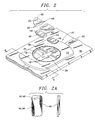
- FIG. 1 a top view of the embodied snowboard binding assembly 10 is shown with certain edges in phantom for clarity.
- the binding platform 12 has a circular cutout 14 in its relative center which has radially oriented teeth 16 along its circumferential edge. In practice, each tooth is oriented approximately two degrees apart along the circumference of cutout 14. Cutout 14 additionally includes a lip 18 which runs along the inner circumferential edge and extends inward a width w.
- a set of four triangular-shaped quadrant sections 20 each have a corresponding tongue section 22 which is positioned over the lip 18.
- Each quadrant section 20 is then bolted to the board 26 via an attachment means 24 which includes a traditional insert and machine screw arrangement, or a hole is tapped into a retention plate formed inside the board and the quadrant section 20 is attached with a sheet metal screw.
- an attachment means 24 which includes a traditional insert and machine screw arrangement, or a hole is tapped into a retention plate formed inside the board and the quadrant section 20 is attached with a sheet metal screw.
- a relatively thin, yet strong stainless steel band 30 runs along the longitudinal length of the board 26 and under the center of mounted binding platform 12. This band 30 is designed to slide forwards and backwards along the longitudinal length of the board 26 as facilitated by an attachment lever, at one end of the binding (not shown, see Figure 3).
- the band 30 has two laterally extending tabs 32 and 34, and each tab has an upwardly projecting post 36 and 38.
- a pair of slidably mounted, toothed segments 44 and 46 interact with the posts 36, 38 via angled receiving slots 40 and 42.
- Each segment 44, 46 is slidably mounted via rails 48 located on either side surface of the segments 44, 46. These rails 48 are received by a corresponding track 49 (see Figure 2) in each quadrant section 20.
- each quadrant section 20 is bolted to the board 26
- the sections 44, 46 are also slidably attached to the board, with the slots 40 and 42 receivably engaging the posts 36, 38.
- the quadrant sections 20 are also mounted on either side of band 30 as a guide down the center of the board.
- the forward and backward movement of the band 30 causes the posts 36, 38 to engage the angled slots 40, 42.
- the toothed sections 44, 46 slide inward and disengage from the circumferential teeth 16. This allows the binding platform 12 to freely rotate.
- the band 30 is slid backwards which causes the sections 44, 46 to slide outwards.
- the radial, outwardly facing teeth on sections 44, 46 then re-engage the circumferential teeth 16 on the binding platform, thereby locking the assembly in place.
- FIG 2 a pictorial view of the binding assembly 10 is shown with certain parts displayed in exploded fashion.
- the binding platform 12 is rotatably mounted on board 26 via attachment with quadrant sections 20.
- the tongue 22 shown to fit over circular lip 18, while the track 49 receivably engages the rail 48 on each side of the quadrant section 20.
- the angled slots 40, 42 are shown to receivably fit over posts 36, 38.
- Figure 2A shows a front and side view of the slidable toothed sections 44, 46 with the rails 48. Attachment of sections 20 also slidably secures sections 44, 46 to the assembly 10.
- lever 50 This lever might include any means capable of slidably controlling and locking the band 30, with the embodied levers being of the "over center” type.
- lever 50 must be actuated as shown by arrows 54 for the band 30 to move fore or aft. Also, the lever must be locked when the assembly is properly positioned.
- FIG 4 a cross sectional view of the snowboard 26 and binding assembly 10 are shown along cut 4-4 of Figure 2.
- the steel band 30 runs underneath the binding platform 12.
- the binding platform 12 is securely mounted to board 26 as described above, yet retains enough play to rotate over the surface of the board 26 and the underlying band 30.
- the band 30 is also held and guided by the binding assembly parts 10, yet remains free to slidably move fore and aft to thereby adjust the angle of the binding platform 12.
- Adjustable stops could also be included so that desired angles could conveniently be located and locked in with repeatability by the user.
- a thin, flexible plastic covering can be installed over the top of the assembly to protect it from snow and damage from the user's boot.
- Construction of the longitudinal band would include a stamp cut from a thin stainless steel sheet.
- the remaining assembly parts including the quadrant sections 20, the platform 12 and the toothed sections 44, 46 would be constructed of high strength plastic.
- the assembly parts 10 form a rotatable mechanism which is adjustable without the need for external tools, but which presents a height h between the boot and board which is comparable to presently used, conventional bindings. Bindings such as ROSSIGNOL for instance have a height h of approximately less than 1.27 cm (0.5 inches).
- the binding assembly 10 is also symmetrical and can be mounted for either left or right facing stances.
- FIG. 5 shows yet another embodiment of the snowboard binding assembly 60.
- the binding platform 62 is paddle-shaped with a central portion 64 and a neck 66.
- a boot mounting fixture 63 rotatably rests on top of the binding platform 62.
- the binding platform 62 and mounting fixture 63 are typically formed of durable, high impact plastic.
- a circular insert 68 is fitted in the mounting fixture 63 for receiving a toothed ring insert 70.
- the insert 68 and ring 70 are formed from metal in the preferred embodiment, but might be formed from other such durable materials.
- a circular cutout area 69 is formed in the mounting fixture 63 through to the binding platform 62 below.
- a central anchoring insert 72 is used to slidably anchor the mounting fixture 63 to the assembly platform 62, which is then mounted onto the underlying snowboard (not shown).
- the anchoring insert 72 includes a central channel 74 for receiving a pair of slidably mounted, toothed segments 76 and 78.
- the toothed segments each have oblong through holes 77 and 79 for receiving posts 80 and 82 which extend upward from the top surface of a steel band 84 which runs underneath the assembly (See Figure 6, described below).
- a pair of holes 81 and 83 extend through the anchoring insert 72 to allow the posts 80, 82 to extend upwards into the holes 77, 79.
- the toothed segments 76, 78 each have rails 86 which extend from each side of the segments.
- the rails operatively interact with a groove 88 which is formed in either side of the channel 74.
- the segments 76, 78 are then slidably mounted in the anchoring insert 72 by sliding the segments 76, 78 into either end of the channel 74 with the rails 86 slidably fitting into the grooves 88.
- the anchoring insert 72 also has an outer diameter 73 which is slightly larger than the inner diameter 71 of the circular insert 68.
- a series of four mounting holes 90 in the anchoring insert 72 are aligned with a corresponding set of four holes 94 in the assembly platform 62.
- Various mounting devices might be used through the holes including screws, rivets, or nut and bolt combinations for attaching the anchoring insert 72 to the assembly platform 62.
- the toothed ring 70 has a thickness 100 and an inner diameter 98 with a toothed inner surface 96 facing inwards.
- the edges 102 and 104 of the ring 70 are cut off to facilitate mounting of the ring 70 in the boot mounting fixture 63 along edges 106 and 108.
- a series of four attachment holes 142 in the ring 70 align with corresponding attachment holes 144 in the circular insert 68 for attaching the ring 70 to the insert 68.
- the bottom 120 of the mounting assembly platform 62 includes a T-shaped stainless steel strap 122 running in a channel 123 along the longitudinal length of the platform 62 and along the neck portion 66.
- the strap 122 is attached at the neck portion via a connector 126 to a handle or lever 124 which slidably interacts with the neck portion 66 of the platform 62.
- the opposite T-shaped portion 128 of the strap 122 includes a first and second tab 130 and 132.
- the posts 80 and 82 are respectively mounted via connectors 131 and 133 to the top surface 84 of the steel band 122.
- the posts 80 and 82 extend upward through holes 134 and 136 formed in the assembly platform 62.
- the holes 134, 136 are further surrounded by a indentation 135 approximately the thickness of the strap 122 and the channel 123.
- a indentation 135 approximately the thickness of the strap 122 and the channel 123.
- the toothed segments 76 and 78 are slidably inserted into the channel 74 so that the rails 86 and grooves 88 appropriately interfit.
- the strap 122 and lever/handle 124 are slidably attached onto the bottom 120 of the assembly platform 62 so that the posts 80 and 82 extend upwards through holes 134 and 136.
- the anchoring insert 72 is then placed over the cutout section 69 in the boot mounting fixture 63, with the holes 81, 83 and oblong cutouts 77, 79 aligned so that the posts 80 and 82 extend through the respective openings.
- the anchoring insert 72 is attached to the assembly platform 62 via an attachment device being inserted through mounting holes 90 and 94.
- the toothed ring component 70 is next placed over the anchoring insert 72 so that the central portion 140 encircles the upper portion of the insert 72, with the inner diameter 98 of ring 70 being slightly larger than the outer diameter 73 of the anchoring insert 72.
- the handle 124 can be moved to slide the bar 122.
- the posts 80, 82 will thereby move backwards or forwards inside the oblong slots 77, 79 to cause the toothed segments 76, 78 to move inwards and outwards.
- the segments 76, 78 are slidably pushed outwards so that the teeth sections 92 and 93 engage the teeth 96 along the inner diameter of the ring 70.
- the segments 76, 78 are slidably pulled inwards via movement of the posts 80, 82.
- the teeth surfaces 92, 93 and 96 are disengaged and the boot mounting fixture 63 can be freely rotated to a new position.
- FIG. 7 a top view of the binding assembly 60 is shown, in an assembled condition.
- the boot mounting fixture 63 is shown positioned on top of the assembly platform 62 and includes a rear boot support 150 and a buckle device 152 and a strap 153. The ski boot is thereby placed in the mounting fixture 63 and strapped in place.
- the anchoring insert 72 is shown secured to the platform 62 through connectors 138 placed through the mounting holes 90.
- the toothed segments 76, 78 slidably engage the toothed surface 96 on the ring 70, and include springs 154 attached between the sliding segments 76, 78.
- the springs 154 provide outward force to push the segments 76, 78 towards a lockably engaged position.
- the handle 124 can also be spring loaded internally to create a default locked position which must be overcome with sufficient backward pressure on the handle 124.
- cover plates 160 and 162 are shown which are used to cover and protect the assembled components from contact with the user's boot, as well as snow, ice, and dirt.
- the cover plates might be formed from durable plastic or metal and can be attached via external attachment devices.
- the preferred embodiment uses tabs or extensions formed in the plates which frictionally interact with the underlying binding assembly.
Landscapes
- Footwear And Its Accessory, Manufacturing Method And Apparatuses (AREA)
- Materials Applied To Surfaces To Minimize Adherence Of Mist Or Water (AREA)
- Suspension Of Electric Lines Or Cables (AREA)
- Bridges Or Land Bridges (AREA)
- Buildings Adapted To Withstand Abnormal External Influences (AREA)
- Cleaning Of Streets, Tracks, Or Beaches (AREA)
- Steering Devices For Bicycles And Motorcycles (AREA)
- Clamps And Clips (AREA)
- Sealing Devices (AREA)
Abstract
Description
- This invention relates to a snowboard binding mechanism which can be conveniently rotated and locked at any angle relative to the board without removing the boot from the binding and without the need for external tools.
- Snowboarding is a relatively new sport which can be visually compared to skateboarding and surfing, except its done on snow. Snowboard skiing is the legal name for snowboarding, which thereby affords snowboarding all the privileges and liabilities of alpine skiing. To snowboard, the rider stands on the board with his/her left or right foot forward, facing one side of the board. The feet are attached to the board via high-back or plate bindings which are non-releasable. Although there is at least one manufacturer of releasable bindings, they are not widely used. Moreover, the sport is distinct from monoskiing, wherein both feet are side by side on a single ski and the skier faces forward.
- Snowboarding has gained in popularity only during the last 10 years. It was pioneered in the late 1970's by a small group of individuals with credit going to Jake Burton and Tom Sims. Both individuals now head snowboard manufacturers, with Burton being the largest snowboard manufacturer in the world. Burton has been frequently attributed with credit for having developed the first high-back bindings and metal edged boards. The roots, however, really started with the "snurfer" which was a sledding toy shaped like a small water ski, with rope tied to the nose and a rough surface for traction running from the center to the back where the user stood. Burton was involved with snurfer racing and was the first to put a foot retention device on his boards. Accordingly, Burton and his boards began to regularly win these events and an industry was born. Today there are more than 65 snowboard equipment manufacturers of boards, boots, and bindings. The cost of snowboard equipment is very comparable to ski equipment with a wide range of costs and types.
- Snowboarding is now prevalent on virtually all downhill ski slopes worldwide. In 1985 only 7 percent of ski areas allowed snowboards; today more than 90 percent allow snowboards, and over half have specialized snowboard areas referred to as half pipes. A half pipe is a trough cut or built up with snow, with the term originating from skateboarding. Today about 10 percent of the world skier population consists of snowboarders, with the annual growth rate for the sport projected at 20 percent. In the United States, about 80 percent of snowboarders are male with an average age of 20.8 years. The average snowboarder rides 15 days a year which is 3 times that of the average skier. The PSIA (Professional Ski Instructors of America) and CSF (Canadian Snowboard Federation) now certifies snowboard instructors and most resorts which allow boarding will have instructors on staff. Moreover, the National Ski Patrol (NSP) and Canadian Ski Patrol (CSP) are actively integrating snowboards into their rescue programs.
- Accordingly, major competitions utilizing snowboarding equipment are continually being organized involving major sponsorships, television coverage, and world-class athletes with snowboarding also soon to be an Olympic event. Such competitions range from downhill speed runs to slalom races to half-pipe and freestyle performances. As a result, four major categories of boards have been developed including race, alpine, all-around/free-riding, and half-pipe/freestyle.
- Two types of bindings are commonly used in snowboarding: the high-back and the plate. The high-back is characterized by a vertical plastic back piece which is used to apply pressure to the heel-side of the board. This binding has two straps which go over the foot, with one strap holding down the heel and the other holding down the toe. Some high-backs also have a third strap on the vertical back piece called a shin strap which gives additional support and aids in toe side turns. The plate, or step-in binding, is used with a hard shell boot much like a ski binding except it is non-releasable.
- For different events, the desired angle of the binding relative to the longitudinal axis of the board might need to be changed. For instance, during speed runs such as Giant Slalom (GS) the snowboarder would prefer to have his feet oriented more relatively straight ahead. For other events such as freestyle, the desired angle would be oriented more perpendicular to the longitudinal axis. From Transworld Snowboarding the average stances of pro riders from different snowboarding disciplines are as follows with width in centimetres (inches), angles in degrees with 0 degrees being perpendicular to the longitudinal axis, center being inches back from center, and length in cm:
stance width front angle rear angle center board length Half-pipe: 52.6 (20.7) 17 2 1.3 (0.5) 152.5 Freeride: 53.6 (21.1) 22 7 4.3 (1.7) 170 Slalom: 43.2 (17) 49.2 47.2 1.0 (0.4) 156.8 GS 43.2 (17) 49.6 47.6 1.1 (0.44) 164.9 Super G 43.2 (17.16) 49.4 47.4 1.1 (0.45) 170.5 SlopeStyle 54.1 (21.3) 12 0 2.5 (1) 152.9 - Presently, snowboard bindings cannot be rotated and locked at different angular positions without using external tools. Bindings use either inserts or retention plate securement methods. Inserts consist of a nut built into the board with a machine screw then used to secure the binding. With the retention plate system, a sheet metal screw is used after tapping a hole into the board. It is referred to as plate retention because a metal plate is built into the board where the board will be tapped. The two most popular binding hole patterns include the Burton 3D and the F2 4X4. Each pattern provides 4 different positions or settings for stance adjustment of each binding. The majority of non-Burton boards use the 4X4 pattern.
- However, with each securement and hole pattern method the user must first remove the boot from the binding and then loosen the series of screws -- typically with a screwdriver -- so the binding can be rotated and positioned at the desired angle. The loose screws must be retightened to lock the binding in place and the user can then reinsert the boot into the binding. Such an operation is difficult, time consuming, and inconvenient for the snowboarder. It would be impractical to require a snowboarder to perform such a field operation on their snowboard. This is particularly true given the high cost of ski-lift tickets and the overall desire by riders to maximize the number of runs performed during any given day.
- Most people who use snowboards recreationally prefer to have their front foot positioned at a large angle (e.g. approximately 45 degrees or more) with respect to the longitudinal axis of the snowboard. After snowboarding down the slope, the user typically releases their rear boot and pushes along with the free foot to move the snowboard. Such action is similar to that provided by a skateboarder to move forward on flat surfaces, and hence is called "skating." If enough speed can be achieved via skating, the snowboarder can "glide" by placing the rear foot on the stomp pad which is attached between the bindings where the rear foot can be set when it is not in the rear binding. However, unlike skateboarding where both feet are free, the snowboarder's front foot is fixed at an awkward and inconvenient angle thereby making it difficult to achieve efficient forward locomotion.
- Additionally, the inconvenient angle of the user's foot poses a problem when the snowboarder boards and dismounts the ski lift. When sitting down and extending the legs forward, the angle of the mounted foot causes the snowboard to interfere with adjacent passengers on the ski lift. This causes the snowboarder to uncomfortably twist their foot and/or leg and/or body sideways to compensate for the angle of the snowboard. This is particularly unacceptable in light of the long ride time of 15 minutes or more found on most ski lifts. Moreover, such twisting and contorting by the snowboarder might increase the chance of passengers or equipment falling from the lift.
- Not only is this situation dangerous and annoying for fellow passengers on the ride up, it is also dangerous upon reaching the disembarkment point on the lift. Due to the unnatural orientation of the snowboarder's mounted foot, it may be difficult for the snowboarder to dismount the lift along the typical straight and narrow path found at most unloading points. Any deviation or lack of control can cause the snowboarder to careen into other patrons, and/or into dangerous obstacles like lift equipment. Moreover, if the snowboarder falls into the path of other disembarking patrons, the whole lift must be stopped until the snowboarder can collect himself and move out of danger.
- FR-A-2627097 discloses a snowboard boot mounting that is rotatable to allow a user to change the angle of their feet in relation to the board. To operate the binding to change this angle, the user must first remove their boot from the snowboard binding.
- Accordingly, a snowboard binding is needed wherein the mounting angle relative to the longitudinal axis of the board can be easily adjusted, through any angle, without the need for external tools or removal of the mounted boot from the binding. This will allow the snowboarder to adjust his foot for different angles for making runs under different conditions. Such a binding will also allow the snowboarder to quickly adjust his mounted foot to a forward facing angle at the end of a run. This will thereby facilitate more efficient and controllable forward locomotion through skating and gliding motions, and also eliminate interference of the snowboard with adjacent fellow passengers on ski lifts.
- Accordingly, it is an object of the present invention to provide a snowboard binding which can be rotatably adjusted without removing the mounted boot and without the use of external tools.
- It is yet another object of the present invention to provide a snowboard binding which utilizes a slidable bar actuated by a single or dual lever/handle which pivots or slides for controlling the releasable rotation of the binding platform.
- It is still another object of the present invention to provide a snowboard binding which utilizes a circular cutout with radially oriented teeth for engaging and disengaging toothed segments which slide in connectable conjunction with the slidable bar.
- It is a further object of the present invention to provide a snowboard binding which utilizes a set of quadrant attachment pieces for attaching the rotatable platform to the board.
- It is yet another object of the present invention to provide a series of adjustable stops to conveniently position the binding at predetermined angles.
- It is still a further object of the present invention to provide an adjustable binding which is comparable in height to present bindings.
- Yet another object of the present invention is to provide a protective plastic covering over the mechanism to protect it from snow.
- Accordingly, in a first aspect, the invention consists in an adjustable snowboard binding assembly which can be rotated and fixed at chosen orientation angles with respect to a snowboard without the use of external tools and includes a mounting assembly platform with attachment holes, the mounting assembly having a longitudinal length with a central portion and a neck portion;
a rotatable boot mounting fixture with a central cutout and a circular insert having a first inner diameter;
a pair of side segments having guide rails extending laterally along their sides, each having an angled receiving slot, and an outwardly facing toothed edge;
an anchoring insert with a second outer diameter which overlaps said first inner diameter of said circular insert, said anchoring insert having a lateral channel for receiving said side segments and said guide rails, and a plurality of attachment holes for receiving an attachment means;
a toothed ring insert with a third inner diameter which encompasses said second outer diameter of said anchoring insert and having a plurality of radially oriented circumferential teeth along its inwardly facing circumference, and being attached via the attachment holes and the attachment means to said circular insert;
characterised by a slidable band positioned adjacent to the side of the mounting assembly platform which is in use adapted to be positioned adjacent to the snowboard and extending along said longitudinal length of the platform with a pair of laterally extending side tabs, each side tab having an upwardly extending post;
wherein said attachment means attaches said anchoring insert to said mounting assembly platform via said attachment holes so that said boot mounting fixture is rotatably held in the binding assembly by the anchoring insert, and said side segments are slidably held in said anchoring insert via said interfacing rail and channel, and said posts are received in said angled slots via through holes provided in said lateral channel and thereby control the lateral sliding movement of said side segments in response to movement of said slidable band so that said teeth on said side segments are selectively engaged or disengaged with said teeth on said toothed ring insert. - In a second aspect, the invention consists in an adjustable snowboard binding assembly which can be rotated and locked to a mounting assembly platform of a snowboard at chosen orientation angles without the use of external tools and includes a boot mounting fixture rotatably attached by mounting means to said platform and including a centralised circular cutout having a plurality of radially oriented inwardly facing circumferential teeth; and
at least two radially sliding segments for engagement with said circumferential teeth;
characterised by a slidable band positioned adjacent the surface of the boot mounting fixture which, in use, is adapted to be positioned adjacent to the mounting assembly platform of the snowboard, said sliding segments being releasably engageable with said circumferential teeth via actuating means attached to said slidable band;
wherein from a locked position, said actuating means releases said sliding segments which slidably disengage said circumferential teeth on said boot mounting fixture thereby allowing rotation of said boot mounting fixture to a new position, with said actuating means then being used to slidably re-engage said teeth to lock said boot mounting fixture into place. - The present invention teaches a snowboard binding that can be conveniently rotated and locked at any angle without removing the boot from the binding and without the need for external adjustment tools. The embodied invention uses a stainless steel band which runs along the longitudinal axis of the snowboard and which can be moved fore and aft via a lever located at each end of the band. Alternatively, a single slidable lever or handle can be used on one end of the stainless steel band, whereby the band would run along the longitudinal axis from the lever or handle to the center of the binding mechanism. The binding platform contains a circular cutout with radial, inwardly facing teeth along the outer circumference of the cutout. A pair of toothed segments with outwardly facing radial teeth are connected to the slidable band so that they move outward to engage the teeth on the cutout circumference. The toothed segments are held in place by adjacent quadrant segments which are bolted to the board, and which in turn hold the rotatable platform onto the board.
- Under these arrangements, the mounted foot can be rotated through any angle by the user without having to remove the boot and loosen any screws. Instead, the single or dual lever or handle means are actuated and the band is slid forwards or backwards to slidably disengage the toothed segments from the circumferential teeth on the cutout. The binding platform can then be rotated to any angle and be locked into position by reactuating the lever and sliding the band to cause slidable engagement between the toothed segments and cutout teeth.
- Other objects and advantages of this invention will become apparent from the following description taken in conjunction with the accompanying drawings wherein are set forth, by way of illustration and example, certain embodiments of this invention. The drawings constitute a part of this specification and include exemplary embodiments of the present invention and illustrate various objects and features thereof.
-
- Figure 1 shows a top view of the rotatable binding assembly.
- Figure 2 shows a perspective, partially exploded view of the rotatably binding assembly.
- Figure 2A shows a top and side view of the sliding toothed section of Figure 2.
- Figure 3 shows a side view of the snowboard, with the center binding assembly excluded, which shows the sliding center bar and release levers.
- Figure 4 shows a cross-sectional view of the snowboard and binding assembly along cut 4-4 of Figure 2.
- Figure 5 shows a perspective, partially exploded view of an alternative rotatable binding assembly with a sliding lever handle at one end.
- Figure 6 shows a bottom view of the binding assembly of Figure 5.
- Figure 7 shows a top view of the binding assembly of Figure 5 with a boot clamping mechanism further mounted on top.
- Figure 8 shows a protective plate which is mounted over the top of the binding mechanism.
- Figure 9 shows a protective plate which is mounted over the top of the binding mechanism.
-
- Referring now to Figure 1, a top view of the embodied
snowboard binding assembly 10 is shown with certain edges in phantom for clarity. The bindingplatform 12 has acircular cutout 14 in its relative center which has radially orientedteeth 16 along its circumferential edge. In practice, each tooth is oriented approximately two degrees apart along the circumference ofcutout 14.Cutout 14 additionally includes alip 18 which runs along the inner circumferential edge and extends inward a width w. A set of four triangular-shapedquadrant sections 20 each have acorresponding tongue section 22 which is positioned over thelip 18. Eachquadrant section 20 is then bolted to theboard 26 via an attachment means 24 which includes a traditional insert and machine screw arrangement, or a hole is tapped into a retention plate formed inside the board and thequadrant section 20 is attached with a sheet metal screw. With thecircular lip 18 andtongue 22 arrangement between the bindingplatform 12 and eachquadrant section 20, theplatform 12 is free to rotate through 360 degrees as shown byarrows 13 and yet remain secured to the board. - A relatively thin, yet strong
stainless steel band 30 runs along the longitudinal length of theboard 26 and under the center of mounted bindingplatform 12. Thisband 30 is designed to slide forwards and backwards along the longitudinal length of theboard 26 as facilitated by an attachment lever, at one end of the binding (not shown, see Figure 3). Theband 30 has two laterally extendingtabs post toothed segments posts slots segment rails 48 located on either side surface of thesegments rails 48 are received by a corresponding track 49 (see Figure 2) in eachquadrant section 20. Hence, as eachquadrant section 20 is bolted to theboard 26, thesections slots posts quadrant sections 20 are also mounted on either side ofband 30 as a guide down the center of the board. - In operation, the forward and backward movement of the
band 30 causes theposts angled slots band 30 is moved forward, thetoothed sections circumferential teeth 16. This allows the bindingplatform 12 to freely rotate. When theplatform 12 is in its desired position, theband 30 is slid backwards which causes thesections sections circumferential teeth 16 on the binding platform, thereby locking the assembly in place. - Referring now to Figure 2, a pictorial view of the binding
assembly 10 is shown with certain parts displayed in exploded fashion. As detailed above, the bindingplatform 12 is rotatably mounted onboard 26 via attachment withquadrant sections 20. Thetongue 22 shown to fit overcircular lip 18, while thetrack 49 receivably engages therail 48 on each side of thequadrant section 20. Theangled slots posts platform 12 is free to rotate when thesections teeth 16. Figure 2A shows a front and side view of the slidabletoothed sections rails 48. Attachment ofsections 20 also slidably securessections assembly 10. - Referring now to Figure 3, a side view of the
board 26 is shown with the center section omitted. Thestainless steel band 30 runs along the top and is slidably controlled by alever 50. This lever might include any means capable of slidably controlling and locking theband 30, with the embodied levers being of the "over center" type. Hence,lever 50 must be actuated as shown byarrows 54 for theband 30 to move fore or aft. Also, the lever must be locked when the assembly is properly positioned. - Referring now to Figure 4, a cross sectional view of the
snowboard 26 and bindingassembly 10 are shown along cut 4-4 of Figure 2. As shown, thesteel band 30 runs underneath the bindingplatform 12. The bindingplatform 12 is securely mounted to board 26 as described above, yet retains enough play to rotate over the surface of theboard 26 and theunderlying band 30. Theband 30 is also held and guided by the bindingassembly parts 10, yet remains free to slidably move fore and aft to thereby adjust the angle of the bindingplatform 12. Adjustable stops could also be included so that desired angles could conveniently be located and locked in with repeatability by the user. - Furthermore, a thin, flexible plastic covering can be installed over the top of the assembly to protect it from snow and damage from the user's boot. Construction of the longitudinal band would include a stamp cut from a thin stainless steel sheet. The remaining assembly parts including the
quadrant sections 20, theplatform 12 and thetoothed sections assembly parts 10 form a rotatable mechanism which is adjustable without the need for external tools, but which presents a height h between the boot and board which is comparable to presently used, conventional bindings. Bindings such as ROSSIGNOL for instance have a height h of approximately less than 1.27 cm (0.5 inches). The bindingassembly 10 is also symmetrical and can be mounted for either left or right facing stances. - Figure 5 shows yet another embodiment of the
snowboard binding assembly 60. In this embodiment, the bindingplatform 62 is paddle-shaped with acentral portion 64 and aneck 66. Aboot mounting fixture 63 rotatably rests on top of the bindingplatform 62. The bindingplatform 62 and mountingfixture 63 are typically formed of durable, high impact plastic. Acircular insert 68 is fitted in the mountingfixture 63 for receiving atoothed ring insert 70. Theinsert 68 andring 70 are formed from metal in the preferred embodiment, but might be formed from other such durable materials. Acircular cutout area 69 is formed in the mountingfixture 63 through to the bindingplatform 62 below. Acentral anchoring insert 72 is used to slidably anchor the mountingfixture 63 to theassembly platform 62, which is then mounted onto the underlying snowboard (not shown). - The anchoring
insert 72 includes acentral channel 74 for receiving a pair of slidably mounted,toothed segments holes posts steel band 84 which runs underneath the assembly (See Figure 6, described below). A pair ofholes 81 and 83 extend through the anchoringinsert 72 to allow theposts holes - The
toothed segments groove 88 which is formed in either side of thechannel 74. Thesegments insert 72 by sliding thesegments channel 74 with therails 86 slidably fitting into thegrooves 88. - The anchoring
insert 72 also has anouter diameter 73 which is slightly larger than theinner diameter 71 of thecircular insert 68. A series of four mountingholes 90 in the anchoringinsert 72 are aligned with a corresponding set of fourholes 94 in theassembly platform 62. Various mounting devices might be used through the holes including screws, rivets, or nut and bolt combinations for attaching the anchoringinsert 72 to theassembly platform 62. When the outerdiametric edge 73 of the anchoringinsert 72 is secured over thecircular insert 68 theboot mounting fixture 63 is thereby rotatably attached to theassembly platform 62. - The
toothed ring 70 has athickness 100 and aninner diameter 98 with a toothedinner surface 96 facing inwards. Theedges ring 70 are cut off to facilitate mounting of thering 70 in theboot mounting fixture 63 alongedges 106 and 108. A series of fourattachment holes 142 in thering 70 align with corresponding attachment holes 144 in thecircular insert 68 for attaching thering 70 to theinsert 68. - Referring also to Figure 6, the bottom of the binding
assembly 60 is shown. Thebottom 120 of the mountingassembly platform 62 includes a T-shapedstainless steel strap 122 running in achannel 123 along the longitudinal length of theplatform 62 and along theneck portion 66. Thestrap 122 is attached at the neck portion via aconnector 126 to a handle or lever 124 which slidably interacts with theneck portion 66 of theplatform 62. The opposite T-shaped portion 128 of thestrap 122 includes a first andsecond tab posts connectors top surface 84 of thesteel band 122. Theposts holes assembly platform 62. Theholes indentation 135 approximately the thickness of thestrap 122 and thechannel 123. By embedding thestrap 122 in such achannel 123, the bottom of the bindingassembly 60 can mount flush against the upper surface of the snowboard.Connectors 138 are also shown which connect theassembly platform 62 to the anchoringinsert 72. - To operably assemble the parts of the binding
assembly 60, thetoothed segments channel 74 so that therails 86 andgrooves 88 appropriately interfit. Thestrap 122 and lever/handle 124 are slidably attached onto thebottom 120 of theassembly platform 62 so that theposts holes insert 72 is then placed over thecutout section 69 in theboot mounting fixture 63, with theholes 81, 83 andoblong cutouts posts insert 72 is attached to theassembly platform 62 via an attachment device being inserted through mountingholes toothed ring component 70 is next placed over the anchoringinsert 72 so that thecentral portion 140 encircles the upper portion of theinsert 72, with theinner diameter 98 ofring 70 being slightly larger than theouter diameter 73 of the anchoringinsert 72. In this configuration, thehandle 124 can be moved to slide thebar 122. Theposts oblong slots toothed segments bar 122 is extended to its foremost point, thesegments teeth sections teeth 96 along the inner diameter of thering 70. Conversely, when thebar 122 is moved backwards, thesegments posts boot mounting fixture 63 can be freely rotated to a new position. - Referring now to Figure 7, a top view of the binding
assembly 60 is shown, in an assembled condition. Theboot mounting fixture 63 is shown positioned on top of theassembly platform 62 and includes arear boot support 150 and abuckle device 152 and astrap 153. The ski boot is thereby placed in the mountingfixture 63 and strapped in place. The anchoringinsert 72 is shown secured to theplatform 62 throughconnectors 138 placed through the mounting holes 90. Thetoothed segments toothed surface 96 on thering 70, and includesprings 154 attached between the slidingsegments springs 154 provide outward force to push thesegments handle 124 can also be spring loaded internally to create a default locked position which must be overcome with sufficient backward pressure on thehandle 124. - Referring also Figures 8 and 9, different embodiments of
cover plates
Claims (14)
- An adjustable snowboard binding assembly (60) which can be rotated and fixed at chosen orientation angles with respect to a snowboard without the use of external tools and includes a mounting assembly platform (62) with attachment holes (94), the mounting assembly having a longitudinal length with a central portion (64) and a neck portion (66);
a rotatable boot mounting fixture (63) with a central cutout (69) and a circular insert (68) having a first inner diameter;
a pair of side segments (76,78) having guide rails (86) extending laterally along their sides, each having an angled receiving slot (77,79), and an outwardly facing toothed edge;
an anchoring insert (72) with a second outer diameter which overlaps said first inner diameter of said circular insert (68), said anchoring insert having a lateral channel (74) for receiving said side segments and said guide rails, and a plurality of attachment holes (90) for receiving an attachment means;
a toothed ring insert (70) with a third inner diameter which encompasses said second outer diameter of said anchoring insert (72) and having a plurality of radially oriented circumferential teeth (96) along its inwardly facing circumference, and being attached via the attachment holes (94) and the attachment means to said circular insert (68);
characterised by a slidable band (122) positioned adjacent to the side of the mounting assembly platform (62) which is in use adapted to be positioned adjacent to the snowboard and extending along said longitudinal length of the platform with a pair of laterally extending side tabs (130,132), each side tab having an upwardly extending post (80,82);
wherein said attachment means attaches said anchoring insert (72) to said mounting assembly platform (62) via said attachment holes (90,94) so that said boot mounting fixture (63) is rotatably held in the binding assembly by the anchoring insert (72), and said side segments are slidably held in said anchoring insert via said interfacing rail (88) and channel (74), and said posts (80,82) are received in said angled slots via through holes provided in said lateral channel (74) and thereby control the lateral sliding movement of said side segments in response to movement of said slidable band so that said teeth on said side segments are selectively engaged or disengaged with said teeth on said toothed ring insert. - The adjustable snowboard binding assembly of claim 1, wherein said slidable band (122) includes a slidable handle means (124) on said neck portion (66) of said mounting assembly platform (62) which is manually actuated to achieve slidable movement of said band.
- The adjustable snowboard binding assembly of claim 1 or claim 2, wherein said circumferential teeth (96) are oriented to provide one degree of resolution between adjacent fixing positions over 360 degrees of rotation.
- The adjustable snowboard binding assembly of any one of the preceding claims, wherein said mounting assembly platform (62), said boot mounting fixture (63) and said side segments (76,78) are constructed from high strength, cold resistant plastic.
- The adjustable snowboard binding assembly of any one of the preceding claims, wherein said slidable band (122) is stamped from stainless steel sheet metal.
- The adjustable snowboard binding assembly of any one of the preceding claims, wherein inserts are mounted in said mounting assembly platform (62) aligned with said attachment holes (94) and said attachment means comprise machine screws for attaching thereto.
- The adjustable snowboard binding assembly of any one of claims 1 to 5, wherein said attachment means includes attachment holes (94) in said mounting assembly platform (62) with accompanying nut and bolt means for attaching components thereto.
- The adjustable snowboard binding assembly of any one of the preceding claims, wherein a protective cover (160,162) is placed over the completed binding assembly.
- An adjustable snowboard binding assembly (10) which can be rotated and locked to a mounting assembly platform of a snowboard at chosen orientation angles without the use of external tools and includes a boot mounting fixture (12) rotatably attached by mounting means (20) to said platform (26) and including a centralised circular cutout (14) having a plurality of radially oriented inwardly facing circumferential teeth (16); and
at least two radially sliding segments (44,46) for engagement with said circumferential teeth;
characterised by a slidable band (30) positioned adjacent the surface of the boot mounting fixture (12) which, in use, is adapted to be positioned adjacent to the mounting assembly platform of the snowboard, said sliding segments being releasably engageable with said circumferential teeth via actuating means (36,38) attached to said slidable band;
wherein from a locked position, said actuating means (36,38) releases said sliding segments (44,46) which slidably disengage said circumferential teeth on said boot mounting fixture (12) thereby allowing rotation of said boot mounting fixture (12) to a new position, with said actuating means then being used to slidably re-engage said teeth to lock said boot mounting fixture into place. - The adjustable snowboard binding assembly of claim 9, wherein said radially sliding segments (44,46) each include guide rails (48) extending laterally along their sides, an angled receiving slot (40,42), and an outwardly facing toothed edge for engagement with said circumferential teeth.
- The adjustable snowboard binding assembly of claim 9 or claim 10, wherein said mounting means includes at least one anchoring insert (20) which overlaps said circular cutout (14) in said boot mounting fixture, and at least one attachment hole (24) provided for an attachment means to connect said anchoring insert to said mounting assembly platform (20) of said snowboard.
- The adjustable snowboard binding assembly of any one of claims 9 to 11, wherein said slidable band (30) extends along the longitudinal length of the snowboard with a pair of laterally extending side tabs (32,34), each side tab having an upwardly extending post (36,38) which is received by an angled receiving slot (40,42) of a respective side segment, whereby fore and aft movement of said band causes radial sliding of said side segments.
- The adjustable snowboard binding assembly of any one of claims 9 to 12, wherein said plurality of circumferential teeth (16) are oriented to provide one degree of resolution between adjacent fixing positions over 360 degrees of rotation.
- The adjustable snowboard binding assembly of claim 9, wherein a protective cover (160, 162) is placed over the completed binding assembly.
Applications Claiming Priority (3)
| Application Number | Priority Date | Filing Date | Title |
|---|---|---|---|
| US08/615,683 US5584492A (en) | 1996-03-13 | 1996-03-13 | Snowboard binding mechanism |
| US615683 | 1996-03-13 | ||
| PCT/US1996/019789 WO1997033664A1 (en) | 1996-03-13 | 1996-12-17 | Snowboard binding mechanism |
Publications (3)
| Publication Number | Publication Date |
|---|---|
| EP0956112A4 EP0956112A4 (en) | 1999-11-17 |
| EP0956112A1 EP0956112A1 (en) | 1999-11-17 |
| EP0956112B1 true EP0956112B1 (en) | 2002-09-04 |
Family
ID=24466417
Family Applications (1)
| Application Number | Title | Priority Date | Filing Date |
|---|---|---|---|
| EP96944331A Expired - Lifetime EP0956112B1 (en) | 1996-03-13 | 1996-12-17 | Snowboard binding mechanism |
Country Status (8)
| Country | Link |
|---|---|
| US (2) | US5584492A (en) |
| EP (1) | EP0956112B1 (en) |
| JP (1) | JP2000506411A (en) |
| AT (1) | ATE223247T1 (en) |
| DE (1) | DE69623506T2 (en) |
| DK (1) | DK0956112T3 (en) |
| ES (1) | ES2183027T3 (en) |
| WO (1) | WO1997033664A1 (en) |
Cited By (1)
| Publication number | Priority date | Publication date | Assignee | Title |
|---|---|---|---|---|
| EP2745887A1 (en) * | 2012-12-20 | 2014-06-25 | Salomon S.A.S. | Boot binding on sports equipment |
Families Citing this family (63)
| Publication number | Priority date | Publication date | Assignee | Title |
|---|---|---|---|---|
| US5984325A (en) * | 1995-12-04 | 1999-11-16 | Acuna; Peter R. | Angularly adjustable snowboard boot binding |
| US6105996A (en) * | 1995-12-19 | 2000-08-22 | Emery S.A. | Shoe and binding of snowboard assembly |
| US5810370A (en) * | 1996-03-04 | 1998-09-22 | Covert; Richard P. | Snow board binding |
| US5868416A (en) * | 1996-03-13 | 1999-02-09 | Fardie; Kenneth W. | Adjustable release mechanism for rotating bindings |
| US5816590A (en) * | 1997-04-02 | 1998-10-06 | Uniboard Corporation | Nordic skiboard |
| IT1288636B1 (en) * | 1996-07-05 | 1998-09-23 | Nordica Spa | ANGULAR ADJUSTMENT DEVICE PARTICULARLY FOR A SNOWBOARD BINDING |
| IT1288654B1 (en) * | 1996-09-04 | 1998-09-23 | Adriano Girotto | ATTACK FOR SNOWBOARD WITH LOCKING BY ROTATION |
| FR2755029B1 (en) * | 1996-10-25 | 1999-01-15 | Salomon Sa | DEVICE FOR ADJUSTING THE POSITION OF A FIXATION ON A SNOWBOARD, IN PARTICULAR SNOW SURFING |
| US5890729A (en) * | 1996-12-05 | 1999-04-06 | Items International, Inc. | Rotatably adjustable snowboard binding assembly |
| US6648365B1 (en) | 1997-01-08 | 2003-11-18 | The Burton Corporation | Snowboard binding |
| US6029991A (en) * | 1997-03-13 | 2000-02-29 | Frey; Bernard M. | Impact releasable snowboard boot binding assembly and method |
| US6786502B2 (en) * | 1997-07-28 | 2004-09-07 | Stephen R. Carlson | Longitudinally adjustable mount for a snowboard binding |
| US6015161A (en) * | 1997-07-28 | 2000-01-18 | Carlson; Stephen R. | Longitudinally adjustable mount for a snowboard binding |
| US6189899B1 (en) * | 1997-07-28 | 2001-02-20 | Stephen R. Carlson | Longitudinally adjustable mount for a snowboard binding |
| ATE229362T1 (en) | 1997-10-28 | 2002-12-15 | Emery Sa | SKI BOOT BINDING SYSTEM FOR SNOWBOARD |
| US6467794B1 (en) | 1997-11-19 | 2002-10-22 | Emery S.A. | Device for fixing a shell for maintaining a boot of a snow surf board |
| US5967542A (en) * | 1997-11-25 | 1999-10-19 | Sims Sports, Inc. | Mounting disk and base for snowboard binding |
| US6189913B1 (en) | 1997-12-18 | 2001-02-20 | K-2 Corporation | Step-in snowboard binding and boot therefor |
| WO1999048573A2 (en) * | 1998-03-23 | 1999-09-30 | Sabol Jeffrey P | Double lock rotatable snowboard boot binding |
| US6155578A (en) * | 1998-04-21 | 2000-12-05 | Patterson; Patrick J. | Binding mount |
| US6102430A (en) * | 1998-05-07 | 2000-08-15 | Reynolds; Dwight H. | Dual-locking automatic positioning interface for a snowboard boot binding |
| WO2000004964A1 (en) * | 1998-07-20 | 2000-02-03 | Fardie Kenneth W | Snowboard binding mechanism |
| US6203051B1 (en) * | 1999-03-23 | 2001-03-20 | Jeffrey P. Sabol | Safety rotatable snowboard boot binding |
| US6257614B1 (en) | 1999-12-14 | 2001-07-10 | John C. Duggan | Dynamic syncronous pivoting boot and foot mounting system for sportingboards |
| US6234494B1 (en) * | 2000-01-13 | 2001-05-22 | Yu Tze Gien | Boot support adjusting device |
| US6450511B1 (en) * | 2000-02-28 | 2002-09-17 | Lavoy Thomas F. | Snowboard binding mount assembly |
| CA2403298C (en) * | 2000-03-13 | 2008-05-06 | 597990 B.C. Ltd. | Swivel connector for snowboard bindings |
| FR2807671B1 (en) * | 2000-04-18 | 2002-10-31 | Salomon Sa | ATTACHMENT FOR RETAINING A SHOE ON A SLIDING OR ROLLING MACHINE |
| US6318749B1 (en) * | 2000-05-08 | 2001-11-20 | Imants Eglitis | Angularly adjustable snowboard binding mount |
| US20020185840A1 (en) | 2001-06-06 | 2002-12-12 | Schaller Hubert M. | Binding mounting method and apparatus |
| US6520531B1 (en) * | 2001-07-27 | 2003-02-18 | Yu Tze Gien | Boot support adjusting device for ski board or the like |
| AT411016B (en) | 2001-08-29 | 2003-09-25 | Atomic Austria Gmbh | BINDING DEVICE FOR SPORTS EQUIPMENT, ESPECIALLY FOR A SNOWBOARD |
| US6722688B2 (en) | 2001-11-21 | 2004-04-20 | The Burton Corporation | Snowboard binding system |
| US6575489B1 (en) * | 2002-07-05 | 2003-06-10 | Rick Albert White | Snowboard rotatable binding conversion apparatus |
| US6916036B1 (en) | 2003-01-07 | 2005-07-12 | Kent Egli | Adjustable two-position snowboard binding mount and methods |
| WO2004069350A2 (en) * | 2003-01-31 | 2004-08-19 | Marc Sacco | Binding adjustment system |
| US20050194753A1 (en) * | 2004-03-08 | 2005-09-08 | Craven Richard J.Jr. | Snowboard Binding |
| ATE384559T1 (en) * | 2004-03-15 | 2008-02-15 | Tyrolia Technology Gmbh | ARRANGEMENT FOR THE LENGTH ADJUSTMENT OF TWO BINDING JAWS OF A SKI BINDING |
| US7300070B2 (en) | 2004-05-10 | 2007-11-27 | Jean-Francois Pelchat | Binding mounting system for recreational board |
| US7168710B1 (en) | 2005-08-01 | 2007-01-30 | Patrick Hennebry | Adjustable support apparatus between boot and snowboard |
| US7431322B1 (en) * | 2005-10-12 | 2008-10-07 | Malak Sidney T | Snowboard theft deterrence device |
| US7384048B2 (en) * | 2006-02-28 | 2008-06-10 | Paul Cerrito | Rotatable binding apparatus for a snowboard |
| US7571924B2 (en) * | 2006-06-14 | 2009-08-11 | Rick White | Rotatable snowboard boot binding apparatus |
| EP2161059A1 (en) | 2006-07-07 | 2010-03-10 | The Burton Corporation | Binding for gliding board with position indicator element |
| EP2002870B1 (en) | 2007-06-14 | 2011-08-17 | Goodwell International Limited | Tool-free adjustable binding for sports board |
| KR100829144B1 (en) * | 2007-06-15 | 2008-05-13 | 황보석건 | Adjustable disc for snowboard binding |
| AT505715B1 (en) | 2007-09-12 | 2012-02-15 | Atomic Austria Gmbh | BINDING DEVICE FOR BRETTLE SLIDING EQUIPMENT |
| US8322730B2 (en) * | 2008-04-30 | 2012-12-04 | Snowboard Sport Solutions, LLC | Hinged rotatable binding system for snowboards |
| US8167321B2 (en) * | 2008-12-03 | 2012-05-01 | The Burton Corporation | Binding components for a gliding board |
| US8132818B2 (en) * | 2008-12-03 | 2012-03-13 | The Burton Corporation | Binding components for a gliding board |
| US8662505B2 (en) * | 2008-12-03 | 2014-03-04 | The Burton Corporation | Binding components for a gliding board |
| US9016714B2 (en) | 2009-04-30 | 2015-04-28 | Jf Pelchat Inc. | Binding system for recreational board |
| WO2010124382A1 (en) | 2009-04-30 | 2010-11-04 | Pelchat Jean-Francois | Binding system for recreational board |
| USD650460S1 (en) * | 2010-03-01 | 2011-12-13 | Krol Ii Frederick S | Sports board mount |
| US20130200594A1 (en) * | 2012-01-30 | 2013-08-08 | Ryan Marshall Watson | Splitboard Binding Mount for Use on Snowboards |
| USD689971S1 (en) | 2012-03-15 | 2013-09-17 | NOW Snowboarding Inc. | Snowboard binding |
| US9004503B2 (en) | 2012-11-16 | 2015-04-14 | Snowboard Sport Solutions, LLC | Rotatable binding system for snowboards |
| US9149711B1 (en) | 2014-11-14 | 2015-10-06 | The Burton Corporation | Snowboard binding and boot |
| US10179272B2 (en) | 2014-11-14 | 2019-01-15 | The Burton Corporation | Snowboard binding and boot |
| US9220970B1 (en) | 2014-11-14 | 2015-12-29 | The Burton Corporation | Snowboard binding and boot |
| JP6153685B1 (en) * | 2017-04-11 | 2017-06-28 | 株式会社 Jp Tight | Snowboard binding plate |
| FR3077990B1 (en) * | 2018-02-20 | 2021-02-19 | Black Line | DEVICE FOR ADJUSTING THE ORIENTATION OF A SHOE BINDING ON A SNOW SURFBOARD |
| AU2021221821B1 (en) * | 2021-08-25 | 2022-10-20 | DLT Group Pty Ltd | Two Position Mount for a Snowboard Binding |
Family Cites Families (8)
| Publication number | Priority date | Publication date | Assignee | Title |
|---|---|---|---|---|
| FR2627097B1 (en) * | 1988-02-11 | 1991-08-30 | Duret Michel | SNOWBOARD BINDINGS |
| DE9108513U1 (en) * | 1991-07-10 | 1991-09-26 | F 2 International Ges.m.b.H., Kirchdorf | Binding for snowboards |
| US5261689A (en) * | 1992-01-28 | 1993-11-16 | Burton Corporation Usa | Snowboard boot binding system |
| US5354088A (en) * | 1993-03-15 | 1994-10-11 | Vetter Dennis A | Boot binding coupling for snow boards |
| US5409244A (en) * | 1993-07-12 | 1995-04-25 | Young; Jeffrey A. | Plateless snowboard binding device |
| US5362087A (en) * | 1993-08-12 | 1994-11-08 | Troy Agid | Snowboard binding release apparatus |
| US5417443A (en) * | 1993-09-01 | 1995-05-23 | Blattner; Jacob A. | Snowboard binding |
| US5505478A (en) * | 1994-08-17 | 1996-04-09 | Napoliello; Michael | Releasable mounting for a snowboard binding |
-
1996
- 1996-03-13 US US08/615,683 patent/US5584492A/en not_active Expired - Lifetime
- 1996-11-19 US US08/746,967 patent/US5782476A/en not_active Expired - Lifetime
- 1996-12-17 DE DE69623506T patent/DE69623506T2/en not_active Expired - Fee Related
- 1996-12-17 AT AT96944331T patent/ATE223247T1/en not_active IP Right Cessation
- 1996-12-17 JP JP09532572A patent/JP2000506411A/en not_active Ceased
- 1996-12-17 ES ES96944331T patent/ES2183027T3/en not_active Expired - Lifetime
- 1996-12-17 EP EP96944331A patent/EP0956112B1/en not_active Expired - Lifetime
- 1996-12-17 WO PCT/US1996/019789 patent/WO1997033664A1/en not_active Ceased
- 1996-12-17 DK DK96944331T patent/DK0956112T3/en active
Cited By (2)
| Publication number | Priority date | Publication date | Assignee | Title |
|---|---|---|---|---|
| EP2745887A1 (en) * | 2012-12-20 | 2014-06-25 | Salomon S.A.S. | Boot binding on sports equipment |
| FR2999946A1 (en) * | 2012-12-20 | 2014-06-27 | Salomon Sas | SHOE ATTACHMENT ON SPORTS EQUIPMENT |
Also Published As
| Publication number | Publication date |
|---|---|
| JP2000506411A (en) | 2000-05-30 |
| DK0956112T3 (en) | 2002-12-23 |
| DE69623506T2 (en) | 2003-01-09 |
| ATE223247T1 (en) | 2002-09-15 |
| DE69623506D1 (en) | 2002-10-10 |
| US5584492A (en) | 1996-12-17 |
| WO1997033664A1 (en) | 1997-09-18 |
| EP0956112A4 (en) | 1999-11-17 |
| US5782476A (en) | 1998-07-21 |
| ES2183027T3 (en) | 2003-03-16 |
| EP0956112A1 (en) | 1999-11-17 |
Similar Documents
| Publication | Publication Date | Title |
|---|---|---|
| EP0956112B1 (en) | Snowboard binding mechanism | |
| US5868416A (en) | Adjustable release mechanism for rotating bindings | |
| US6318749B1 (en) | Angularly adjustable snowboard binding mount | |
| US6102430A (en) | Dual-locking automatic positioning interface for a snowboard boot binding | |
| US6189899B1 (en) | Longitudinally adjustable mount for a snowboard binding | |
| US6786502B2 (en) | Longitudinally adjustable mount for a snowboard binding | |
| US5354088A (en) | Boot binding coupling for snow boards | |
| US8317218B2 (en) | Multi-function binding system | |
| US5832635A (en) | Apparatus for adjusting the forward lean and flexibility of footwear | |
| US6022040A (en) | Freely rotating step-in snowboard binding | |
| US6923454B2 (en) | Snowboard binding rotational mechanism | |
| US6336650B1 (en) | Stance variable one motion step-in snowboard binding | |
| US5356159A (en) | Snowboard equalizing hook | |
| WO1996026774A2 (en) | Snowboard binding assembly | |
| US7178821B2 (en) | Universal ski and snowboard binding | |
| US7059624B2 (en) | Snowboard accessory | |
| WO2000004964A1 (en) | Snowboard binding mechanism | |
| US20030057679A1 (en) | Snowboard apparatus including rotatable binding and method incorporating the same | |
| US7384048B2 (en) | Rotatable binding apparatus for a snowboard | |
| CA2438669C (en) | Universal ski and snowboard binding | |
| WO1996023557A1 (en) | Snowboard binding turntable | |
| AU2002248473B2 (en) | Universal ski and snowboard binding | |
| AU2002248473A1 (en) | Universal ski and snowboard binding | |
| WO1989006996A1 (en) | Snowboard binding |
Legal Events
| Date | Code | Title | Description |
|---|---|---|---|
| PUAI | Public reference made under article 153(3) epc to a published international application that has entered the european phase |
Free format text: ORIGINAL CODE: 0009012 |
|
| 17P | Request for examination filed |
Effective date: 19981008 |
|
| A4 | Supplementary search report drawn up and despatched |
Effective date: 19990427 |
|
| AK | Designated contracting states |
Kind code of ref document: A4 Designated state(s): AT BE CH DE DK ES FI FR GB GR IE IT LI LU MC NL PT SE Kind code of ref document: A1 Designated state(s): AT BE CH DE DK ES FI FR GB GR IE IT LI LU MC NL PT SE |
|
| 17Q | First examination report despatched |
Effective date: 20010319 |
|
| GRAG | Despatch of communication of intention to grant |
Free format text: ORIGINAL CODE: EPIDOS AGRA |
|
| GRAG | Despatch of communication of intention to grant |
Free format text: ORIGINAL CODE: EPIDOS AGRA |
|
| GRAH | Despatch of communication of intention to grant a patent |
Free format text: ORIGINAL CODE: EPIDOS IGRA |
|
| GRAH | Despatch of communication of intention to grant a patent |
Free format text: ORIGINAL CODE: EPIDOS IGRA |
|
| GRAA | (expected) grant |
Free format text: ORIGINAL CODE: 0009210 |
|
| AK | Designated contracting states |
Kind code of ref document: B1 Designated state(s): AT BE CH DE DK ES FI FR GB GR IE IT LI LU MC NL PT SE |
|
| PG25 | Lapsed in a contracting state [announced via postgrant information from national office to epo] |
Ref country code: NL Free format text: LAPSE BECAUSE OF FAILURE TO SUBMIT A TRANSLATION OF THE DESCRIPTION OR TO PAY THE FEE WITHIN THE PRESCRIBED TIME-LIMIT Effective date: 20020904 |
|
| REF | Corresponds to: |
Ref document number: 223247 Country of ref document: AT Date of ref document: 20020915 Kind code of ref document: T |
|
| REG | Reference to a national code |
Ref country code: GB Ref legal event code: FG4D |
|
| REG | Reference to a national code |
Ref country code: CH Ref legal event code: EP |
|
| REG | Reference to a national code |
Ref country code: CH Ref legal event code: NV Representative=s name: KIRKER & CIE SA |
|
| REG | Reference to a national code |
Ref country code: IE Ref legal event code: FG4D |
|
| REF | Corresponds to: |
Ref document number: 69623506 Country of ref document: DE Date of ref document: 20021010 |
|
| RAP2 | Party data changed (patent owner data changed or rights of a patent transferred) |
Owner name: FARDIE, KENNETH W. |
|
| RIN2 | Information on inventor provided after grant (corrected) |
Free format text: FARDIE, KENNETH W. |
|
| PG25 | Lapsed in a contracting state [announced via postgrant information from national office to epo] |
Ref country code: PT Free format text: LAPSE BECAUSE OF FAILURE TO SUBMIT A TRANSLATION OF THE DESCRIPTION OR TO PAY THE FEE WITHIN THE PRESCRIBED TIME-LIMIT Effective date: 20021213 |
|
| PG25 | Lapsed in a contracting state [announced via postgrant information from national office to epo] |
Ref country code: LU Free format text: LAPSE BECAUSE OF NON-PAYMENT OF DUE FEES Effective date: 20021217 Ref country code: IE Free format text: LAPSE BECAUSE OF NON-PAYMENT OF DUE FEES Effective date: 20021217 |
|
| PG25 | Lapsed in a contracting state [announced via postgrant information from national office to epo] |
Ref country code: ES Free format text: LAPSE BECAUSE OF NON-PAYMENT OF DUE FEES Effective date: 20021218 |
|
| REG | Reference to a national code |
Ref country code: GR Ref legal event code: EP Ref document number: 20020404067 Country of ref document: GR |
|
| REG | Reference to a national code |
Ref country code: DK Ref legal event code: T3 |
|
| NLT2 | Nl: modifications (of names), taken from the european patent patent bulletin |
Owner name: FARDIE, KENNETH W. |
|
| NLV1 | Nl: lapsed or annulled due to failure to fulfill the requirements of art. 29p and 29m of the patents act | ||
| REG | Reference to a national code |
Ref country code: ES Ref legal event code: FG2A Ref document number: 2183027 Country of ref document: ES Kind code of ref document: T3 |
|
| ET | Fr: translation filed | ||
| PG25 | Lapsed in a contracting state [announced via postgrant information from national office to epo] |
Ref country code: MC Free format text: LAPSE BECAUSE OF NON-PAYMENT OF DUE FEES Effective date: 20030701 |
|
| PLBE | No opposition filed within time limit |
Free format text: ORIGINAL CODE: 0009261 |
|
| STAA | Information on the status of an ep patent application or granted ep patent |
Free format text: STATUS: NO OPPOSITION FILED WITHIN TIME LIMIT |
|
| 26N | No opposition filed |
Effective date: 20030605 |
|
| REG | Reference to a national code |
Ref country code: IE Ref legal event code: MM4A |
|
| REG | Reference to a national code |
Ref country code: ES Ref legal event code: FD2A Effective date: 20021218 |
|
| PGFP | Annual fee paid to national office [announced via postgrant information from national office to epo] |
Ref country code: GB Payment date: 20061220 Year of fee payment: 11 |
|
| PGFP | Annual fee paid to national office [announced via postgrant information from national office to epo] |
Ref country code: SE Payment date: 20061227 Year of fee payment: 11 Ref country code: GR Payment date: 20061227 Year of fee payment: 11 Ref country code: CH Payment date: 20061227 Year of fee payment: 11 Ref country code: AT Payment date: 20061227 Year of fee payment: 11 |
|
| PGFP | Annual fee paid to national office [announced via postgrant information from national office to epo] |
Ref country code: FI Payment date: 20061228 Year of fee payment: 11 Ref country code: DK Payment date: 20061228 Year of fee payment: 11 |
|
| PGFP | Annual fee paid to national office [announced via postgrant information from national office to epo] |
Ref country code: DE Payment date: 20061229 Year of fee payment: 11 |
|
| PGFP | Annual fee paid to national office [announced via postgrant information from national office to epo] |
Ref country code: IT Payment date: 20061231 Year of fee payment: 11 |
|
| PGFP | Annual fee paid to national office [announced via postgrant information from national office to epo] |
Ref country code: BE Payment date: 20070222 Year of fee payment: 11 |
|
| PGFP | Annual fee paid to national office [announced via postgrant information from national office to epo] |
Ref country code: FR Payment date: 20061221 Year of fee payment: 11 |
|
| BERE | Be: lapsed |
Owner name: *FARDIE KENNETH W. Effective date: 20071231 |
|
| PG25 | Lapsed in a contracting state [announced via postgrant information from national office to epo] |
Ref country code: FI Free format text: LAPSE BECAUSE OF NON-PAYMENT OF DUE FEES Effective date: 20071217 |
|
| REG | Reference to a national code |
Ref country code: CH Ref legal event code: PL |
|
| REG | Reference to a national code |
Ref country code: DK Ref legal event code: EBP |
|
| EUG | Se: european patent has lapsed | ||
| GBPC | Gb: european patent ceased through non-payment of renewal fee |
Effective date: 20071217 |
|
| PG25 | Lapsed in a contracting state [announced via postgrant information from national office to epo] |
Ref country code: AT Free format text: LAPSE BECAUSE OF NON-PAYMENT OF DUE FEES Effective date: 20071217 |
|
| PG25 | Lapsed in a contracting state [announced via postgrant information from national office to epo] |
Ref country code: BE Free format text: LAPSE BECAUSE OF NON-PAYMENT OF DUE FEES Effective date: 20071231 |
|
| PG25 | Lapsed in a contracting state [announced via postgrant information from national office to epo] |
Ref country code: SE Free format text: LAPSE BECAUSE OF NON-PAYMENT OF DUE FEES Effective date: 20071218 Ref country code: LI Free format text: LAPSE BECAUSE OF NON-PAYMENT OF DUE FEES Effective date: 20071231 Ref country code: DE Free format text: LAPSE BECAUSE OF NON-PAYMENT OF DUE FEES Effective date: 20080701 Ref country code: CH Free format text: LAPSE BECAUSE OF NON-PAYMENT OF DUE FEES Effective date: 20071231 |
|
| REG | Reference to a national code |
Ref country code: FR Ref legal event code: ST Effective date: 20081020 |
|
| PG25 | Lapsed in a contracting state [announced via postgrant information from national office to epo] |
Ref country code: GB Free format text: LAPSE BECAUSE OF NON-PAYMENT OF DUE FEES Effective date: 20071217 |
|
| PG25 | Lapsed in a contracting state [announced via postgrant information from national office to epo] |
Ref country code: DK Free format text: LAPSE BECAUSE OF NON-PAYMENT OF DUE FEES Effective date: 20080102 |
|
| PG25 | Lapsed in a contracting state [announced via postgrant information from national office to epo] |
Ref country code: FR Free format text: LAPSE BECAUSE OF NON-PAYMENT OF DUE FEES Effective date: 20071231 |
|
| PG25 | Lapsed in a contracting state [announced via postgrant information from national office to epo] |
Ref country code: GR Free format text: LAPSE BECAUSE OF NON-PAYMENT OF DUE FEES Effective date: 20080702 |
|
| PG25 | Lapsed in a contracting state [announced via postgrant information from national office to epo] |
Ref country code: IT Free format text: LAPSE BECAUSE OF NON-PAYMENT OF DUE FEES Effective date: 20071217 |