EP0955608A1 - Method and apparatus for resizing a compressed image - Google Patents
Method and apparatus for resizing a compressed image Download PDFInfo
- Publication number
- EP0955608A1 EP0955608A1 EP99303309A EP99303309A EP0955608A1 EP 0955608 A1 EP0955608 A1 EP 0955608A1 EP 99303309 A EP99303309 A EP 99303309A EP 99303309 A EP99303309 A EP 99303309A EP 0955608 A1 EP0955608 A1 EP 0955608A1
- Authority
- EP
- European Patent Office
- Prior art keywords
- dct
- basis functions
- mode
- encoding mode
- block
- Prior art date
- Legal status (The legal status is an assumption and is not a legal conclusion. Google has not performed a legal analysis and makes no representation as to the accuracy of the status listed.)
- Granted
Links
Images


Classifications
-
- G—PHYSICS
- G06—COMPUTING; CALCULATING OR COUNTING
- G06T—IMAGE DATA PROCESSING OR GENERATION, IN GENERAL
- G06T3/00—Geometric image transformation in the plane of the image
- G06T3/40—Scaling the whole image or part thereof
- G06T3/4084—Transform-based scaling, e.g. FFT domain scaling
-
- H—ELECTRICITY
- H04—ELECTRIC COMMUNICATION TECHNIQUE
- H04N—PICTORIAL COMMUNICATION, e.g. TELEVISION
- H04N19/00—Methods or arrangements for coding, decoding, compressing or decompressing digital video signals
- H04N19/10—Methods or arrangements for coding, decoding, compressing or decompressing digital video signals using adaptive coding
- H04N19/102—Methods or arrangements for coding, decoding, compressing or decompressing digital video signals using adaptive coding characterised by the element, parameter or selection affected or controlled by the adaptive coding
- H04N19/132—Sampling, masking or truncation of coding units, e.g. adaptive resampling, frame skipping, frame interpolation or high-frequency transform coefficient masking
-
- H—ELECTRICITY
- H04—ELECTRIC COMMUNICATION TECHNIQUE
- H04N—PICTORIAL COMMUNICATION, e.g. TELEVISION
- H04N19/00—Methods or arrangements for coding, decoding, compressing or decompressing digital video signals
- H04N19/10—Methods or arrangements for coding, decoding, compressing or decompressing digital video signals using adaptive coding
- H04N19/134—Methods or arrangements for coding, decoding, compressing or decompressing digital video signals using adaptive coding characterised by the element, parameter or criterion affecting or controlling the adaptive coding
- H04N19/157—Assigned coding mode, i.e. the coding mode being predefined or preselected to be further used for selection of another element or parameter
- H04N19/16—Assigned coding mode, i.e. the coding mode being predefined or preselected to be further used for selection of another element or parameter for a given display mode, e.g. for interlaced or progressive display mode
-
- H—ELECTRICITY
- H04—ELECTRIC COMMUNICATION TECHNIQUE
- H04N—PICTORIAL COMMUNICATION, e.g. TELEVISION
- H04N19/00—Methods or arrangements for coding, decoding, compressing or decompressing digital video signals
- H04N19/10—Methods or arrangements for coding, decoding, compressing or decompressing digital video signals using adaptive coding
- H04N19/169—Methods or arrangements for coding, decoding, compressing or decompressing digital video signals using adaptive coding characterised by the coding unit, i.e. the structural portion or semantic portion of the video signal being the object or the subject of the adaptive coding
- H04N19/17—Methods or arrangements for coding, decoding, compressing or decompressing digital video signals using adaptive coding characterised by the coding unit, i.e. the structural portion or semantic portion of the video signal being the object or the subject of the adaptive coding the unit being an image region, e.g. an object
- H04N19/176—Methods or arrangements for coding, decoding, compressing or decompressing digital video signals using adaptive coding characterised by the coding unit, i.e. the structural portion or semantic portion of the video signal being the object or the subject of the adaptive coding the unit being an image region, e.g. an object the region being a block, e.g. a macroblock
-
- H—ELECTRICITY
- H04—ELECTRIC COMMUNICATION TECHNIQUE
- H04N—PICTORIAL COMMUNICATION, e.g. TELEVISION
- H04N19/00—Methods or arrangements for coding, decoding, compressing or decompressing digital video signals
- H04N19/10—Methods or arrangements for coding, decoding, compressing or decompressing digital video signals using adaptive coding
- H04N19/169—Methods or arrangements for coding, decoding, compressing or decompressing digital video signals using adaptive coding characterised by the coding unit, i.e. the structural portion or semantic portion of the video signal being the object or the subject of the adaptive coding
- H04N19/186—Methods or arrangements for coding, decoding, compressing or decompressing digital video signals using adaptive coding characterised by the coding unit, i.e. the structural portion or semantic portion of the video signal being the object or the subject of the adaptive coding the unit being a colour or a chrominance component
-
- H—ELECTRICITY
- H04—ELECTRIC COMMUNICATION TECHNIQUE
- H04N—PICTORIAL COMMUNICATION, e.g. TELEVISION
- H04N19/00—Methods or arrangements for coding, decoding, compressing or decompressing digital video signals
- H04N19/42—Methods or arrangements for coding, decoding, compressing or decompressing digital video signals characterised by implementation details or hardware specially adapted for video compression or decompression, e.g. dedicated software implementation
- H04N19/423—Methods or arrangements for coding, decoding, compressing or decompressing digital video signals characterised by implementation details or hardware specially adapted for video compression or decompression, e.g. dedicated software implementation characterised by memory arrangements
- H04N19/426—Methods or arrangements for coding, decoding, compressing or decompressing digital video signals characterised by implementation details or hardware specially adapted for video compression or decompression, e.g. dedicated software implementation characterised by memory arrangements using memory downsizing methods
- H04N19/428—Recompression, e.g. by spatial or temporal decimation
-
- H—ELECTRICITY
- H04—ELECTRIC COMMUNICATION TECHNIQUE
- H04N—PICTORIAL COMMUNICATION, e.g. TELEVISION
- H04N19/00—Methods or arrangements for coding, decoding, compressing or decompressing digital video signals
- H04N19/48—Methods or arrangements for coding, decoding, compressing or decompressing digital video signals using compressed domain processing techniques other than decoding, e.g. modification of transform coefficients, variable length coding [VLC] data or run-length data
-
- H—ELECTRICITY
- H04—ELECTRIC COMMUNICATION TECHNIQUE
- H04N—PICTORIAL COMMUNICATION, e.g. TELEVISION
- H04N19/00—Methods or arrangements for coding, decoding, compressing or decompressing digital video signals
- H04N19/50—Methods or arrangements for coding, decoding, compressing or decompressing digital video signals using predictive coding
- H04N19/503—Methods or arrangements for coding, decoding, compressing or decompressing digital video signals using predictive coding involving temporal prediction
- H04N19/51—Motion estimation or motion compensation
-
- H—ELECTRICITY
- H04—ELECTRIC COMMUNICATION TECHNIQUE
- H04N—PICTORIAL COMMUNICATION, e.g. TELEVISION
- H04N19/00—Methods or arrangements for coding, decoding, compressing or decompressing digital video signals
- H04N19/50—Methods or arrangements for coding, decoding, compressing or decompressing digital video signals using predictive coding
- H04N19/59—Methods or arrangements for coding, decoding, compressing or decompressing digital video signals using predictive coding involving spatial sub-sampling or interpolation, e.g. alteration of picture size or resolution
-
- H—ELECTRICITY
- H04—ELECTRIC COMMUNICATION TECHNIQUE
- H04N—PICTORIAL COMMUNICATION, e.g. TELEVISION
- H04N19/00—Methods or arrangements for coding, decoding, compressing or decompressing digital video signals
- H04N19/60—Methods or arrangements for coding, decoding, compressing or decompressing digital video signals using transform coding
- H04N19/61—Methods or arrangements for coding, decoding, compressing or decompressing digital video signals using transform coding in combination with predictive coding
-
- H—ELECTRICITY
- H04—ELECTRIC COMMUNICATION TECHNIQUE
- H04N—PICTORIAL COMMUNICATION, e.g. TELEVISION
- H04N19/00—Methods or arrangements for coding, decoding, compressing or decompressing digital video signals
- H04N19/60—Methods or arrangements for coding, decoding, compressing or decompressing digital video signals using transform coding
- H04N19/63—Methods or arrangements for coding, decoding, compressing or decompressing digital video signals using transform coding using sub-band based transform, e.g. wavelets
- H04N19/64—Methods or arrangements for coding, decoding, compressing or decompressing digital video signals using transform coding using sub-band based transform, e.g. wavelets characterised by ordering of coefficients or of bits for transmission
- H04N19/645—Methods or arrangements for coding, decoding, compressing or decompressing digital video signals using transform coding using sub-band based transform, e.g. wavelets characterised by ordering of coefficients or of bits for transmission by grouping of coefficients into blocks after the transform
-
- H—ELECTRICITY
- H04—ELECTRIC COMMUNICATION TECHNIQUE
- H04N—PICTORIAL COMMUNICATION, e.g. TELEVISION
- H04N19/00—Methods or arrangements for coding, decoding, compressing or decompressing digital video signals
- H04N19/90—Methods or arrangements for coding, decoding, compressing or decompressing digital video signals using coding techniques not provided for in groups H04N19/10-H04N19/85, e.g. fractals
-
- H—ELECTRICITY
- H04—ELECTRIC COMMUNICATION TECHNIQUE
- H04N—PICTORIAL COMMUNICATION, e.g. TELEVISION
- H04N19/00—Methods or arrangements for coding, decoding, compressing or decompressing digital video signals
- H04N19/10—Methods or arrangements for coding, decoding, compressing or decompressing digital video signals using adaptive coding
- H04N19/102—Methods or arrangements for coding, decoding, compressing or decompressing digital video signals using adaptive coding characterised by the element, parameter or selection affected or controlled by the adaptive coding
- H04N19/115—Selection of the code volume for a coding unit prior to coding
-
- H—ELECTRICITY
- H04—ELECTRIC COMMUNICATION TECHNIQUE
- H04N—PICTORIAL COMMUNICATION, e.g. TELEVISION
- H04N19/00—Methods or arrangements for coding, decoding, compressing or decompressing digital video signals
- H04N19/10—Methods or arrangements for coding, decoding, compressing or decompressing digital video signals using adaptive coding
- H04N19/134—Methods or arrangements for coding, decoding, compressing or decompressing digital video signals using adaptive coding characterised by the element, parameter or criterion affecting or controlling the adaptive coding
- H04N19/146—Data rate or code amount at the encoder output
Definitions
- the present invention relates to a method and apparatus for resizing an image frame including field-mode encoding.
- An illustrative embodiment of the present invention relates to communications systems generally and, more particularly, the invention relates to a method and apparatus for resizing an image frame including field-mode encoding in an information stream decoder, such as an MPEG-like video decoder.
- MPEG Moving Pictures Experts Group
- MPEG-1 refers to ISO/IEC standards 11172 and is incorporated herein by reference.
- MPEG-2 refers to ISO/IEC standards 13818 and is incorporated herein by reference.
- a compressed digital video system is described in the Advanced Television Systems Committee (ATSC) digital television standard document A/53, and is incorporated herein by reference.
- ATSC Advanced Television Systems Committee
- the above-referenced standards describe data processing and manipulation techniques that are well suited to the compression and delivery of video, audio and other information using fixed or variable length digital communications systems.
- the above-referenced standards, and other "MPEG-like" standards and techniques compress, illustratively, video information using intra-frame coding techniques (such as run-length coding, Huffman coding and the like) and inter-frame coding techniques (such as forward and backward predictive coding, motion compensation and the like).
- intra-frame coding techniques such as run-length coding, Huffman coding and the like
- inter-frame coding techniques such as forward and backward predictive coding, motion compensation and the like.
- MPEG and MPEG-like video processing systems are characterized by prediction-based compression encoding of video frames with or without intra- and/or inter-frame motion compensation encoding.
- the present invention seeks to provide a method and apparatus for reducing information artifacts, such as phase error artifacts, imparted to a field-mode encoded video information stream during inverse discrete cosine transform (IDCT) processing within, e.g., an MPEG-like decoder producing a resized image frame(s) from an original image frame(s). That is, the present invention seeks to adapt at least a portion of the DCT coefficients used during the IDCT processing such that pixel domain correction is imparted to the resized image frame(s) during the IDCT processing of the DCT-domain information forming the original image frame(s).
- IDCT inverse discrete cosine transform
- Embodiments of the present invention will be described within the context of a video decoder, illustratively an MPEG-2 video decoding system that receives and decodes a compressed video information stream IN to produce a video output stream OUT.
- a video decoder illustratively an MPEG-2 video decoding system that receives and decodes a compressed video information stream IN to produce a video output stream OUT.
- embodiments of the invention are applicable to any video processing system, including those systems adapted to DVB, MPEG-1, MPEG-2 and other information streams.
- embodiments of the present invention are particularly well suited to any systems utilizing both frame-mode predicted macroblocks and filed-mode predicted macroblocks, such as MPEG-2 video decoding systems.
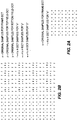
- FIG. 2A is graphical representation of the relative spacing of samples of an frame-mode encoded original pixel block and superimposed samples of a pixel block resulting from a 4:1 resizing of the original pixel block.
- FIG. 2A depicts a frame-encoded 8x8 block of original pixel samples, where each original block sample is denoted by an "x".
- superimposed over the 8x8 pixel block is a 4x4 pixel block comprising a 4:1 resized (i.e., compressed) version of the original 8x8 pixel block, where each resized block sample is denoted by an "*".
- the resized pixel block is formed by processing the original 8x8 pixel block according to an 8x8 discrete cosine transform (DCT) to produce an 8x8 DCT coefficient block.
- DCT discrete cosine transform
- This DCT domain resizing technique works well for a video frame comprising only frame mode encoded macroblocks, such as presented in FIG. 2A.
- the IDCT used to produce the resized pixel block from the truncated DCT coefficient block may be performed as a two dimensional IDCT (i.e., a 2D NxN IDCT) or as two one-dimensional IDCTs (i.e., a 1-D N-point IDCT is computed for each of the N lines, and then a 1-D N-point IDCT is computed for each column of the result).
- a two dimensional IDCT i.e., a 2D NxN IDCT
- two one-dimensional IDCTs i.e., a 1-D N-point IDCT is computed for each of the N lines, and then a 1-D N-point IDCT is computed for each column of the result.
- FIG. 2B is graphical representation of the relative spacing of samples of a mixed frame-mode encoded and field-mode encoded original pixel block and superimposed samples of a pixel block resulting from a 4:1 resizing of the original pixel block. Specifically, FIG. 2B depicts a 16x16 block of original pixel samples in which the "left" half of the samples (i.e., the leftmost two 8x8 macroblocks) have been frame-mode encoded while the "right" half of the samples (i.e., the rightmost two 8x8 macroblocks) have been field-mode encoded.
- the original frame-mode encoded samples are each denoted by an "x"; the original field-mode encoded sample associated with a top field are each denoted by a "z"; the original field-mode encoded sample associated with a bottom field are each denoted by a "z”.
- an 8x8 resized pixel block is produces that includes correctly spaced pixel samples and incorrectly spaced pixel samples.
- the resized samples associated with the frame-mode encoded pixel blocks (which are each denoted by a "*") are appropriately spaced with respect to the original samples (which are each denoted by a "x").
- the resized samples associated with the field-mode encoded pixel blocks are not appropriately spaced with respect to the original samples (which are each denoted by a "z” for the top field and a “y” for the bottom field).
- the left and right resized blocks are not properly aligned (i.e., the "*" samples are not in the same row as the and "•” samples).
- FIG. 1 depicts an embodiment of an MPEG-like decoder 100 according to an embodiment of the present invention.
- the decoder 100 of FIG. 1 receives and decodes a compressed video information stream IN to produce a video output stream OUT.
- the video output stream OUT is suitable for coupling to, e.g., a display driver circuit within a presentation device (not shown).
- the MPEG-like decoder 100 comprises an input buffer memory module 111, a variable length decoder (VLD) module 112, an inverse quantizer (IQ) module 113, an inverse discrete cosine transform (IDCT) module 114, a summer 115, a motion compensation module 116, an output buffer module 118, an anchor frame memory module 117 and a motion vector (MV) resizer 130.
- VLD variable length decoder
- IQ inverse quantizer
- IDCT inverse discrete cosine transform
- MV motion vector
- the input buffer memory module 111 receives the compressed video stream IN, illustratively a variable length encoded bitstream representing, e.g., a high definition television signal (HDTV) or standard definition television signal (SDTV) output from a transport demultiplexer/decoder circuit (not shown).
- the input buffer memory module 111 is used to temporarily store the received compressed video stream IN until the variable length decoder module 112 is ready to accept the video data for processing.
- the VLD 112 has an input coupled to a data output of the input buffer memory module 111 to retrieve, e.g., the stored variable length encoded video data as data stream S1.
- the VLD 112 decodes the retrieved data to produce a constant length bit stream S2 comprising quantized prediction error DCT coefficients that is coupled to the IQ module 113.
- the VLD 112 also produces a motion vector stream MV that is coupled to the motion vector resizer 130, and a block information stream DATA that is coupled to the motion vector resizer 130 and the IDCT module 114.
- the IQ module 113 performs an inverse quantization operation upon constant length bit stream S2 to produce a bit stream S3 comprising quantized prediction error DCT coefficients in a standard form.
- the IDCT module 114 performs an inverse discrete cosine transform operation upon bit stream S3 to produce a reduced image size bitstream S4 comprising pixel-by-pixel prediction errors.
- the IDCT operates, on a block by block basis, to reduce the size of the image represented by the information in bit stream S3. This size reduction is implemented by discarding (i.e., truncating) a portion of the DCT coefficients associated with each block prior to performing the IDCT operation.
- the operation of the IDCT module 114 will be described in more detail below with respect to FIG. 3 and FIG. 5. Briefly, in one embodiment described below with respect to FIG. 3, the IDCT processes, e.g., an 8x8 DCT coefficient block using a matrix that is slightly different than the standard matrix.
- the matrix used has been selected to impart a half pel vertical shift to those resized samples associated with field-mode encoding.
- the IDCT processes e.g., an 8x8 DCT coefficient block using one or more of a plurality of matrices that are slightly different than the standard matrix.
- the utilized matrix or matrices are used have been selected to impart a predetermined vertical shift to those resized samples associated with field-mode encoding depending upon whether, e.g., a top field or a bottom field is being processed.
- the summer 115 adds the reduced image size pixel-by-pixel prediction error stream S4 to a motion compensated predicted pixel value stream S6 produced by the motion compensation module 116.
- the output of summer 115 is, in the exemplary embodiment, a reduced size video stream S5 comprising reconstructed pixel values.
- the reduced size video stream S5 produced by summer 115 is coupled to the anchor frame memory 117 and the output buffer module 118.
- the anchor frame memory module 117 receives and stores the compressed video stream S5.
- the size of the anchor frame memory module 117 may be reduced by an amount consistent with the compression ratio utilized.
- the motion vector resizer 130 receives the motion vector stream MV and block information stream DATA from the VLD 112.
- the motion vector stream MV comprises motion vector information to be used by the motion compensation module 116 to predict individual macroblocks based upon image information stored in the anchor frame memory module. However, since the image information stored in the anchor frame memory module 117 has been scaled by the IDCT module 116, it is also necessary to scale motion vector data used to predict macroblocks using the scaled pixel information.
- the scaled motion vectors MV are coupled to the motion compensation module 116 via path MV'.
- the motion compensation module 116 accesses the compressed (i.e., scaled) image information stored in memory module 117 via signal path S7 and the scaled motion vector(s) MV' to produce a scaled predicted macroblock. That is, the motion compensation module 116 utilizes one or more stored anchor frames (e.g., the reduced resolution pixel blocks generated with respect to the most recent I-frame or P-frame of the video signal produced at the output of the summer 115), and the motion vector(s) MV' received from the motion vector resizer 130, to calculate the values for each of a plurality of scaled predicted macroblocks forming a scaled predicted information stream.
- anchor frames e.g., the reduced resolution pixel blocks generated with respect to the most recent I-frame or P-frame of the video signal produced at the output of the summer 115
- FIG. 3 depicts a flow diagram of a method for performing an inverse discrete cosine transform routine suitable for use in the MPEG-like decoder of FIG. 1.
- the method 300 of FIG. 3 is suitable for use in, e.g., the IDCT module 116 of the MPEG-like decoder of FIG. 1.
- the IDCT routine 300 is entered at step 305 and proceeds to step 310, where DCT coefficients representative of a pixel block are received by, e.g., the IDCT module 116 of FIG. 1.
- the routine 300 then proceeds to step 312, where the DCT coefficients representative of the received pixel block are truncated in accordance with the resizing or scaling to be imparted to the image or picture including the represented pixel block.
- the received DCT coefficients comprise an 8x8 DCT coefficient block representative of an 8x8 pixel block
- the resized image or picture is to be 1 ⁇ 4 the resolution of the original picture or image (i.e., vertical and horizontal information reduced by 1 ⁇ 2 each)
- all the received DCT coefficients except the 4x4 DCT coefficient "sub-block" representing lower vertical and horizontal spatial frequency information are truncated.
- the routine 300 then proceeds to step 315.
- a query is made as to whether the received DCT coefficients were encoded according to a "mixed mode" DCT encoding regime. That is, a query is made to determine if the pixel block represented by the received DCT coefficients is part of an image or picture that was encoded using both field-mode and frame-mode DCT encoding. If the query at step 315 is answered negatively (i.e., frame-mode only or field mode only), then the routine 300 proceeds to step 320. If the query at step 315 is answered affirmatively (i.e., mixed frame-mode and field mode encoding), then the routine 300 proceeds to step 325.
- a "mixed mode" DCT encoding regime That is, a query is made to determine if the pixel block represented by the received DCT coefficients is part of an image or picture that was encoded using both field-mode and frame-mode DCT encoding. If the query at step 315 is answered negatively (i.e., frame-mode only or field mode only), then the routine 300 proceeds
- the routine 300 performs an IDCT of the truncated DCT coefficients using DCT basis functions (e.g., as defined by the coefficient matrix) that are standard for the size of the pixel block represented by the received DCT coefficients and the resizing imparted to the image or picture including the represented pixel block.
- Table 1 depicts an IDCT coefficient matrix suitable for use performing an IDCT operation on a 4x4 DCT coefficient block to produce a 4x4 pixel block.
- Table 1 0.5000 0.6533 0.5000 0.2706 0.5000 0.2706 -0.5000 -0.6533 0.5000 -0.2706 -0.5000 0.6533 0.5000 -0.6533 0.5000 0.2706
- step 320 for the case of a 4x4 DCT coefficient matrix
- the truncated DCT coefficient block (X) is pre-multiplied by matrix D and post-multiplied by the inverse of matrix D (i.e., D') to produce a 4x4 pixel block (x), which is then coupled to, e.g., adder 115 as reduced image size bitstream S4.
- the routine 300 then proceeds to step 310, where the next DCT coefficient block is received.
- a query is made as to whether the particular "mixed-mode" DCT coefficient block received at step 310 comprises a frame-mode coded DCT coefficient block. If the query at step 315 is answered negatively, then the routine 300 proceeds to step 330. If the query at step 315 is answered affirmatively, then the routine 300 proceeds to step 335.
- a query is made as to whether the particular field-mode DCT coefficient block received at step 310 is part of a bottom field. If the query at step 330 is answered affirmatively (i.e., the DCT coefficient block includes bottom field information), then the routine 300 proceeds to step 335. If the query at step 315 is answered negatively (i.e., the DCT coefficient block includes top field information), then the routine 300 proceeds to step 320.
- the routine 300 performs an IDCT of the truncated DCT coefficients using basis functions (as defined by the coefficient matrix D) that are modified such that a vertical pixel-domain shift is imparted to the resulting pixel block produced by the IDCT module 116.
- basis functions as defined by the coefficient matrix D
- an alternate pre-multiplication matrix (denoted as matrix "E” by the inventors) is used, as shown below with respect to equation 3.
- the alternate matrix E corresponds to a slightly skewed sub-sampling of the 8 point DCT basis functions. That is, the entries in Table 2 are samples of an 8-point IDCT matrix selected to impart, illustratively, a 1 ⁇ 2 pel shift vertically downward in the original pixel domain resolution.
- Table 2 0.5000 0.5878 0.2706 -0.1379 0.5000 0.1379 -0.6532 -0.3928 0.5000 -0.3928 -0.2706 0.6934 0.5000 -0.6934 0.6532 -0.5878
- step 335 (for the case of a 4x4 DCT coefficient matrix) the truncated DCT coefficient block (X) is pre-multiplied by matrix E and post-multiplied by the transpose of matrix D (i.e., D') to produce a 4x4 pixel block (2x), which is then coupled to, e.g., adder 115 as reduced image size bitstream S4.
- the routine 300 then proceeds to step 310, where the next DCT coefficient block is received.
- the alternate matrix E depicted above in Table 2 may be used to compensate for the pixel misalignment described above with respect to FIG. 2B by shifting down some pixel positions by half pel in vertical direction. More precisely, it can be used to compute the modified IDCT for the frame-DCT and for the bottom field DCT in field-DCT mode.
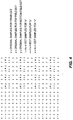
- FIG. 4 is graphical representation of the relative spacing of samples of a mixed frame-mode encoded and field-mode encoded original pixel block and superimposed samples of a pixel block resulting from a 4:1 resizing of the original pixel block according to the method of FIG. 3. Specifically, FIG. 4 depicts a 16x16 block of original pixel samples in which the "left" half of the samples (i.e., the leftmost two 8x8 macroblocks) have been frame-mode encoded while the "right" half of the samples (i.e., the rightmost two 8x8 macroblocks) have been field-mode encoded.
- the original frame-mode encoded samples are each denoted by an "x"; the original field-mode encoded sample associated with a top field are each denoted by a "z"; the original field-mode encoded sample associated with a bottom field are each denoted by a "z”.
- an 8x8 resized pixel block is produces that includes correctly aligned pixel samples that are incorrectly spaced with respect to the original pixel samples.
- the resized samples associated with the frame-mode encoded pixel blocks (which are each denoted by a "*") and the resized samples associated with the bottom field-mode encoded pixel blocks (which are each denoted by a "•”) have been shifted vertically downward by a 1 ⁇ 2 pel, while the resized samples associated with the top field-mode encoded pixel blocks (which are each denoted by a ) are in the same position as previously depicted with respect to FIG. 2B.
- the method 300 of FIG. 3 addresses the pixel alignment problem such that an image or picture represented by the received "mixed mode" DCT coefficient blocks will avoid artifacts due to pixel alignment errors (i.e., phase errors).
- the method 300 of FIG. 3 provides an efficient solution to the phase error problem, it must be noted that the method 300 does shift the actual position of the reconstructed pixel blocks to the border of the blocks. Thus, in applications where proximity to the pixel border results in additional artifacts, the method 300 of FIG. 3 will need to be modified to avoid such "blocking" artifacts.
- FIG. 5 depicts a flow diagram of a method for performing an inverse discrete cosine transform routine suitable for use in the MPEG-like decoder of FIG. 1.
- the method 500 of FIG. 5 is suitable for use in, e.g., the IDCT module 116 of the MPEG-like decoder of FIG. 1.
- the method 500 of FIG. 5 compensates for the border block problem described above with respect to FIG. 3 by providing phase error correction of "mixed mode" DCT coefficient blocks without shifting the reconstructed pixels to the border of their respective blocks.
- the IDCT routine 500 is entered at step 505 and proceeds to step 508, where top field and bottom field alternate IDCT matrices (E) are calculated according to the amount of vertical shifting to be imparted to the top and bottom fields pixels.
- the top and bottom alternate coefficient matrices (E T and E B , respectively) are calculated such that IDCT performed on the DCT coefficient blocks representing the respective fields will yield pixel blocks that are properly aligned and without phase error.
- equation 4 provides a general solution to the alternate matrix calculation.
- the matrix E T is calculated using equation 4 to produce the matrix shown below in Table 3.
- the matrix E B is calculated using equation 4 to produce the matrix shown below in Table 4.
- Table 2 may be obtained by sub-sampling the original 8x8 basis functions (e.g., the matrix coefficients)
- the values within Tables 3 and 4 do not correspond to a sub-sampling of the original DCT coefficients. That is, the values within Tables 3 and 4 require a sampling of the continuous domain basis functions as expressed in equation 4 at the desired sampling points.
- Table 3 0.5000 0.6766 0.5878 0.4485 0.5000 0.3333 -0.3928 -0.7036 0.5000 -0.2052 -0.5878 0.5465 0.5000 -0.6235 0.3928 -0.0693
- Table 4 0.5000 0.6235 0.3928 0.0693 0.5000 0.2052 -0.5878 -0.5465 0.5000 -0.3333 -0.3928 0.7036 0.5000 0.6766 0.5878 -0.4485
- the routine 500 proceeds to step 510, where DCT coefficients representative of a pixel block are received by, e.g., the IDCT module 116 of FIG. 1.
- the routine 500 then proceeds to step 512, where the DCT coefficients representative of the received pixel block are resized (e.g., truncated) in accordance with the resizing or scaling to be imparted to the image or picture including the represented pixel block.
- the routine 500 then proceeds to step 525.
- a query is made as to whether the received DCT coefficient block comprises a frame-mode coded DCT coefficient block. If the query at step 525 is answered affirmatively, then the routine 500 proceeds to step 520. If the query at step 525 is answered negatively (i.e., field-mode DCT coding used), then the routine 500 proceeds to step 530.
- the routine 500 performs an IDCT of the resized (e.g., truncated) DCT coefficients using basis functions (as defined by the coefficient matrix) that are standard for the size of the pixel block represented by the received DCT coefficients and the resizing imparted to the image or picture including the represented pixel block.
- Table 1 depicts an IDCT coefficient matrix suitable for use performing an IDCT operation on a 4x4 DCT coefficient block to produce a 4x4 pixel block.
- the routine 500 then proceeds to step 510, where the next DCT coefficient block is received.
- a query is made as to whether the received field-mode coded DCT coefficient block comprises a bottom field block. If the query at step 530 is answered affirmatively, then the routine 500 proceeds to step 540. If the query at step 530 is answered negatively, then the routine 500 proceeds to step 545.
- the routine 500 performs an IDCT of the resized bottom field DCT coefficients using the basis function defined by the coefficient matrix EB previously calculated at step 508.
- Table 4 depicts an IDCT coefficient matrix suitable for use performing an IDCT operation on a 4x4 field-mode coded (bottom field) DCT coefficient block to produce a 4x4 pixel block.
- the routine 500 then proceeds to step 510, where the next DCT coefficient block is received.
- the routine 500 performs an IDCT of the resized top field DCT coefficients using the basis function defined by the coefficient matrix ET previously calculated at step 508.
- Table 3 depicts an IDCT coefficient matrix suitable for use performing an IDCT operation on a 4x4 field-mode coded (top field) DCT coefficient block to produce a 4x4 pixel block.
- the routine 500 then proceeds to step 510, where the next DCT coefficient block is received.
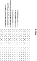
- FIG. 6 is graphical representation of the relative spacing of samples of a mixed frame-mode encoded and field-mode encoded original pixel block and superimposed samples of a pixel block resulting from a 4:1 resizing of the original pixel block according to the method of FIG. 5. Specifically, FIG. 6 depicts a 16x16 block of original pixel samples in which the "left" half of the samples (i.e., the leftmost two 8x8 macroblocks) have been frame-mode encoded while the "right" half of the samples (i.e., the rightmost two 8x8 macroblocks) have been field-mode encoded.
- the original frame-mode encoded samples are each denoted by an "x"; the original field-mode encoded sample associated with a top field are each denoted by a "z"; the original field-mode encoded sample associated with a bottom field are each denoted by a "z”.
- an 8x8 resized pixel block is produces that includes correctly aligned pixel samples that are correctly spaced with respect to the original pixel samples. Specifically, the resized samples associated with the frame-mode encoded pixel blocks (which are each denoted by a "*”) have not been shifted, the resized samples associated with the bottom field-mode encoded pixel blocks (which are each denoted by a "•”) have been shifted vertically downward by a 1 ⁇ 2 pel, and the resized samples associated with the top field-mode encoded pixel blocks (which are each denoted by a ) have been shifted upward by 1 ⁇ 4 pel.
- the method 500 of FIG. 5 addresses the pixel alignment problem such that an image or picture represented by the received "mixed mode" DCT coefficient blocks will avoid artifacts due to pixel alignment errors (i.e., phase errors) and without producing block border artifacts.
- the new resolution is one fourth of the original resolution
- the bottom field, field-mode sample is vertically shifted downward by a 3/2 pel (original resolution)
- the top field, field-mode sample is vertically shifted upward by a 3/2 pel (original resolution) to properly align the frame-mode and field-mode samples.
- the embodiments of the present invention have been described primarily in terms of scaling down (i.e., reducing pixel domain information prior to storage), the embodiments of the present invention are well suited to scaling up (i.e., increasing pixel domain information).
- scaling up of pixel domain information and motion vector information is especially applicable to applications requiring the presentation of low resolution image information using a high resolution display device.
- SDTV standard definition television
- HDTV high definition television
- the present invention can be embodied in the form of computer-implemented processes and apparatuses for practicing those processes.
- the present invention also can be embodied in the form of computer program code embodied in tangible media, such as floppy diskettes, CD-ROMs, hard drives, or any other computer readable storage medium, wherein, when the computer program code is loaded into and executed by a computer, the computer becomes an apparatus for practicing the invention.
- the present invention can also be embodied in the form of computer program code, for example whether stored in a storage medium, loaded into and/or executed by a computer, or transmitted over some transmission medium, such as over electrical wiring or cabling, through fiber optics, or via electromagnetic radiation, wherein, when the computer program code is loaded into and executed by a computer, the computer becomes an apparatus for practicing the invention.
- computer program code segments configure the microprocessor to create specific logic circuits.
Landscapes
- Engineering & Computer Science (AREA)
- Multimedia (AREA)
- Signal Processing (AREA)
- Physics & Mathematics (AREA)
- General Physics & Mathematics (AREA)
- Theoretical Computer Science (AREA)
- Compression Or Coding Systems Of Tv Signals (AREA)
- Compression Of Band Width Or Redundancy In Fax (AREA)
Abstract
Description
- The present invention relates to a method and apparatus for resizing an image frame including field-mode encoding. An illustrative embodiment of the present invention relates to communications systems generally and, more particularly, the invention relates to a method and apparatus for resizing an image frame including field-mode encoding in an information stream decoder, such as an MPEG-like video decoder.
- In several communications systems the data to be transmitted is compressed so that the available bandwidth is used more efficiently. For example, the Moving Pictures Experts Group (MPEG) has promulgated several standards relating to digital data delivery systems. The first, known as MPEG-1 refers to ISO/IEC standards 11172 and is incorporated herein by reference. The second, known as MPEG-2, refers to ISO/IEC standards 13818 and is incorporated herein by reference. A compressed digital video system is described in the Advanced Television Systems Committee (ATSC) digital television standard document A/53, and is incorporated herein by reference.
- The above-referenced standards describe data processing and manipulation techniques that are well suited to the compression and delivery of video, audio and other information using fixed or variable length digital communications systems. In particular, the above-referenced standards, and other "MPEG-like" standards and techniques, compress, illustratively, video information using intra-frame coding techniques (such as run-length coding, Huffman coding and the like) and inter-frame coding techniques (such as forward and backward predictive coding, motion compensation and the like). Specifically, in the case of video processing systems, MPEG and MPEG-like video processing systems are characterized by prediction-based compression encoding of video frames with or without intra- and/or inter-frame motion compensation encoding.
- It is known to compress (i.e., resize) image information to reduce decoder anchor frame memory requirements or to reduce decoder processing resources in systems utilizing relatively low resolution display devices. For example, in the case of an 8x8 block of DCT coefficients received by an MPEG-like decoder, it is known to consider only the 4x4 lower block of DCT coefficients (i.e., truncate the three 4x4 higher order blocks), and to compute a 4x4 pixel block for storage as anchor frame information. Unfortunately, present techniques for resizing images including field-mode coded DCT coefficients do not produce adequate results, especially if the images include both frame-mode and field-mode DCT coefficients. Therefore, it is seen to be desirable to provide a method and apparatus that addresses these and other problems in the art.
- The present invention seeks to provide a method and apparatus for reducing information artifacts, such as phase error artifacts, imparted to a field-mode encoded video information stream during inverse discrete cosine transform (IDCT) processing within, e.g., an MPEG-like decoder producing a resized image frame(s) from an original image frame(s). That is, the present invention seeks to adapt at least a portion of the DCT coefficients used during the IDCT processing such that pixel domain correction is imparted to the resized image frame(s) during the IDCT processing of the DCT-domain information forming the original image frame(s).
- Aspects of the present invention are set out in the claims to which attention is invited. For a better understanding of the present invention refeence will now be made by way of example to the accompanying drawings, in which:
- FIG. 1 depicts an embodiment of an MPEG-like decoder including apparatus according to an embodiment of the present invention;
- FIG. 2A is graphical representation of the relative spacing of samples of an frame-mode encoded original pixel block and superimposed samples of a pixel block resulting from a 4:1 resizing of the original pixel block;
- FIG. 2B is graphical representation of the relative spacing of samples of a mixed frame-mode encoded and field-mode encoded original pixel block and superimposed samples of a pixel block resulting from a 4:1 resizing of the original pixel block;
- FIG. 3 depicts a flow diagram of a method for performing an inverse discrete cosine transform routine suitable for use in the MPEG-like decoder of FIG. 1;
- FIG. 4 is graphical representation of the relative spacing of samples of a mixed frame-mode encoded and field-mode encoded original pixel block and superimposed samples of a pixel block resulting from a 4:1 resizing of the original pixel block according to the method of FIG. 3;
- FIG. 5 depicts a flow diagram of a method for performing an inverse discrete cosine transform routine suitable for use in the MPEG-like decoder of FIG. 1;
- FIG. 6 is graphical representation of the relative spacing of samples of a mixed frame-mode encoded and field-mode encoded original pixel block and superimposed samples of a pixel block resulting from a 4:1 resizing of the original pixel block according to the method of FIG. 5.
- To facilitate understanding, identical reference numerals have been used, where possible, to designate identical elements that are common to the figures.
- Embodiments of the present invention will be described within the context of a video decoder, illustratively an MPEG-2 video decoding system that receives and decodes a compressed video information stream IN to produce a video output stream OUT. However, it will be apparent to those skilled in the art that embodiments of the invention are applicable to any video processing system, including those systems adapted to DVB, MPEG-1, MPEG-2 and other information streams. Specifically, embodiments of the present invention are particularly well suited to any systems utilizing both frame-mode predicted macroblocks and filed-mode predicted macroblocks, such as MPEG-2 video decoding systems.
- FIG. 2A is graphical representation of the relative spacing of samples of an frame-mode encoded original pixel block and superimposed samples of a pixel block resulting from a 4:1 resizing of the original pixel block. Specifically, FIG. 2A depicts a frame-encoded 8x8 block of original pixel samples, where each original block sample is denoted by an "x". Superimposed over the 8x8 pixel block is a 4x4 pixel block comprising a 4:1 resized (i.e., compressed) version of the original 8x8 pixel block, where each resized block sample is denoted by an "*".
- The resized pixel block is formed by processing the original 8x8 pixel block according to an 8x8 discrete cosine transform (DCT) to produce an 8x8 DCT coefficient block. After truncating (or ignoring) all DCT coefficients except the 4x4 DCT coefficient block representing the lower spatial frequencies of the original 8x8 pixel block, an inverse DCT is performed on the remaining 4x4 DCT coefficient block to produce the 4x4 resized pixel block. This DCT domain resizing technique works well for a video frame comprising only frame mode encoded macroblocks, such as presented in FIG. 2A. It must be noted that the IDCT used to produce the resized pixel block from the truncated DCT coefficient block may be performed as a two dimensional IDCT (i.e., a 2D NxN IDCT) or as two one-dimensional IDCTs (i.e., a 1-D N-point IDCT is computed for each of the N lines, and then a 1-D N-point IDCT is computed for each column of the result).
- FIG. 2B is graphical representation of the relative spacing of samples of a mixed frame-mode encoded and field-mode encoded original pixel block and superimposed samples of a pixel block resulting from a 4:1 resizing of the original pixel block. Specifically, FIG. 2B depicts a 16x16 block of original pixel samples in which the "left" half of the samples (i.e., the leftmost two 8x8 macroblocks) have been frame-mode encoded while the "right" half of the samples (i.e., the rightmost two 8x8 macroblocks) have been field-mode encoded. The original frame-mode encoded samples are each denoted by an "x"; the original field-mode encoded sample associated with a top field are each denoted by a "z"; the original field-mode encoded sample associated with a bottom field are each denoted by a "z".
- After processing the 16x16 block using the DCT domain resizing method described above with respect to FIG. 2A, an 8x8 resized pixel block is produces that includes correctly spaced pixel samples and incorrectly spaced pixel samples. Specifically, the resized samples associated with the frame-mode encoded pixel blocks (which are each denoted by a "*") are appropriately spaced with respect to the original samples (which are each denoted by a "x"). However, the resized samples associated with the field-mode encoded pixel blocks (which are each denoted by afor the top field and a "•" for the bottom field) are not appropriately spaced with respect to the original samples (which are each denoted by a "z" for the top field and a "y" for the bottom field). Moreover, the left and right resized blocks are not properly aligned (i.e., the "*" samples are not in the same row as the
 and "•" samples). These errors are present because the original field-mode encoded pixels within a particular field are vertically separated by two lines, unlike the original frame-mode encoded pixels which are vertically separated by only one line. Thus, there is a half picture element (pel) error introduced during the DCT domain resizing process.
 - It is important to note that in the case of a picture including only field-mode encoded macroblocks, the half pel error is less noticeable, since the half pel error is constant across the picture. However, where mixed frame-mode and filed-mode encoded macroblocks exist in a single picture (as depicted in FIG. 2B), the half pel error is extremely noticeable. Furthermore, if the picture includes both field and frame macroblocks, the described distortion cannot be corrected by post-filtering the complete frame.
- FIG. 1 depicts an embodiment of an MPEG-like decoder 100 according to an embodiment of the present invention. Specifically, the decoder 100 of FIG. 1 receives and decodes a compressed video information stream IN to produce a video output stream OUT. The video output stream OUT is suitable for coupling to, e.g., a display driver circuit within a presentation device (not shown).
- The MPEG-like decoder 100 comprises an input
buffer memory module 111, a variable length decoder (VLD)module 112, an inverse quantizer (IQ)module 113, an inverse discrete cosine transform (IDCT) module 114, asummer 115, amotion compensation module 116, anoutput buffer module 118, an anchorframe memory module 117 and a motion vector (MV)resizer 130. - The input
buffer memory module 111 receives the compressed video stream IN, illustratively a variable length encoded bitstream representing, e.g., a high definition television signal (HDTV) or standard definition television signal (SDTV) output from a transport demultiplexer/decoder circuit (not shown). The inputbuffer memory module 111 is used to temporarily store the received compressed video stream IN until the variablelength decoder module 112 is ready to accept the video data for processing. TheVLD 112 has an input coupled to a data output of the inputbuffer memory module 111 to retrieve, e.g., the stored variable length encoded video data as data stream S1. - The
VLD 112 decodes the retrieved data to produce a constant length bit stream S2 comprising quantized prediction error DCT coefficients that is coupled to theIQ module 113. TheVLD 112 also produces a motion vector stream MV that is coupled to themotion vector resizer 130, and a block information stream DATA that is coupled to themotion vector resizer 130 and the IDCT module 114. - The
IQ module 113 performs an inverse quantization operation upon constant length bit stream S2 to produce a bit stream S3 comprising quantized prediction error DCT coefficients in a standard form. - The IDCT module 114 performs an inverse discrete cosine transform operation upon bit stream S3 to produce a reduced image size bitstream S4 comprising pixel-by-pixel prediction errors. Importantly, the IDCT operates, on a block by block basis, to reduce the size of the image represented by the information in bit stream S3. This size reduction is implemented by discarding (i.e., truncating) a portion of the DCT coefficients associated with each block prior to performing the IDCT operation. The operation of the IDCT module 114 will be described in more detail below with respect to FIG. 3 and FIG. 5. Briefly, in one embodiment described below with respect to FIG. 3, the IDCT processes, e.g., an 8x8 DCT coefficient block using a matrix that is slightly different than the standard matrix. The matrix used has been selected to impart a half pel vertical shift to those resized samples associated with field-mode encoding. In another embodiment of the invention described below with respect to FIG. 5, the IDCT processes, e.g., an 8x8 DCT coefficient block using one or more of a plurality of matrices that are slightly different than the standard matrix. The utilized matrix or matrices are used have been selected to impart a predetermined vertical shift to those resized samples associated with field-mode encoding depending upon whether, e.g., a top field or a bottom field is being processed.
- The
summer 115 adds the reduced image size pixel-by-pixel prediction error stream S4 to a motion compensated predicted pixel value stream S6 produced by themotion compensation module 116. Thus, the output ofsummer 115 is, in the exemplary embodiment, a reduced size video stream S5 comprising reconstructed pixel values. The reduced size video stream S5 produced bysummer 115 is coupled to theanchor frame memory 117 and theoutput buffer module 118. - The anchor
frame memory module 117 receives and stores the compressed video stream S5. Advantageously, the size of the anchorframe memory module 117 may be reduced by an amount consistent with the compression ratio utilized. - The
motion vector resizer 130 receives the motion vector stream MV and block information stream DATA from theVLD 112. The motion vector stream MV comprises motion vector information to be used by themotion compensation module 116 to predict individual macroblocks based upon image information stored in the anchor frame memory module. However, since the image information stored in the anchorframe memory module 117 has been scaled by theIDCT module 116, it is also necessary to scale motion vector data used to predict macroblocks using the scaled pixel information. The scaled motion vectors MV are coupled to themotion compensation module 116 via path MV'. - The
motion compensation module 116 accesses the compressed (i.e., scaled) image information stored inmemory module 117 via signal path S7 and the scaled motion vector(s) MV' to produce a scaled predicted macroblock. That is, themotion compensation module 116 utilizes one or more stored anchor frames (e.g., the reduced resolution pixel blocks generated with respect to the most recent I-frame or P-frame of the video signal produced at the output of the summer 115), and the motion vector(s) MV' received from themotion vector resizer 130, to calculate the values for each of a plurality of scaled predicted macroblocks forming a scaled predicted information stream. - FIG. 3 depicts a flow diagram of a method for performing an inverse discrete cosine transform routine suitable for use in the MPEG-like decoder of FIG. 1. The
method 300 of FIG. 3 is suitable for use in, e.g., theIDCT module 116 of the MPEG-like decoder of FIG. 1. - The IDCT routine 300 is entered at
step 305 and proceeds to step 310, where DCT coefficients representative of a pixel block are received by, e.g., theIDCT module 116 of FIG. 1. The routine 300 then proceeds to step 312, where the DCT coefficients representative of the received pixel block are truncated in accordance with the resizing or scaling to be imparted to the image or picture including the represented pixel block. For example, if the received DCT coefficients comprise an 8x8 DCT coefficient block representative of an 8x8 pixel block, and the resized image or picture is to be ¼ the resolution of the original picture or image (i.e., vertical and horizontal information reduced by ½ each), then all the received DCT coefficients except the 4x4 DCT coefficient "sub-block" representing lower vertical and horizontal spatial frequency information are truncated. The routine 300 then proceeds to step 315. - At step 315 a query is made as to whether the received DCT coefficients were encoded according to a "mixed mode" DCT encoding regime. That is, a query is made to determine if the pixel block represented by the received DCT coefficients is part of an image or picture that was encoded using both field-mode and frame-mode DCT encoding. If the query at
step 315 is answered negatively (i.e., frame-mode only or field mode only), then the routine 300 proceeds to step 320. If the query atstep 315 is answered affirmatively (i.e., mixed frame-mode and field mode encoding), then the routine 300 proceeds to step 325. - At
step 320, the routine 300 performs an IDCT of the truncated DCT coefficients using DCT basis functions (e.g., as defined by the coefficient matrix) that are standard for the size of the pixel block represented by the received DCT coefficients and the resizing imparted to the image or picture including the represented pixel block. Table 1 depicts an IDCT coefficient matrix suitable for use performing an IDCT operation on a 4x4 DCT coefficient block to produce a 4x4 pixel block.Table 1 0.5000 0.6533 0.5000 0.2706 0.5000 0.2706 -0.5000 -0.6533 0.5000 -0.2706 -0.5000 0.6533 0.5000 -0.6533 0.5000 0.2706 - It must be noted that an IDCT transform may be expressed as a matrix multiplication. For example, if X is the DCT transform of a signal x, D is the DCT coefficients matrix used in that DCT transform, and D' is the inverse , then the following mathematical relationships are established:


- Thus, at step 320 (for the case of a 4x4 DCT coefficient matrix) the truncated DCT coefficient block (X) is pre-multiplied by matrix D and post-multiplied by the inverse of matrix D (i.e., D') to produce a 4x4 pixel block (x), which is then coupled to, e.g.,
adder 115 as reduced image size bitstream S4. The routine 300 then proceeds to step 310, where the next DCT coefficient block is received. - At step 325 a query is made as to whether the particular "mixed-mode" DCT coefficient block received at
step 310 comprises a frame-mode coded DCT coefficient block. If the query atstep 315 is answered negatively, then the routine 300 proceeds to step 330. If the query atstep 315 is answered affirmatively, then the routine 300 proceeds to step 335. - At step 330 a query is made as to whether the particular field-mode DCT coefficient block received at
step 310 is part of a bottom field. If the query atstep 330 is answered affirmatively (i.e., the DCT coefficient block includes bottom field information), then the routine 300 proceeds to step 335. If the query atstep 315 is answered negatively (i.e., the DCT coefficient block includes top field information), then the routine 300 proceeds to step 320. - At
step 335, the routine 300 performs an IDCT of the truncated DCT coefficients using basis functions (as defined by the coefficient matrix D) that are modified such that a vertical pixel-domain shift is imparted to the resulting pixel block produced by theIDCT module 116. Continuing with the above example of an 8x8 DCT coefficient block reduced to a 4x4 DCT coefficient block for resizing the image or picture represented by that block, to obtain a different sampling pattern in the vertical direction such that a corrective shift may be made to compensate for the field-mode DCT coding (e.g., the ½ pel error discussed above with respect to FIG. 2B), an alternate pre-multiplication matrix (denoted as matrix "E" by the inventors) is used, as shown below with respect to equation 3.
- Therefore, to obtain a pixel block x2 including the appropriate ½ pel (original resolution) vertical shift downward, the alternate matrix E corresponds to a slightly skewed sub-sampling of the 8 point DCT basis functions. That is, the entries in Table 2 are samples of an 8-point IDCT matrix selected to impart, illustratively, a ½ pel shift vertically downward in the original pixel domain resolution.
Table 2 0.5000 0.5878 0.2706 -0.1379 0.5000 0.1379 -0.6532 -0.3928 0.5000 -0.3928 -0.2706 0.6934 0.5000 -0.6934 0.6532 -0.5878 - Thus, at step 335 (for the case of a 4x4 DCT coefficient matrix) the truncated DCT coefficient block (X) is pre-multiplied by matrix E and post-multiplied by the transpose of matrix D (i.e., D') to produce a 4x4 pixel block (2x), which is then coupled to, e.g.,
adder 115 as reduced image size bitstream S4. The routine 300 then proceeds to step 310, where the next DCT coefficient block is received. - The alternate matrix E depicted above in Table 2 may be used to compensate for the pixel misalignment described above with respect to FIG. 2B by shifting down some pixel positions by half pel in vertical direction. More precisely, it can be used to compute the modified IDCT for the frame-DCT and for the bottom field DCT in field-DCT mode.
- FIG. 4 is graphical representation of the relative spacing of samples of a mixed frame-mode encoded and field-mode encoded original pixel block and superimposed samples of a pixel block resulting from a 4:1 resizing of the original pixel block according to the method of FIG. 3. Specifically, FIG. 4 depicts a 16x16 block of original pixel samples in which the "left" half of the samples (i.e., the leftmost two 8x8 macroblocks) have been frame-mode encoded while the "right" half of the samples (i.e., the rightmost two 8x8 macroblocks) have been field-mode encoded. The original frame-mode encoded samples are each denoted by an "x"; the original field-mode encoded sample associated with a top field are each denoted by a "z"; the original field-mode encoded sample associated with a bottom field are each denoted by a "z".
- After processing the 16x16 block using the DCT domain resizing method described above with respect to FIG. 3, an 8x8 resized pixel block is produces that includes correctly aligned pixel samples that are incorrectly spaced with respect to the original pixel samples. Specifically, the resized samples associated with the frame-mode encoded pixel blocks (which are each denoted by a "*") and the resized samples associated with the bottom field-mode encoded pixel blocks (which are each denoted by a "•") have been shifted vertically downward by a ½ pel, while the resized samples associated with the top field-mode encoded pixel blocks (which are each denoted by a) are in the same position as previously depicted with respect to FIG. 2B. Thus, the
method 300 of FIG. 3 addresses the pixel alignment problem such that an image or picture represented by the received "mixed mode" DCT coefficient blocks will avoid artifacts due to pixel alignment errors (i.e., phase errors). - However, while the
method 300 of FIG. 3 provides an efficient solution to the phase error problem, it must be noted that themethod 300 does shift the actual position of the reconstructed pixel blocks to the border of the blocks. Thus, in applications where proximity to the pixel border results in additional artifacts, themethod 300 of FIG. 3 will need to be modified to avoid such "blocking" artifacts. - FIG. 5 depicts a flow diagram of a method for performing an inverse discrete cosine transform routine suitable for use in the MPEG-like decoder of FIG. 1. The
method 500 of FIG. 5 is suitable for use in, e.g., theIDCT module 116 of the MPEG-like decoder of FIG. 1. Specifically, themethod 500 of FIG. 5 compensates for the border block problem described above with respect to FIG. 3 by providing phase error correction of "mixed mode" DCT coefficient blocks without shifting the reconstructed pixels to the border of their respective blocks. - The IDCT routine 500 is entered at
step 505 and proceeds to step 508, where top field and bottom field alternate IDCT matrices (E) are calculated according to the amount of vertical shifting to be imparted to the top and bottom fields pixels. The top and bottom alternate coefficient matrices (ET and EB, respectively) are calculated such that IDCT performed on the DCT coefficient blocks representing the respective fields will yield pixel blocks that are properly aligned and without phase error. - Consider the case discussed above with respect to FIG. 3 and shown in FIGS. 2B (i.e., the 8x8 to 4x4 block resizing case). If the bottom field pixel information represented by field-mode coded DCT coefficients is vertically shifted down by ½ pel original pixel domain resolution, and the top field pixel information represented by field-mode coded DCT coefficients is vertically shifted up by ½ pel original pixel domain resolution, then the resulting pixel blocks will be properly positioned with respect to the pixel information represented by frame-mode coded DCT coefficients. It must be noted that since the field-mode DCT coefficients have half the resolution, the amount of shifting must be scaled accordingly (i.e., a ½ pel original pixel domain shift corresponds to a ¼ pel shift of field-mode data).
- Since the corresponding alternate matrix samples for top and bottom field-mode information do not correspond to sub-samples of a higher order IDCT coefficient (as in the example of FIG. 3), the new alternate matrices ET and EB are calculated (at step 508) according to equation 4 (below), where:
- i and j are the column and row position of a matrix element;
- SHIFT is the desired shift in the original domain resolution (in pels);
- N is the original DCT size (e.g., 8 denotes an 8x8 DCT coefficient block);
- C(i) is a constant defined as:
- C(i) = 0.5 for i=0; and
- C(i) = 1/√2 otherwise
- Thus,
equation 4 provides a general solution to the alternate matrix calculation. For example, for the desired quarter pel shift upward in DCT resolution domain (to be used with top-field DCT), the matrix ET is calculated usingequation 4 to produce the matrix shown below in Table 3. Similarly, for the desired half pel shift downward in DCT resolution domain (to be used with bottom-field DCT), the matrix EB is calculated usingequation 4 to produce the matrix shown below in Table 4. Thus, by replacing the original IDCT matrix D for the above matrices in the pre-multiplication portion of the IDCT processing step, the desired shifting in pixel position is obtained. - It should be noted that while the values within Table 2 may be obtained by sub-sampling the original 8x8 basis functions (e.g., the matrix coefficients), the values within Tables 3 and 4 do not correspond to a sub-sampling of the original DCT coefficients. That is, the values within Tables 3 and 4 require a sampling of the continuous domain basis functions as expressed in
equation 4 at the desired sampling points.Table 3 0.5000 0.6766 0.5878 0.4485 0.5000 0.3333 -0.3928 -0.7036 0.5000 -0.2052 -0.5878 0.5465 0.5000 -0.6235 0.3928 -0.0693 Table 4 0.5000 0.6235 0.3928 0.0693 0.5000 0.2052 -0.5878 -0.5465 0.5000 -0.3333 -0.3928 0.7036 0.5000 0.6766 0.5878 -0.4485 - After calculating the top and bottom field matrices ET and EB at
step 508, the routine 500 proceeds to step 510, where DCT coefficients representative of a pixel block are received by, e.g., theIDCT module 116 of FIG. 1. The routine 500 then proceeds to step 512, where the DCT coefficients representative of the received pixel block are resized (e.g., truncated) in accordance with the resizing or scaling to be imparted to the image or picture including the represented pixel block. The routine 500 then proceeds to step 525. - At step 525 a query is made as to whether the received DCT coefficient block comprises a frame-mode coded DCT coefficient block. If the query at
step 525 is answered affirmatively, then the routine 500 proceeds to step 520. If the query atstep 525 is answered negatively (i.e., field-mode DCT coding used), then the routine 500 proceeds to step 530. - At
step 520, the routine 500 performs an IDCT of the resized (e.g., truncated) DCT coefficients using basis functions (as defined by the coefficient matrix) that are standard for the size of the pixel block represented by the received DCT coefficients and the resizing imparted to the image or picture including the represented pixel block. Table 1 depicts an IDCT coefficient matrix suitable for use performing an IDCT operation on a 4x4 DCT coefficient block to produce a 4x4 pixel block. The routine 500 then proceeds to step 510, where the next DCT coefficient block is received. - At step 530 a query is made as to whether the received field-mode coded DCT coefficient block comprises a bottom field block. If the query at
step 530 is answered affirmatively, then the routine 500 proceeds to step 540. If the query atstep 530 is answered negatively, then the routine 500 proceeds to step 545. - At
step 540, the routine 500 performs an IDCT of the resized bottom field DCT coefficients using the basis function defined by the coefficient matrix EB previously calculated atstep 508. Table 4 depicts an IDCT coefficient matrix suitable for use performing an IDCT operation on a 4x4 field-mode coded (bottom field) DCT coefficient block to produce a 4x4 pixel block. The routine 500 then proceeds to step 510, where the next DCT coefficient block is received. - At
step 545, the routine 500 performs an IDCT of the resized top field DCT coefficients using the basis function defined by the coefficient matrix ET previously calculated atstep 508. Table 3 depicts an IDCT coefficient matrix suitable for use performing an IDCT operation on a 4x4 field-mode coded (top field) DCT coefficient block to produce a 4x4 pixel block. The routine 500 then proceeds to step 510, where the next DCT coefficient block is received. - FIG. 6 is graphical representation of the relative spacing of samples of a mixed frame-mode encoded and field-mode encoded original pixel block and superimposed samples of a pixel block resulting from a 4:1 resizing of the original pixel block according to the method of FIG. 5. Specifically, FIG. 6 depicts a 16x16 block of original pixel samples in which the "left" half of the samples (i.e., the leftmost two 8x8 macroblocks) have been frame-mode encoded while the "right" half of the samples (i.e., the rightmost two 8x8 macroblocks) have been field-mode encoded. The original frame-mode encoded samples are each denoted by an "x"; the original field-mode encoded sample associated with a top field are each denoted by a "z"; the original field-mode encoded sample associated with a bottom field are each denoted by a "z".
- After processing the 16x16 block using the DCT domain resizing method described above with respect to FIG. 5, an 8x8 resized pixel block is produces that includes correctly aligned pixel samples that are correctly spaced with respect to the original pixel samples. Specifically, the resized samples associated with the frame-mode encoded pixel blocks (which are each denoted by a "*") have not been shifted, the resized samples associated with the bottom field-mode encoded pixel blocks (which are each denoted by a "•") have been shifted vertically downward by a ½ pel, and the resized samples associated with the top field-mode encoded pixel blocks (which are each denoted by a) have been shifted upward by ¼ pel. Thus, the
method 500 of FIG. 5 addresses the pixel alignment problem such that an image or picture represented by the received "mixed mode" DCT coefficient blocks will avoid artifacts due to pixel alignment errors (i.e., phase errors) and without producing block border artifacts. - While the embodiments of the present invention have been described primarily in terms of scaling motion vectors and pixel domain information by a factor of two, it must be noted that the embodiments of the present invention are well suited to other scaling factors (integer and non-integer). For example, In FIG. 6, where the new resolution is one half of the original resolution, the bottom field, field-mode sample is vertically shifted downward by a half pel (original resolution), and the top field, field-mode sample is vertically shifted upward by a half pel (original resolution) to properly align the frame-mode and field-mode samples. Similarly, if the new resolution is one fourth of the original resolution, the bottom field, field-mode sample is vertically shifted downward by a 3/2 pel (original resolution), and the top field, field-mode sample is vertically shifted upward by a 3/2 pel (original resolution) to properly align the frame-mode and field-mode samples.
- Moreover, while the embodiments of the present invention have been described primarily in terms of scaling down (i.e., reducing pixel domain information prior to storage), the embodiments of the present invention are well suited to scaling up (i.e., increasing pixel domain information). Such scaling up of pixel domain information and motion vector information is especially applicable to applications requiring the presentation of low resolution image information using a high resolution display device. For example, the presentation of standard definition television (SDTV) on a high definition television (HDTV) display device. One skilled in the art and informed by the teachings of the present invention will readily devise additional and various modifications to the above-described embodiments of the invention.
- The present invention can be embodied in the form of computer-implemented processes and apparatuses for practicing those processes. The present invention also can be embodied in the form of computer program code embodied in tangible media, such as floppy diskettes, CD-ROMs, hard drives, or any other computer readable storage medium, wherein, when the computer program code is loaded into and executed by a computer, the computer becomes an apparatus for practicing the invention. The present invention can also be embodied in the form of computer program code, for example whether stored in a storage medium, loaded into and/or executed by a computer, or transmitted over some transmission medium, such as over electrical wiring or cabling, through fiber optics, or via electromagnetic radiation, wherein, when the computer program code is loaded into and executed by a computer, the computer becomes an apparatus for practicing the invention. When implemented on a general-purpose microprocessor, the computer program code segments configure the microprocessor to create specific logic circuits.
- Although various embodiments which incorporate the teachings of the present invention have been shown and described in detail herein, those skilled in the art can readily devise many other varied embodiments that still incorporate these teachings.
Claims (11)
- In a system for decoding a compressed image stream including discrete cosine transform (DCT) coefficient blocks representative of pixel blocks having a first resolution, a method comprising the steps of:resizing (312) a DCT coefficient block, said resized DCT coefficient block being representative of a pixel block having a second resolution;transforming (335), according to an inverse discrete cosine transform (IDCT), said resized DCT coefficient block to produce said pixel block having said second resolution, said step of transforming utilizing DCT basis functions adapted in response to an encoding mode of said DCT coefficient block.
- The method of claim 1, wherein said DCT basis functions are further adapted in response to a relationship between said first resolution and second resolution.
- The method of claim 1, wherein said step of transforming causes pixel domain information derived from field-mode DCT information to be appropriately aligned with pixel information derived from frame-mode DCT information.
- The method of claim 1, wherein said step of transforming comprises the steps of:determining (315) if a frame of DCT coefficient blocks including said DCT coefficient block has been encoded according to a single encoding mode; andin the case of said frame of DCT coefficient blocks being encoded according to a single encoding mode:
utilizing (320) a default set of DCT basis functions;in the case of said frame of DCT coefficient blocks not being encoded according to a single encoding mode:
utilizing said default set of DCT basis functions if said DCT encoding mode comprises a field-mode encoding mode and said DCT coefficient block represents a bottom field pixel block;
utilizing (335) a modified set of DCT basis functions if said DCT encoding mode comprises a frame-mode encoding mode; and
utilizing said modified set of DCT basis functions if said DCT encoding mode comprises a field-mode encoding mode and said DCT coefficient block represents a top field pixel block. - The method of claim 4, wherein:said default set of DCT basis functions is represented by a first matrix;said set of DCT basis functions derived by sub-sampling said default set of DCT basis functions is represented by a second matrix; andsaid second matrix is selected to impart a vertical shifting of said pixel block having said second resolution.
- The method of claim 5, wherein:said second resolution is one fourth of said first resolution; andsaid second matrix is selected to impart a 3/2 picture element (pel), with respect to said first resolution, vertical shifting of said pixel block having said second resolution.
- The method of claim 5, wherein:said second resolution is one half of said first resolution; andsaid second matrix is selected to impart a half pel, with respect to said first resolution, vertical shifting of said pixel block having said second resolution.
- The method of claim 1, wherein said step of transforming comprises the steps of:determining (525) if said DCT coefficient block has been encoded according to a frame-mode encoding mode or a field-mode encoding mode; andin the case of said DCT coefficient block having been encoded according to said frame-mode encoding mode:
performing (520) said IDCT using a default set of DCT basis functions;in the case of said DCT coefficient block having been encoded according to said field-mode encoding mode:
performing (545), in the case of said DCT coefficient block representing a top field pixel block, said IDCT using a first modified set of DCT basis functions; and
performing (540), in the case of said DCT coefficient block representing a bottom field pixel block, said IDCT using a second modified set of DCT basis functions. - The method of claim 8, wherein:said first modified set of DCT basis functions comprises said default set of DCT basis functions multiplied by a first set of DCT basis functions derived by sub-sampling said default set of DCT basis functions;said second modified set of DCT basis functions comprises said default set of DCT basis functions multiplied by a second set of DCT basis functions derived by sub-sampling said default set of DCT basis functions.
- In a system for decoding a compressed image stream (S1) including discrete cosine transform (DCT) coefficient blocks representative of pixel blocks having a first resolution, apparatus comprising:an inverse discrete cosine transform (IDCT) processor (114);
said IDCT processor resizing (300; 500) a DCT coefficient block to produce a resized DCT coefficient block representative of a pixel block having a second resolution; andsaid IDCT processor transforming, according to an inverse discrete cosine transform (IDCT) utilizing DCT basis functions adapted in response to an encoding mode of said DCT coefficient block, said resized DCT coefficient block to produce said pixel block having said second resolution. - The apparatus of claim 10, wherein:said IDCT processor determines if a frame of DCT coefficient blocks including said DCT coefficient block has been encoded according to a single encoding mode; andin the case of said frame of DCT coefficient blocks being encoded according to a single encoding mode:
said IDCT processor utilizes a default set of DCT basis functions;
in the case of said frame of DCT coefficient blocks not being encoded according to a single encoding mode:
said IDCT processor utilizes said default set of DCT basis functions if said DCT encoding mode comprises a field-mode encoding mode and said DCT coefficient block represents a bottom field pixel block;
said IDCT processor utilizes a modified set of DCT basis functions if said DCT encoding mode comprises a frame-mode encoding mode; and
said IDCT processor utilizes said modified set of DCT basis functions if said DCT encoding mode comprises a field-mode encoding mode and said DCT coefficient block represents a top field pixel block.
Applications Claiming Priority (4)
| Application Number | Priority Date | Filing Date | Title |
|---|---|---|---|
| US8463298P | 1998-05-07 | 1998-05-07 | |
| US84632P | 1998-05-07 | ||
| US160790 | 1998-09-25 | ||
| US09/160,790 US6792149B1 (en) | 1998-05-07 | 1998-09-25 | Method and apparatus for resizing an image frame including field-mode encoding |
Publications (2)
| Publication Number | Publication Date |
|---|---|
| EP0955608A1 true EP0955608A1 (en) | 1999-11-10 |
| EP0955608B1 EP0955608B1 (en) | 2003-07-09 |
Family
ID=26771224
Family Applications (1)
| Application Number | Title | Priority Date | Filing Date |
|---|---|---|---|
| EP99303309A Expired - Lifetime EP0955608B1 (en) | 1998-05-07 | 1999-04-28 | Method and apparatus for resizing a compressed image |
Country Status (5)
| Country | Link |
|---|---|
| US (1) | US6792149B1 (en) |
| EP (1) | EP0955608B1 (en) |
| JP (1) | JP4361987B2 (en) |
| DE (1) | DE69909364T2 (en) |
| TW (1) | TW416221B (en) |
Cited By (5)
| Publication number | Priority date | Publication date | Assignee | Title |
|---|---|---|---|---|
| EP1416723A2 (en) * | 2002-10-25 | 2004-05-06 | Humax Co., Ltd. | Method for resizing an image using the inverse discrete cosine transform |
| KR100450939B1 (en) * | 2001-10-23 | 2004-10-02 | 삼성전자주식회사 | Compressed video decoder with scale-down function for image reduction and method thereof |
| US8300698B2 (en) | 2006-10-23 | 2012-10-30 | Qualcomm Incorporated | Signalling of maximum dynamic range of inverse discrete cosine transform |
| US8385424B2 (en) | 2006-06-26 | 2013-02-26 | Qualcomm Incorporated | Reduction of errors during computation of inverse discrete cosine transform |
| US8571340B2 (en) | 2006-06-26 | 2013-10-29 | Qualcomm Incorporated | Efficient fixed-point approximations of forward and inverse discrete cosine transforms |
Families Citing this family (16)
| Publication number | Priority date | Publication date | Assignee | Title |
|---|---|---|---|---|
| JP2002112267A (en) | 2000-09-28 | 2002-04-12 | Nec Corp | Variable resolution decode processing apparatus |
| US7305697B2 (en) | 2001-02-02 | 2007-12-04 | Opentv, Inc. | Service gateway for interactive television |
| US7143347B2 (en) * | 2001-02-02 | 2006-11-28 | Opentv, Inc. | Method and apparatus for reformatting of content for display on interactive television |
| ATE292873T1 (en) | 2001-11-30 | 2005-04-15 | Matsushita Electric Ind Co Ltd | METHOD AND DEVICE FOR STREAM IMPLEMENTATION, METHOD AND DEVICE FOR DATA RECORDING AND DATA RECORDING MEDIUM |
| US7760950B2 (en) * | 2002-09-26 | 2010-07-20 | Ntt Docomo, Inc. | Low complexity and unified transforms for video coding |
| US7233703B2 (en) * | 2003-03-25 | 2007-06-19 | Sharp Laboratories Of America, Inc. | Computation-reduced IDCT method for video coding |
| US7627187B2 (en) * | 2003-09-24 | 2009-12-01 | Ntt Docomo, Inc. | Low complexity and unified transforms for video coding |
| BR122018015543B1 (en) * | 2004-09-20 | 2019-04-30 | Sonic Ip, Inc. | VIDEO UNLOCK FILTER |
| US7925120B2 (en) * | 2005-11-14 | 2011-04-12 | Mediatek Inc. | Methods of image processing with reduced memory requirements for video encoder and decoder |
| KR100809686B1 (en) * | 2006-02-23 | 2008-03-06 | 삼성전자주식회사 | Method and apparatus for resizing images using discrete cosine transform |
| WO2009047684A2 (en) * | 2007-10-08 | 2009-04-16 | Nxp B.V. | Video decoding |
| US8073291B2 (en) * | 2007-10-17 | 2011-12-06 | Seiko Epson Corporation | Center based image resizer |
| KR101365444B1 (en) * | 2007-11-19 | 2014-02-21 | 삼성전자주식회사 | Method and apparatus for encoding/decoding moving image efficiently through adjusting a resolution of image |
| US8638844B2 (en) * | 2008-07-01 | 2014-01-28 | Mediatek Inc. | Method and apparatus for storing decoded moving pictures with a reduced memory requirement |
| US8259801B2 (en) * | 2008-10-12 | 2012-09-04 | Mediatek Inc. | Methods for coding digital media data with prediction information and prediction error information being respectively carried by different bit stream sections |
| US8264611B2 (en) * | 2010-03-27 | 2012-09-11 | Newport Media, Inc. | System and method for video downscaling |
Citations (1)
| Publication number | Priority date | Publication date | Assignee | Title |
|---|---|---|---|---|
| EP0740269A2 (en) * | 1995-04-26 | 1996-10-30 | Hewlett-Packard Company | Scaling compressed images |
Family Cites Families (8)
| Publication number | Priority date | Publication date | Assignee | Title |
|---|---|---|---|---|
| US5355328A (en) | 1991-09-27 | 1994-10-11 | Northshore Laboratories, Inc. | Resampling apparatus suitable for resizing a video image |
| US5262854A (en) | 1992-02-21 | 1993-11-16 | Rca Thomson Licensing Corporation | Lower resolution HDTV receivers |
| JPH06197334A (en) * | 1992-07-03 | 1994-07-15 | Sony Corp | Picture signal coding method, picture signal decoding method, picture signal coder, picture signal decoder and picture signal recording medium |
| US5614952A (en) * | 1994-10-11 | 1997-03-25 | Hitachi America, Ltd. | Digital video decoder for decoding digital high definition and/or digital standard definition television signals |
| JP3392946B2 (en) * | 1993-07-15 | 2003-03-31 | ペンタックス株式会社 | Electronic still camera and image reproducing device |
| EP0753967A3 (en) | 1995-07-14 | 1999-08-04 | Siemens Aktiengesellschaft | Method and apparatus for decoding a video data stream |
| US5737019A (en) * | 1996-01-29 | 1998-04-07 | Matsushita Electric Corporation Of America | Method and apparatus for changing resolution by direct DCT mapping |
| EP1134983B1 (en) * | 1996-03-15 | 2003-07-02 | Matsushita Electric Industrial Co., Ltd. | Method and apparatus for encoding and decoding images |
-
1998
- 1998-09-25 US US09/160,790 patent/US6792149B1/en not_active Expired - Lifetime
-
1999
- 1999-04-28 EP EP99303309A patent/EP0955608B1/en not_active Expired - Lifetime
- 1999-04-28 DE DE69909364T patent/DE69909364T2/en not_active Expired - Lifetime
- 1999-05-07 TW TW088107458A patent/TW416221B/en not_active IP Right Cessation
- 1999-05-07 JP JP12736099A patent/JP4361987B2/en not_active Expired - Lifetime
Patent Citations (1)
| Publication number | Priority date | Publication date | Assignee | Title |
|---|---|---|---|---|
| EP0740269A2 (en) * | 1995-04-26 | 1996-10-30 | Hewlett-Packard Company | Scaling compressed images |
Non-Patent Citations (2)
| Title |
|---|
| BHASKARAN V: "MEDIAPROCESSING IN THE COMPRESSED DOMAIN", DIGEST OF PAPERS. COMPCON, 1 January 1996 (1996-01-01), pages 204 - 209, XP000578934 * |
| SHIH-FU CHANG ET AL: "MANIPULATION AND COMPOSITING OF MC-DCT COMPRESSED VIDEO", IEEE JOURNAL ON SELECTED AREAS IN COMMUNICATIONS, vol. 13, no. 1, 1 January 1995 (1995-01-01), pages 1 - 11, XP000492740, ISSN: 0733-8716 * |
Cited By (9)
| Publication number | Priority date | Publication date | Assignee | Title |
|---|---|---|---|---|
| KR100450939B1 (en) * | 2001-10-23 | 2004-10-02 | 삼성전자주식회사 | Compressed video decoder with scale-down function for image reduction and method thereof |
| EP1416723A2 (en) * | 2002-10-25 | 2004-05-06 | Humax Co., Ltd. | Method for resizing an image using the inverse discrete cosine transform |
| EP1416723A3 (en) * | 2002-10-25 | 2004-10-13 | Humax Co., Ltd. | Method for resizing an image using the inverse discrete cosine transform |
| CN1322737C (en) * | 2002-10-25 | 2007-06-20 | 数码士有限公司 | Method for resizing an image using the inverse discrete cosine transform |
| US8385424B2 (en) | 2006-06-26 | 2013-02-26 | Qualcomm Incorporated | Reduction of errors during computation of inverse discrete cosine transform |
| US8571340B2 (en) | 2006-06-26 | 2013-10-29 | Qualcomm Incorporated | Efficient fixed-point approximations of forward and inverse discrete cosine transforms |
| US8606023B2 (en) | 2006-06-26 | 2013-12-10 | Qualcomm Incorporated | Reduction of errors during computation of inverse discrete cosine transform |
| US8699810B2 (en) | 2006-06-26 | 2014-04-15 | Qualcomm Incorporated | Efficient fixed-point approximations of forward and inverse discrete cosine transforms |
| US8300698B2 (en) | 2006-10-23 | 2012-10-30 | Qualcomm Incorporated | Signalling of maximum dynamic range of inverse discrete cosine transform |
Also Published As
| Publication number | Publication date |
|---|---|
| TW416221B (en) | 2000-12-21 |
| JP4361987B2 (en) | 2009-11-11 |
| JP2000050274A (en) | 2000-02-18 |
| US6792149B1 (en) | 2004-09-14 |
| DE69909364D1 (en) | 2003-08-14 |
| DE69909364T2 (en) | 2004-06-09 |
| EP0955608B1 (en) | 2003-07-09 |
Similar Documents
| Publication | Publication Date | Title |
|---|---|---|
| EP0955608B1 (en) | Method and apparatus for resizing a compressed image | |
| US6310919B1 (en) | Method and apparatus for adaptively scaling motion vector information in an information stream decoder | |
| US6385248B1 (en) | Methods and apparatus for processing luminance and chrominance image data | |
| EP1025692B1 (en) | Computational resource allocation in an information stream decoder | |
| JP4707754B2 (en) | Cost reduction decoder using bitstream editing for image cropping | |
| US6577767B2 (en) | Transcoding using block-based motion vectors | |
| US20100226437A1 (en) | Reduced-resolution decoding of avc bit streams for transcoding or display at lower resolution | |
| KR20010071519A (en) | Decoding an encoded image having a first resolution directly into a decoded image having a second resolution | |
| US6122321A (en) | Methods and apparatus for reducing the complexity of inverse quantization operations | |
| JP2001112000A (en) | Video signal encoding device | |
| US6148032A (en) | Methods and apparatus for reducing the cost of video decoders | |
| KR100450939B1 (en) | Compressed video decoder with scale-down function for image reduction and method thereof | |
| KR20060012626A (en) | Video processing device with low memory bandwidth requirements | |
| US7139315B2 (en) | Apparatus and process for decoding motion pictures | |
| EP1751984B1 (en) | Device for producing progressive frames from interlaced encoded frames | |
| US20070147511A1 (en) | Image processing apparatus and image processing method | |
| EP0955609B1 (en) | Decoding compressed image information | |
| US20130129326A1 (en) | Video player | |
| US20060072846A1 (en) | Transformation or inverse transformation method and apparatus capable of transforming or inversely transforming blocks having various sizes | |
| Boyce et al. | An SDTV decoder with HDTV capability: an all-format ATV decoder | |
| US6459452B1 (en) | System, method, and apparatus for decoding digital video sequences | |
| Chan et al. | HDTV down-conversion using a drift reduction scheme | |
| Boyce et al. | COST AND COMPLEXITY OF FULL-RESOLUTION HDTV DECODER COMPONENTS | |
| KR20070023732A (en) | Device for producing progressive frames from interlaced encoded frames | |
| JPH06181570A (en) | Trasforming and detecting methods for motion vector |
Legal Events
| Date | Code | Title | Description |
|---|---|---|---|
| PUAI | Public reference made under article 153(3) epc to a published international application that has entered the european phase |
Free format text: ORIGINAL CODE: 0009012 |
|
| AK | Designated contracting states |
Kind code of ref document: A1 Designated state(s): DE FR GB IT NL |
|
| AX | Request for extension of the european patent |
Free format text: AL;LT;LV;MK;RO;SI |
|
| RIN1 | Information on inventor provided before grant (corrected) |
Inventor name: FLORENCIO, DINEI AFONSOO FERREIRA |
|
| 17P | Request for examination filed |
Effective date: 20000317 |
|
| AKX | Designation fees paid |
Free format text: DE FR GB IT NL |
|
| GRAH | Despatch of communication of intention to grant a patent |
Free format text: ORIGINAL CODE: EPIDOS IGRA |
|
| GRAH | Despatch of communication of intention to grant a patent |
Free format text: ORIGINAL CODE: EPIDOS IGRA |
|
| GRAA | (expected) grant |
Free format text: ORIGINAL CODE: 0009210 |
|
| AK | Designated contracting states |
Designated state(s): DE FR GB IT NL |
|
| REG | Reference to a national code |
Ref country code: GB Ref legal event code: FG4D |
|
| REF | Corresponds to: |
Ref document number: 69909364 Country of ref document: DE Date of ref document: 20030814 Kind code of ref document: P |
|
| ET | Fr: translation filed | ||
| PGFP | Annual fee paid to national office [announced via postgrant information from national office to epo] |
Ref country code: NL Payment date: 20040329 Year of fee payment: 6 |
|
| PLBE | No opposition filed within time limit |
Free format text: ORIGINAL CODE: 0009261 |
|
| STAA | Information on the status of an ep patent application or granted ep patent |
Free format text: STATUS: NO OPPOSITION FILED WITHIN TIME LIMIT |
|
| 26N | No opposition filed |
Effective date: 20040414 |
|
| PG25 | Lapsed in a contracting state [announced via postgrant information from national office to epo] |
Ref country code: NL Free format text: LAPSE BECAUSE OF NON-PAYMENT OF DUE FEES Effective date: 20051101 |
|
| NLV4 | Nl: lapsed or anulled due to non-payment of the annual fee |
Effective date: 20051101 |
|
| REG | Reference to a national code |
Ref country code: FR Ref legal event code: TP |
|
| PGFP | Annual fee paid to national office [announced via postgrant information from national office to epo] |
Ref country code: IT Payment date: 20080418 Year of fee payment: 10 |
|
| PG25 | Lapsed in a contracting state [announced via postgrant information from national office to epo] |
Ref country code: IT Free format text: LAPSE BECAUSE OF NON-PAYMENT OF DUE FEES Effective date: 20090428 |
|
| REG | Reference to a national code |
Ref country code: FR Ref legal event code: PLFP Year of fee payment: 18 |
|
| REG | Reference to a national code |
Ref country code: FR Ref legal event code: PLFP Year of fee payment: 19 |
|
| REG | Reference to a national code |
Ref country code: FR Ref legal event code: PLFP Year of fee payment: 20 |
|
| PGFP | Annual fee paid to national office [announced via postgrant information from national office to epo] |
Ref country code: DE Payment date: 20180427 Year of fee payment: 20 |
|
| PGFP | Annual fee paid to national office [announced via postgrant information from national office to epo] |
Ref country code: FR Payment date: 20180425 Year of fee payment: 20 |
|
| PGFP | Annual fee paid to national office [announced via postgrant information from national office to epo] |
Ref country code: GB Payment date: 20180427 Year of fee payment: 20 |
|
| REG | Reference to a national code |
Ref country code: DE Ref legal event code: R071 Ref document number: 69909364 Country of ref document: DE |
|
| REG | Reference to a national code |
Ref country code: GB Ref legal event code: PE20 Expiry date: 20190427 |
|
| PG25 | Lapsed in a contracting state [announced via postgrant information from national office to epo] |
Ref country code: GB Free format text: LAPSE BECAUSE OF EXPIRATION OF PROTECTION Effective date: 20190427 |