EP0955554B1 - Multi-frequency magnetic resonance imaging - Google Patents
Multi-frequency magnetic resonance imaging Download PDFInfo
- Publication number
- EP0955554B1 EP0955554B1 EP99303544A EP99303544A EP0955554B1 EP 0955554 B1 EP0955554 B1 EP 0955554B1 EP 99303544 A EP99303544 A EP 99303544A EP 99303544 A EP99303544 A EP 99303544A EP 0955554 B1 EP0955554 B1 EP 0955554B1
- Authority
- EP
- European Patent Office
- Prior art keywords
- coil
- tuned
- region
- interest
- magnetic resonance
- Prior art date
- Legal status (The legal status is an assumption and is not a legal conclusion. Google has not performed a legal analysis and makes no representation as to the accuracy of the status listed.)
- Expired - Lifetime
Links
Images

Classifications
-
- G—PHYSICS
- G01—MEASURING; TESTING
- G01R—MEASURING ELECTRIC VARIABLES; MEASURING MAGNETIC VARIABLES
- G01R33/00—Arrangements or instruments for measuring magnetic variables
- G01R33/20—Arrangements or instruments for measuring magnetic variables involving magnetic resonance
- G01R33/28—Details of apparatus provided for in groups G01R33/44 - G01R33/64
- G01R33/32—Excitation or detection systems, e.g. using radio frequency signals
- G01R33/36—Electrical details, e.g. matching or coupling of the coil to the receiver
- G01R33/3628—Tuning/matching of the transmit/receive coil
- G01R33/3635—Multi-frequency operation
-
- G—PHYSICS
- G01—MEASURING; TESTING
- G01R—MEASURING ELECTRIC VARIABLES; MEASURING MAGNETIC VARIABLES
- G01R33/00—Arrangements or instruments for measuring magnetic variables
- G01R33/20—Arrangements or instruments for measuring magnetic variables involving magnetic resonance
- G01R33/28—Details of apparatus provided for in groups G01R33/44 - G01R33/64
- G01R33/32—Excitation or detection systems, e.g. using radio frequency signals
- G01R33/36—Electrical details, e.g. matching or coupling of the coil to the receiver
-
- G—PHYSICS
- G01—MEASURING; TESTING
- G01R—MEASURING ELECTRIC VARIABLES; MEASURING MAGNETIC VARIABLES
- G01R33/00—Arrangements or instruments for measuring magnetic variables
- G01R33/20—Arrangements or instruments for measuring magnetic variables involving magnetic resonance
- G01R33/28—Details of apparatus provided for in groups G01R33/44 - G01R33/64
- G01R33/32—Excitation or detection systems, e.g. using radio frequency signals
- G01R33/34—Constructional details, e.g. resonators, specially adapted to MR
- G01R33/34084—Constructional details, e.g. resonators, specially adapted to MR implantable coils or coils being geometrically adaptable to the sample, e.g. flexible coils or coils comprising mutually movable parts
Definitions
- the present invention relates to the field of magnetic resonance. It finds particular application in conjunction with medical diagnostic magnetic resonance imaging and spectroscopy and will be described with particular reference thereto. However, it is to be appreciated that the present invention is also amenable to magnetic resonance imaging and spectroscopy for other applications.
- MRI magnetic resonance imaging
- the main magnetic field polarizes the nuclear spin system of a subject being imaged within the examination region.
- Magnetic resonance is excited in dipoles which align with the magnetic field by transmitting radio frequency (RF) excitation signals into the examination region.
- RF radio frequency
- RF pulses transmitted via a radio frequency coil assembly tip the dipoles out of alignment with the main magnetic field and cause a macroscopic magnetic moment vector to precess around an axis parallel to the main magnetic field.
- the precessing magnetic moment in turn, generates a corresponding radio frequency magnetic resonance signal as it relaxes and returns to its former state of alignment with the main magnetic field.
- the RF magnetic resonance signal is received by the RF coil assembly, and from received signals, an image representation and/or spectrum is reconstructed for display on a human viewable display.
- the appropriate frequency for exciting resonance in selected dipoles is governed by the Larmor equation. That is to say, the precession frequency of a dipole in a magnetic field, and hence the appropriate frequency for exciting resonance in that dipole, is a product of the gyromagnetic ratio y of the dipole and the strength of the magnetic field.
- hydrogen ( 1 H) dipoles In a 1.5 T magnetic field, hydrogen ( 1 H) dipoles have a resonance frequency of approximately 64 MHz.
- the hydrogen species is excited because of its abundance and because it yields a strong MR signal.
- typical magnetic resonance imaging apparatus are equipped with built-in whole-body RF coils tuned to the resonant frequency for hydrogen.
- Phosphorous, xenon, and helium three have resonant frequencies of approximately 26 MHz, 17.6 MHz, and 49 MHz respectively in the same 1.5 T magnetic field.
- a radio frequency coil tunable to each specific resonant frequency is employed.
- a magnetic resonance imaging apparatus includes a main magnet for generating a substantially uniform temporally constant main magnetic field through an examination region defined by the main magnet.
- a couch suspends a region of interest of a subject to be examined in the examination region.
- a gradient coil assembly generates substantially linear magnetic gradients in the main magnetic field across the examination region.
- a body RF coil situated at a periphery of the examination region is tuned to a first Larmor frequency corresponding to hydrogen nuclei. The body coil is selectively enabled and disabled.
- a first transmitter transmits RF signals at the first Larmor frequency.
- a first switch electronically switches the body RF coil between (i) a transmit mode in which the body RF coil is electronically connected to the first transmitter for exciting resonance in hydrogen nuclei disposed within the examination region, and (ii) a receive mode in which the body RF coil is electronically connected to a first receiver channel for receiving and demodulating magnetic resonance signals emitted from excited hydrogen nuclei as they relax.
- An insertable RF coil is positioned inside the body RF coil adjacent thereto. The insertable RF coil is tuned, while the body RF coil is enabled, to a second Larmor frequency corresponding to a non-hydrogen nuclei.
- a second transmitter is provided for transmitting RF signals at the second Larmor frequency.
- a second switch electronically switches the insertable RF coil between (i) a transmit mode in which the insertable RF coil is electronically connected to the second transmitter for exciting resonance in non-hydrogen nuclei disposed within the examination region, and a (ii) receive mode in which the insertable RF coil is electronically connected to a second receiver channel for receiving and demodulating magnetic resonance signals emitted from excited non-hydrogen nuclei as they relax.
- a reconstruction processor connected with the first and second receiver channels reconstructs the magnetic resonance signals from excited hydrogen and non-hydrogen nuclei into image or spectroscopy representations.
- a sequence control circuit is provided which operates the first and second switches such that the body RF coil is in the transmit mode when the insertable RF coil is in the transmit mode, and the body RF coil is in the receive mode when the insertable RF coil is in the receive mode.
- a magnetic resonance method is provided.
- Hyper-polarized gas is introduced into a region of interest of the subject being examined which is placed in a substantially uniform temporally constant main magnetic field.
- Magnetic gradients are generated in the main magnetic field across the region of interest and, via a first tuned coil, RF signals having a frequency for exciting resonance in hydrogen dipoles are transmitted into the region of interest.
- Signals emitted from the region of interest by resonating hydrogen dipoles are received via the first tuned coil.
- RF signals having a frequency for exciting resonance in hyper-polarized gas dipoles are transmitted into the region of interest, and signals emitted from the region of interest by resonating hyper-polarized gas dipoles are received. Human viewable images are reconstructed of the region of interest from the received signals.
- the RF signals, which having a frequency for exciting resonance in hyper-polarized gas dipoles, are transmitted into the region of interest, via a second tuned coil whose tuning accounts for a capacitive coupling with the first tuned coil.
- the second tuned coil is tuned to the resonance frequency for the hyper-polarized gas dipoles while the first tuned coil is enabled, the first tuned coil being switched in a transmit mode when the second tuned coil is switched in a transmit mode, and the first tuned coil being switched in a receive mode when the second tuned coil is switched in a receive mode, the first and second tuned coils each being connected to a respective transmitter for exciting resonance in respective nuclei when being in the transmit mode, and the first and second tuned coils each being connected to a respective receiver channel for receiving and demodulating magnetic resonance signals when being in the receive mode.
- a main magnetic field control 10 controls superconducting or resistive magnets 12 such that a substantially uniform, temporally constant main magnetic field B 0 is created along a z axis through an examination region 14 .
- a couch 16 suspends a subject 18 to be examined at least partially within the examination region (i.e., so that a region of interest is in the examination region).
- the couch 16 and consequently the subject 18 , is movable so that the subject 18 may be selectively placed in and removed from the examination region 14 .
- a magnetic resonance echo means operated under the control of a sequence control circuit 20 applies a series of radio frequency (RF) and magnetic field gradient pulses to invert or excite magnetic spins, induce magnetic resonance, refocus magnetic resonance, manipulate magnetic resonance, spatially and otherwise encode the magnetic resonance, to saturate spins, and the like to generate magnetic resonance imaging and spectroscopy sequences.
- RF radio frequency
- a gradient coil assembly selectively creates magnetic gradients in the main magnetic field across the examination region.
- Gradient current amplifiers 30 apply electrical current pulses to selected ones or pairs of whole-body gradient coils 32 .
- the whole-body gradient coils 32 are self shielded gradient coils for producing magnetic gradients along three mutually orthogonal axes, x, y, and z.
- a transmit/receive (T/R) switch 40 under the control of the sequence control circuit 20 electronically switches a whole-body RF coil 42 between transmit and receive modes.
- a RF transmitter 44 (preferably a digital transmitter) is electronically connected and transmits RF pulses or pulse packets to a whole-body RF coil 42 to excite resonance in the 1 H species.
- a typical RF pulse is composed of a packet of immediately continuous pulse segments of short duration which taken together achieve a selected magnetic resonance manipulation. The RF pulses are used to saturate, excite resonance, invert magnetization, refocus resonance, or manipulate resonance in selected portions of the examination region 14 .
- the whole-body RF coil 42 is tuned to the 1 H resonance frequency and attached PIN diodes 46 (shown in FIGURE 2) are selectively biased to enable and disable it.
- the PIN diodes are biased by a selectively applied DC potential to open and closed states to open or close connections between coil segments and/or between the coil segments and ground.
- the signals from excited 1 H dipoles as they relax are picked up by the whole-body RF coil 42 .
- the T/R switch 40 electronically connects the whole-body RF coil 42 to a channel of a receiver 50 (preferably a digital multi-channel receiver) via a preamplifier 52 .
- the sequence control circuit 20 controls the gradient pulse amplifiers 30 and the RF transmitter 44 to generate any of a plurality of multiple echo sequences, such as echo-planar imaging, echo-volume imaging, gradient and spin echo imaging, fast spin echo imaging, and the like.
- the receiver 50 receives one or more resonance signals following each RF excitation pulse.
- the received RF signals are demodulated and reconstructed into an image representation by a reconstruction processor 60 which applies a two-dimensional Fourier transform or other appropriate reconstruction algorithm.
- the image may represent a planar slice through the patient, an array of parallel planar slices, a three-dimensional volume, or the like.
- the image is then stored in an image memory 62 where it may be accessed by a display, such as a video monitor 64 which provides a human viewable display of the resultant image.
- an insertable lung coil 70 is utilized for imaging of the subject's 18 lungs.
- the subject 18 and the lung coil 70 rest on the couch 16 such that the subject's 18 lungs are positioned in the lung coil 70 .
- the lung coil 70 is formed from upper and lower sections 70a and 70b , respectively.
- the lung coil 70 is splitable at junction 72 and opens about a hinge 74 .
- the lung coil 70 is fitted with a number of 1 H traps, in the illustrated embodiment parallel resonant circuits 76 including a parallel connected inductor capacitor pair, that make the lung coil 70 transparent to the transmit field of the whole-body RF coil 42 .
- the traps are tuned to present open, signal blocking circuits at the whole body coil frequency and closed, signal passing circuits at the lung coil frequency.
- other appropriate traps and/or circuits may be utilized that restrict the lung coil 70 from carrying signal of the frequency of the whole-body RF coil 42 .
- the two sections 70a and 70b are completely separable having a full break analogous to junction 72 in place of the hinged break 74 .
- the coil portions on the top and bottom halves can be connected with pins and sockets, electro magnetically coupled by the tank circuits, capacitively coupled, or the like.
- the lung coil 70 may be made out of a single nonsplitable piece for appropriate applications.
- the lung coil 70 is a birdcage coil (or other appropriate type coil) with rigid upper and lower sections 70a and 70b .
- the rigidity of the upper and lower sections 70a and 70b serves to fix the geometric and spatial relationship of the lung coil 70 with respect to surrounding structures and the subject 18 .
- either or both sections 70a, 70b may be made flexible to achieve certain other advantages such as improved compatibility with subjects 18 of differing sizes.
- the lung coil 70 is connected via a transmit/receive (T/R) switch 80 , controlled by the sequence control circuit 20 , to a RF transmitter 82 and a preamplifier 84 that feeds a second channel of the receiver 50 (optionally two separate receivers are employed).
- the lung coil 70 is tuned to an alternate resonance frequency for a species other than 1 H.
- the lung coil 70 is tuned to the resonance frequency for a hyper-polarized gas such as 129 Xe, 3 He, or the like. In this manner, the lungs of the subject 18 being examined can be imaged when the hyper-polarized gas is introduced.
- the hyper-polarized gas is imaged to generate images showing the lung cavity, absorption of the hyper-polarized gas, and the like.
- One advantage realized is an improved image due to the relative abundance of the resonant species (i.e. the hyper-polarized gas) as compared to the 1 H present in the lung tissue. That is, the lungs are a "cavity" with inherently little tissue in which to excite resonance and generate an image.
- the sequence control circuit 20 causes a selected imaging sequence to be generated for the lung coil 70 which excites dipoles of the hyper-polarized gas in the lungs of the subject 18 .
- signals generated by the dipoles as they relax are: picked-up by the lung coil 70 , received and demodulated by the receiver 50 , reconstructed by the processor 60 , and stored in the image memory 62 for selective viewing on the monitor 64.
- the whole-body RF coil 42 In operation, when the lung coil 70 is in transmit mode currents tend to be induced in the whole-body RF coil 42 by their inductive coupling. These induced currents could, potentially, produce uncontrollable effects by forward conduction of the PIN diodes 46 . Such induced currents could be carried down stream and damage preamplifiers and other downstream components. To protect against strong transmit signals from the lung coil 70 from being received by a disabled whole-body RF coil 42 despite the PIN diodes 46 , the whole-body RF coil 42 is enabled. The sequence control circuit 20 puts the T/R switch 40 into the transmit mode such that the preamplifier 52 is not connected to the whole-body RF coil 42 . Optionally, traps and/or band pass filters 48 that pass the 1 H resonant frequency signal while restricting other frequencies are connected between the whole body RF coil 42 and the downstream components, such as the preamplifier 52 .
- the lung coil 70 is tuned, via adjustable capacitor 71 or other appropriate tuning circuit, with the whole-body RF coil 42 enabled in order to account for the effective capacitance from the whole-body RF coil and achieve optimum performance.
- the whole-body RF coil 42 is enabled during the receiving operation of the lung coil 70 .
- the whole-body RF coil 42 is also in receive mode to protect the second channel of the receiver 50 (the channel connected to the lung coil 70 ) from incoming noise from the RF transmitter 44 .
- the illustrated lung coil for imaging hyper-polarized gas in an MRI scanner is that it simultaneously images at least two different species.
- the insertable RF coil can be installed into an MRI apparatus having a built-in RF body coil tuned to hydrogen and work with, rather than in spite of, the built-in RF body coil.
- Another advantage is that it provides an alternately tuned coil of sufficient size for imaging a subject's lungs.
- Another advantage is that it protects downstream reception components from damage.
- Another advantage resides in its improved performance for lung imaging.
- a head coil could excite a hyper-polarized gas, such as 129 Xe, dissolved in a subject's blood for brain imaging studies.
- the coil could be tuned to the resonant frequency for 31 P to study metabolic processes of, for example, the heart or other muscle of interest.
- the invention is also applicable to open geometry MRI systems having an examination region defined between opposing pole pieces that are connected by a ferrous flux return path.
- Open geometry MRI systems provide certain advantages particularly in the case of interventional MRI applications.
Description
- The present invention relates to the field of magnetic resonance. It finds particular application in conjunction with medical diagnostic magnetic resonance imaging and spectroscopy and will be described with particular reference thereto. However, it is to be appreciated that the present invention is also amenable to magnetic resonance imaging and spectroscopy for other applications.
- In magnetic resonance imaging (MRI), a substantially uniform temporally constant main magnetic field is generated within an examination region. The main magnetic field polarizes the nuclear spin system of a subject being imaged within the examination region. Magnetic resonance is excited in dipoles which align with the magnetic field by transmitting radio frequency (RF) excitation signals into the examination region. Specifically, RF pulses transmitted via a radio frequency coil assembly tip the dipoles out of alignment with the main magnetic field and cause a macroscopic magnetic moment vector to precess around an axis parallel to the main magnetic field. The precessing magnetic moment, in turn, generates a corresponding radio frequency magnetic resonance signal as it relaxes and returns to its former state of alignment with the main magnetic field. The RF magnetic resonance signal is received by the RF coil assembly, and from received signals, an image representation and/or spectrum is reconstructed for display on a human viewable display.
- The appropriate frequency for exciting resonance in selected dipoles is governed by the Larmor equation. That is to say, the precession frequency of a dipole in a magnetic field, and hence the appropriate frequency for exciting resonance in that dipole, is a product of the gyromagnetic ratio y of the dipole and the strength of the magnetic field. In a 1.5 T magnetic field, hydrogen (1H) dipoles have a resonance frequency of approximately 64 MHz. Generally in magnetic resonance imaging, the hydrogen species is excited because of its abundance and because it yields a strong MR signal. As a result, typical magnetic resonance imaging apparatus are equipped with built-in whole-body RF coils tuned to the resonant frequency for hydrogen.
- However, it has become diagnostically advantageous to excite and receive magnetic resonance signals from other species for imaging and spectroscopy applications in addition to or in conjunction with the hydrogen signal. For example, the analysis of magnetic resonance signals produced by phosphorous (31P) nuclei is significant in that phosphorous is involved in many metabolic processes. Additionally, the utilization of hyper-polarized gases such as xenon (129Xe) and helium three (3He) also present certain advantages. Exciting Xe dissolved in a subjects blood is useful for brain images. Exciting the hyper-polarized gas introduced into a subjects lungs is useful for lung imaging and measuring of lung capacity.
- However, different species have markedly different resonance frequencies. Phosphorous, xenon, and helium three have resonant frequencies of approximately 26 MHz, 17.6 MHz, and 49 MHz respectively in the same 1.5 T magnetic field. In order to excite and receive magnetic resonant signals from these species, a radio frequency coil tunable to each specific resonant frequency is employed.
- Traditionally, double-tuned localized or surface coils have been employed for this purpose. However, such coils were limited in size and did not accommodate larger sections of a patient's anatomy. An increase in the size of the doubly-tuned radio frequency coils presents additional drawbacks due in part to the doubly-tuned RF coils' close proximity to the built-in RF coil tuned to the hydrogen resonant frequency. In larger doubly-tuned RF coils, strong coupling would occur between the built-in RF coil and the doubly-tuned RF coil which caused mode splitting in which neither mode would be at the hydrogen frequency. Furthermore, when the inserted coil was in transmit mode, voltages would be induced in the built-in, whole-body RF coil due to the coupling. Left unchecked, this presented the risk of potential damage to reception components such as the preamplifier, receiver, and the like.
- For instance in Mugler J-P. et. al. "MR Imaging and Spectroscopy Using Hyperpolarized 129Xe Gas: Preliminary Human Results", MRM 37:8'9-815 (1997) (disclosing an apparatus according to the preamble of claim 1) a method is described in which xenon laser-polarization permits the generation of liter quantities of hyperpolarized 129Xe gas. In an experimental set-up a 1.5 T commercial whole-body imager was used for performing imaging and spectroscopy. A modified commercial head coil was used as RF coil tuned at the xenon frequency. For coronal image sets, corresponding proton images were acquired using the body RF coil of the imager. The proton images were obtained immediately after the xenon images, leaving the xenon RF coil, and hence the subject, in the same position.
- In accordance with one aspect of the present invention, a magnetic resonance imaging apparatus is provided. It includes a main magnet for generating a substantially uniform temporally constant main magnetic field through an examination region defined by the main magnet. A couch suspends a region of interest of a subject to be examined in the examination region. A gradient coil assembly generates substantially linear magnetic gradients in the main magnetic field across the examination region. A body RF coil situated at a periphery of the examination region is tuned to a first Larmor frequency corresponding to hydrogen nuclei. The body coil is selectively enabled and disabled. A first transmitter transmits RF signals at the first Larmor frequency. A first switch electronically switches the body RF coil between (i) a transmit mode in which the body RF coil is electronically connected to the first transmitter for exciting resonance in hydrogen nuclei disposed within the examination region, and (ii) a receive mode in which the body RF coil is electronically connected to a first receiver channel for receiving and demodulating magnetic resonance signals emitted from excited hydrogen nuclei as they relax. An insertable RF coil is positioned inside the body RF coil adjacent thereto. The insertable RF coil is tuned, while the body RF coil is enabled, to a second Larmor frequency corresponding to a non-hydrogen nuclei. A second transmitter is provided for transmitting RF signals at the second Larmor frequency. A second switch electronically switches the insertable RF coil between (i) a transmit mode in which the insertable RF coil is electronically connected to the second transmitter for exciting resonance in non-hydrogen nuclei disposed within the examination region, and a (ii) receive mode in which the insertable RF coil is electronically connected to a second receiver channel for receiving and demodulating magnetic resonance signals emitted from excited non-hydrogen nuclei as they relax. A reconstruction processor connected with the first and second receiver channels reconstructs the magnetic resonance signals from excited hydrogen and non-hydrogen nuclei into image or spectroscopy representations. A sequence control circuit is provided which operates the first and second switches such that the body RF coil is in the transmit mode when the insertable RF coil is in the transmit mode, and the body RF coil is in the receive mode when the insertable RF coil is in the receive mode.
- In accordance with another aspect of the present invention, a magnetic resonance method is provided. Hyper-polarized gas is introduced into a region of interest of the subject being examined which is placed in a substantially uniform temporally constant main magnetic field. Magnetic gradients are generated in the main magnetic field across the region of interest and, via a first tuned coil, RF signals having a frequency for exciting resonance in hydrogen dipoles are transmitted into the region of interest. Signals emitted from the region of interest by resonating hydrogen dipoles are received via the first tuned coil. Via a second tuned coil whose tuning accounts for a capacitive coupling with the first tuned coil, RF signals having a frequency for exciting resonance in hyper-polarized gas dipoles are transmitted into the region of interest, and signals emitted from the region of interest by resonating hyper-polarized gas dipoles are received. Human viewable images are reconstructed of the region of interest from the received signals. The RF signals, which having a frequency for exciting resonance in hyper-polarized gas dipoles, are transmitted into the region of interest, via a second tuned coil whose tuning accounts for a capacitive coupling with the first tuned coil. The second tuned coil is tuned to the resonance frequency for the hyper-polarized gas dipoles while the first tuned coil is enabled, the first tuned coil being switched in a transmit mode when the second tuned coil is switched in a transmit mode, and the first tuned coil being switched in a receive mode when the second tuned coil is switched in a receive mode, the first and second tuned coils each being connected to a respective transmitter for exciting resonance in respective nuclei when being in the transmit mode, and
the first and second tuned coils each being connected to a respective receiver channel for receiving and demodulating magnetic resonance signals when being in the receive mode. - Ways of carrying out the invention will now be described in detail, by way of example, with reference to the accompanying drawings, in which:
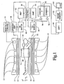
- FIGURE 1 is a diagrammatic illustration of a magnetic resonance apparatus in accordance with aspects of the present invention; and
- FIGURE 2 is a diagrammatic illustration of an end view of a lung coil in accordance with aspects of the present invention.
-
- With reference to FIGURE 1, a main
magnetic field control 10 controls superconducting orresistive magnets 12 such that a substantially uniform, temporally constant main magnetic field B0 is created along a z axis through anexamination region 14. Acouch 16 suspends asubject 18 to be examined at least partially within the examination region (i.e., so that a region of interest is in the examination region). In a preferred embodiment, thecouch 16, and consequently thesubject 18, is movable so that thesubject 18 may be selectively placed in and removed from theexamination region 14. - A magnetic resonance echo means operated under the control of a
sequence control circuit 20 applies a series of radio frequency (RF) and magnetic field gradient pulses to invert or excite magnetic spins, induce magnetic resonance, refocus magnetic resonance, manipulate magnetic resonance, spatially and otherwise encode the magnetic resonance, to saturate spins, and the like to generate magnetic resonance imaging and spectroscopy sequences. - More specifically, a gradient coil assembly selectively creates magnetic gradients in the main magnetic field across the examination region. Gradient
current amplifiers 30 apply electrical current pulses to selected ones or pairs of whole-body gradient coils 32. Preferably, the whole-body gradient coils 32 are self shielded gradient coils for producing magnetic gradients along three mutually orthogonal axes, x, y, and z. - A transmit/receive (T/R) switch 40 under the control of the
sequence control circuit 20 electronically switches a whole-body RF coil 42 between transmit and receive modes. In the transmit mode, a RF transmitter 44 (preferably a digital transmitter) is electronically connected and transmits RF pulses or pulse packets to a whole-body RF coil 42 to excite resonance in the 1H species. A typical RF pulse is composed of a packet of immediately continuous pulse segments of short duration which taken together achieve a selected magnetic resonance manipulation. The RF pulses are used to saturate, excite resonance, invert magnetization, refocus resonance, or manipulate resonance in selected portions of theexamination region 14. The whole-body RF coil 42 is tuned to the 1H resonance frequency and attached PIN diodes 46 (shown in FIGURE 2) are selectively biased to enable and disable it. The PIN diodes are biased by a selectively applied DC potential to open and closed states to open or close connections between coil segments and/or between the coil segments and ground. - For whole-body applications, the signals from excited 1H dipoles as they relax are picked up by the whole-
body RF coil 42. In the receive mode, the T/R switch 40 electronically connects the whole-body RF coil 42 to a channel of a receiver 50 (preferably a digital multi-channel receiver) via apreamplifier 52. Thesequence control circuit 20 controls thegradient pulse amplifiers 30 and theRF transmitter 44 to generate any of a plurality of multiple echo sequences, such as echo-planar imaging, echo-volume imaging, gradient and spin echo imaging, fast spin echo imaging, and the like. For the selected sequence, thereceiver 50 receives one or more resonance signals following each RF excitation pulse. Ultimately, the received RF signals are demodulated and reconstructed into an image representation by areconstruction processor 60 which applies a two-dimensional Fourier transform or other appropriate reconstruction algorithm. The image may represent a planar slice through the patient, an array of parallel planar slices, a three-dimensional volume, or the like. The image is then stored in animage memory 62 where it may be accessed by a display, such as avideo monitor 64 which provides a human viewable display of the resultant image. - With reference to FIGURE 2 and continuing reference to FIGURE 1, an
insertable lung coil 70 is utilized for imaging of the subject's 18 lungs. In a preferred embodiment, the subject 18 and thelung coil 70 rest on thecouch 16 such that the subject's 18 lungs are positioned in thelung coil 70. With arms raised behind the head, the subject 18 is in a better position to have thelung coil 70 arranged high enough for full coverage of the lungs. Thelung coil 70 is formed from upper andlower sections lung coil 70 is splitable at junction 72 and opens about ahinge 74. Additionally, thelung coil 70 is fitted with a number of 1H traps, in the illustrated embodiment parallelresonant circuits 76 including a parallel connected inductor capacitor pair, that make thelung coil 70 transparent to the transmit field of the whole-body RF coil 42. In one embodiment, the traps are tuned to present open, signal blocking circuits at the whole body coil frequency and closed, signal passing circuits at the lung coil frequency. Optionally, other appropriate traps and/or circuits may be utilized that restrict thelung coil 70 from carrying signal of the frequency of the whole-body RF coil 42. - Optionally, the two
sections break 74. The coil portions on the top and bottom halves can be connected with pins and sockets, electro magnetically coupled by the tank circuits, capacitively coupled, or the like. On the other hand, thelung coil 70 may be made out of a single nonsplitable piece for appropriate applications. - In the preferred embodiment, the
lung coil 70 is a birdcage coil (or other appropriate type coil) with rigid upper andlower sections lower sections lung coil 70 with respect to surrounding structures and the subject 18. However, either or bothsections subjects 18 of differing sizes. - Like the whole-
body coil 42, thelung coil 70 is connected via a transmit/receive (T/R)switch 80, controlled by thesequence control circuit 20, to aRF transmitter 82 and apreamplifier 84 that feeds a second channel of the receiver 50 (optionally two separate receivers are employed). Thelung coil 70 is tuned to an alternate resonance frequency for a species other than 1H. In a preferred embodiment, thelung coil 70 is tuned to the resonance frequency for a hyper-polarized gas such as 129Xe, 3He, or the like. In this manner, the lungs of the subject 18 being examined can be imaged when the hyper-polarized gas is introduced. In particular, the hyper-polarized gas is imaged to generate images showing the lung cavity, absorption of the hyper-polarized gas, and the like. One advantage realized is an improved image due to the relative abundance of the resonant species (i.e. the hyper-polarized gas) as compared to the 1H present in the lung tissue. That is, the lungs are a "cavity" with inherently little tissue in which to excite resonance and generate an image. - The
sequence control circuit 20 causes a selected imaging sequence to be generated for thelung coil 70 which excites dipoles of the hyper-polarized gas in the lungs of the subject 18. Ultimately, signals generated by the dipoles as they relax are: picked-up by thelung coil 70, received and demodulated by thereceiver 50, reconstructed by theprocessor 60, and stored in theimage memory 62 for selective viewing on themonitor 64. - In operation, when the
lung coil 70 is in transmit mode currents tend to be induced in the whole-body RF coil 42 by their inductive coupling. These induced currents could, potentially, produce uncontrollable effects by forward conduction of thePIN diodes 46. Such induced currents could be carried down stream and damage preamplifiers and other downstream components. To protect against strong transmit signals from thelung coil 70 from being received by a disabled whole-body RF coil 42 despite thePIN diodes 46, the whole-body RF coil 42 is enabled. Thesequence control circuit 20 puts the T/R switch 40 into the transmit mode such that thepreamplifier 52 is not connected to the whole-body RF coil 42. Optionally, traps and/or band pass filters 48 that pass the 1H resonant frequency signal while restricting other frequencies are connected between the wholebody RF coil 42 and the downstream components, such as thepreamplifier 52. - This results in a small, but not negligible, capacitance being inductively coupled into the
lung coil 70. Thelung coil 70 is tuned, viaadjustable capacitor 71 or other appropriate tuning circuit, with the whole-body RF coil 42 enabled in order to account for the effective capacitance from the whole-body RF coil and achieve optimum performance. To maintain the correct tuning when the lung coil is in the receive mode, the whole-body RF coil 42 is enabled during the receiving operation of thelung coil 70. Additionally, when thelung coil 70 is in receive mode, the whole-body RF coil 42 is also in receive mode to protect the second channel of the receiver 50 (the channel connected to the lung coil 70) from incoming noise from theRF transmitter 44. - One advantage of the illustrated lung coil for imaging hyper-polarized gas in an MRI scanner is that it simultaneously images at least two different species. Another advantage is that the insertable RF coil can be installed into an MRI apparatus having a built-in RF body coil tuned to hydrogen and work with, rather than in spite of, the built-in RF body coil. Another advantage is that it provides an alternately tuned coil of sufficient size for imaging a subject's lungs. Another advantage is that it protects downstream reception components from damage. Another advantage resides in its improved performance for lung imaging.
- While preferred embodiments above have been described with reference to a lung coil for imaging hyper-polarized gas, the invention herein is also amenable to other applications. The invention may be utilized to image other anatomical regions and/or other species. For example, a head coil could excite a hyper-polarized gas, such as 129Xe, dissolved in a subject's blood for brain imaging studies. The coil could be tuned to the resonant frequency for 31P to study metabolic processes of, for example, the heart or other muscle of interest.
- Additionally, while illustrated for use in a central bore horizontal field type MRI apparatus, the invention is also applicable to open geometry MRI systems having an examination region defined between opposing pole pieces that are connected by a ferrous flux return path. Open geometry MRI systems provide certain advantages particularly in the case of interventional MRI applications.
Claims (7)
- Magnetic resonance imaging apparatus comprising: a main magnet (12) for generating a substantially uniform temporally constant main magnetic field through an examination region (14) defined by the main magnet (12); a couch (16) for suspending a region of interest of a subject (18) to be examined in the examination region (14); a gradient coil assembly (32) for generating substantially linear magnetic gradients in the main magnetic field across the examination region (14); a body RF coil (42) situated at a periphery of the examination region (14) tuned to a first Larmor frequency corresponding to hydrogen nuclei; an insertable RF coil (70) positioned inside the body RF coil (42) adjacent thereto, the insertable RF coil (70) being tuned to a second Larmor frequency corresponding to a non-hydrogen nuclei; characterized in that the body coil (42) is selectively enabled and disabled; the insertable RF coil (70) is tuned while the body RF coil (42) is enabled; a first transmitter (44) is provided for transmitting RF signals at the first Larmor frequency; a first switch (40) that electronically switches the body RF coil (42) between (i) a transmit mode in which the body RF coil (42) is electronically connected to the first transmitter (44) for exciting resonance in hydrogen nuclei disposed within the examination region (14), and, (ii) a receive mode in which the body RF coil (42) is electronically connected to a first receiver channel for receiving and demodulating magnetic resonance signals emitted from excited hydrogen nuclei as they relax; a second transmitter (82) is provided for transmitting RF signals at the second Larmor frequency; a second switch (80) that electronically switches the insertable RF coil (70) between (i) a transmit mode in which the insertable RF coil (70) is electronically connected to the second transmitter (82) for exciting resonance in non-hydrogen nuclei disposed within the examination region (14), and (ii) a receive mode in which the insertable RF coil (70) is electronically connected to a second receiver channel for receiving and demodulating magnetic resonance signals emitted from excited non-hydrogen nuclei as they relax; a reconstruction processor (60) is connected with the first and second receiver channels for reconstructing the magnetic resonance signals from excited hydrogen and non-hydrogen nuclei into image representations; and a sequence control circuit (20) is provided which operates the first and second switches (40,80) such that the body RF coil (42) is in the transmit mode when the insertable RF coil (70) is in the transmit mode, and the body RF coil (42) is in the receive mode when the insertable RF coil (70) is in the receive mode.
- Magnetic resonance imaging apparatus as claimed in claim 1, wherein the non-hydrogen nuclei is the nuclei of a hyper-polarized gas.
- Magnetic resonance imaging apparatus as claimed in claim 1 or 2, wherein the insertable RF coil (70) is a lung coil for imaging the subject's (18) lungs.
- Magnetic resonance imaging apparatus as claimed in any one of claims 1 to 3, wherein the body RF coil (42) includes at least one circuit (48) which restricts the body RF coil (42) from supporting the second Larmor frequency.
- A method of magnetic resonance imaging comprising:characterized in that(a) introducing hyper-polarized gas into a region of interest of a subject being examined;(b) placing the region of interest of the subject being examined in a substantially uniform temporally constant main magnetic field;(c) generating magnetic gradients in the main magnetic field across the region of interest;(d) transmitting into the region of interest, via a first tuned coil (42), RF signals having a frequency for exciting resonance in hydrogen dipoles;(e) receiving, via the first tuned coil, signals emitted from the region of interest by resonating hydrogen dipoles;(f) transmitting into the region of interest, via a second tuned coil (70) whose tuning accounts for a capacitive coupling with the first tuned coil, RF signals having a frequency for exciting resonance in hyper-polarized gas dipoles;(g) receiving, via the second tuned coil, signals emitted from the region of interest by resonating hyper-polarized gas dipoles; and,(h) reconstructing human viewable images of the region of interest from the received signals,
the second tuned coil is tuned to the resonance frequency for the hyper-polarized gas dipoles while the first tuned coil is enabled, the first tuned coil being switched in a transmit mode when the second tuned coil is switched in a transmit mode, and the first tuned coil being switched in a receive mode when the second tuned coil is switched in a receive mode,
the first and second tuned coils each being connected to a respective transmitter for exciting resonance in respective nuclei when being in the transmit mode, and
the first and second tuned coils each being connected to a respective receiver channel for receiving and demodulating magnetic resonance signals when being in the receive mode. - A method as claimed in claim 5, wherein the region of interest is the subject's lungs.
- A method as claimed in claim 5 or 6, wherein the hyper-polarized gas is one of xenon 129 and helium three.
Applications Claiming Priority (2)
| Application Number | Priority Date | Filing Date | Title |
|---|---|---|---|
| US09/075,117 US6211677B1 (en) | 1998-05-08 | 1998-05-08 | Lung coil for imaging hyper-polarized gas in an MRI scanner |
| US75117 | 1998-05-08 |
Publications (3)
| Publication Number | Publication Date |
|---|---|
| EP0955554A2 EP0955554A2 (en) | 1999-11-10 |
| EP0955554A3 EP0955554A3 (en) | 2001-07-18 |
| EP0955554B1 true EP0955554B1 (en) | 2005-05-11 |
Family
ID=22123663
Family Applications (1)
| Application Number | Title | Priority Date | Filing Date |
|---|---|---|---|
| EP99303544A Expired - Lifetime EP0955554B1 (en) | 1998-05-08 | 1999-05-06 | Multi-frequency magnetic resonance imaging |
Country Status (3)
| Country | Link |
|---|---|
| US (1) | US6211677B1 (en) |
| EP (1) | EP0955554B1 (en) |
| DE (1) | DE69925193T2 (en) |
Cited By (1)
| Publication number | Priority date | Publication date | Assignee | Title |
|---|---|---|---|---|
| CN101067649B (en) * | 2006-05-05 | 2011-02-09 | 高质电动有限公司 | Active decoupling of mri RF transmit coils |
Families Citing this family (21)
| Publication number | Priority date | Publication date | Assignee | Title |
|---|---|---|---|---|
| JP3705973B2 (en) * | 1999-11-19 | 2005-10-12 | ジーイー・メディカル・システムズ・グローバル・テクノロジー・カンパニー・エルエルシー | RF coil and magnetic resonance imaging apparatus |
| US6552544B2 (en) * | 2001-04-05 | 2003-04-22 | Varian, Inc. | Detunable coil assembly and method of detuning RF coil for MRI |
| GB0110392D0 (en) * | 2001-04-27 | 2001-06-20 | Oxford Instr Plc | Method and apparatus for magnetic resonance imaging |
| US6791321B2 (en) * | 2002-06-18 | 2004-09-14 | Koninklijke Philips Electronics N.V. | Birdcage coils for simultaneous acquisition of spatial harmonics |
| US6973162B2 (en) * | 2003-10-30 | 2005-12-06 | General Electric Company | MR/X-ray scanner having rotatable anode |
| US6940282B2 (en) * | 2003-12-19 | 2005-09-06 | General Electric Company | Switchable transmit array coil |
| DE102004012248A1 (en) * | 2004-03-12 | 2005-09-29 | Siemens Ag | Magnetic resonance tomography device with improved connection of supply lines when using insert gradient coils |
| US20060255804A1 (en) * | 2005-05-13 | 2006-11-16 | General Electric | Three concentric coil array |
| US20070190663A1 (en) * | 2005-08-12 | 2007-08-16 | Lee Ray F | System and method for using polarized or hyperpolarized contrast agent to perform parallel magnetic resonance imaging of a sample |
| CN101553168A (en) * | 2006-10-03 | 2009-10-07 | 杜克大学 | Systems and methods for assessing pulmonary gas transfer using hyperpolarized 129XE MRI |
| EP2223134A1 (en) * | 2007-12-13 | 2010-09-01 | Koninklijke Philips Electronics N.V. | Dual tuned volume coils adapted to provide an end ring mode |
| CN201207079Y (en) * | 2007-12-29 | 2009-03-11 | 西门子(中国)有限公司 | Air pressure fixed coil |
| WO2011103138A2 (en) | 2010-02-16 | 2011-08-25 | Duke University | Systems, methods, compositions and devices for in vivo magnetic resonance imaging of lungs using perfluorinated gas mixtures |
| DE102010025919A1 (en) * | 2010-07-02 | 2012-01-05 | Siemens Aktiengesellschaft | Magnetic resonance imaging system has coil system with upper section and lower section, where upper section is arranged above opening for inclusion of object under examination |
| DE102013205817A1 (en) * | 2013-04-03 | 2014-10-09 | Siemens Aktiengesellschaft | Transmission arrangement for a tomograph |
| US10591561B2 (en) | 2014-11-11 | 2020-03-17 | Hyperfine Research, Inc. | Pulse sequences for low field magnetic resonance |
| EP3261534B1 (en) * | 2015-02-27 | 2022-01-19 | Koninklijke Philips N.V. | Magnetic resonance examination system with a moveable patient carrier |
| CN105662415A (en) * | 2016-03-03 | 2016-06-15 | 哈尔滨医科大学 | Multi-nucleus magnetic resonance imaging system |
| CN107884732A (en) * | 2016-09-30 | 2018-04-06 | 西门子(深圳)磁共振有限公司 | MR imaging apparatus, radio-frequency coil and its manufacture method |
| TW202012951A (en) | 2018-07-31 | 2020-04-01 | 美商超精細研究股份有限公司 | Low-field diffusion weighted imaging |
| WO2021108216A1 (en) | 2019-11-27 | 2021-06-03 | Hyperfine Research, Inc. | Techniques for noise suppression in an environment of a magnetic resonance imaging system |
Family Cites Families (16)
| Publication number | Priority date | Publication date | Assignee | Title |
|---|---|---|---|---|
| US4930510A (en) | 1986-11-24 | 1990-06-05 | Picker International, Inc. | Parameterization for CT blood flow mapping with xenon gas enhancement |
| US4793357A (en) | 1986-11-24 | 1988-12-27 | Picker International, Inc. | CT blood flow mapping with xenon gas enhancement |
| US5024230A (en) | 1988-11-23 | 1991-06-18 | Picker International, Inc. | Dual flow/lambda display for xenon enhanced tomography |
| US5256972A (en) * | 1990-01-30 | 1993-10-26 | Elscint, Ltd. | Body coil decoupling circuit |
| US5075624A (en) * | 1990-05-29 | 1991-12-24 | North American Philips Corporation | Radio frequency quadrature coil construction for magnetic resonance imaging (mri) apparatus |
| GB2261516B (en) * | 1991-11-08 | 1995-07-05 | Marconi Gec Ltd | Magnetic resonance methods and apparatus |
| US5365173A (en) | 1992-07-24 | 1994-11-15 | Picker International, Inc. | Technique for driving quadrature dual frequency RF resonators for magnetic resonance spectroscopy/imaging by four-inductive loop over coupling |
| EP0695947B1 (en) * | 1994-08-03 | 2001-11-14 | Philips Patentverwaltung GmbH | MR method for determining the distribution of nuclear magnetization with a surface coil arrangement |
| US5628327A (en) * | 1994-12-15 | 1997-05-13 | Imarx Pharmaceutical Corp. | Apparatus for performing biopsies and the like |
| US5680047A (en) | 1995-08-11 | 1997-10-21 | Picker International, Inc. | Multipl-tuned radio frequency coil for simultaneous magnetic resonance imaging and spectroscopy |
| US5617859A (en) * | 1995-10-02 | 1997-04-08 | General Electric Company | Apparatus and methods for magnetic resonance (MR) imaging of cavities using fluids polarized at low temperatures |
| DE19624682C2 (en) * | 1996-06-20 | 1998-04-16 | Siemens Ag | Transmitting and / or receiving device for a diagnostic magnetic resonance device |
| US5783943A (en) * | 1996-11-27 | 1998-07-21 | Mastandrea, Jr.; Nicholas J. | Method and apparatus for positioning an insert gradient coil within an examination region of a magnetic resonance imaging apparatus |
| US5998999A (en) * | 1996-12-12 | 1999-12-07 | Picker International, Inc. | Volume RF coils with integrated high resolution focus coils for magnetic resonance imaging |
| US5990681A (en) * | 1997-10-15 | 1999-11-23 | Picker International, Inc. | Low-cost, snap-in whole-body RF coil with mechanically switchable resonant frequencies |
| US6081120A (en) * | 1998-05-20 | 2000-06-27 | Shen; Gary G | Universal-multi-layered, multi-tuned RF probe for MRI and MRS |
-
1998
- 1998-05-08 US US09/075,117 patent/US6211677B1/en not_active Expired - Lifetime
-
1999
- 1999-05-06 DE DE69925193T patent/DE69925193T2/en not_active Expired - Lifetime
- 1999-05-06 EP EP99303544A patent/EP0955554B1/en not_active Expired - Lifetime
Cited By (1)
| Publication number | Priority date | Publication date | Assignee | Title |
|---|---|---|---|---|
| CN101067649B (en) * | 2006-05-05 | 2011-02-09 | 高质电动有限公司 | Active decoupling of mri RF transmit coils |
Also Published As
| Publication number | Publication date |
|---|---|
| EP0955554A3 (en) | 2001-07-18 |
| DE69925193D1 (en) | 2005-06-16 |
| DE69925193T2 (en) | 2006-02-23 |
| EP0955554A2 (en) | 1999-11-10 |
| US6211677B1 (en) | 2001-04-03 |
Similar Documents
| Publication | Publication Date | Title |
|---|---|---|
| EP0955554B1 (en) | Multi-frequency magnetic resonance imaging | |
| US5998999A (en) | Volume RF coils with integrated high resolution focus coils for magnetic resonance imaging | |
| US6316941B1 (en) | Open view quadrature birdcage coil | |
| US5664568A (en) | Split-top, neck and head vascular array for magnetic resonance imaging | |
| US6906518B2 (en) | RF coil system for magnetic resonance imaging apparatus | |
| EP0932048B1 (en) | Localized shim coil for use in magnetic resonance imaging system | |
| US5898306A (en) | Single circuit ladder resonator quadrature surface RF coil | |
| Kneeland et al. | High-resolution MR imaging with local coils. | |
| US6650118B2 (en) | RF coil system for an MR apparatus | |
| US5280248A (en) | Biplanar RF coil for magnetic resonance imaging systems | |
| US7945308B2 (en) | Systems, methods and apparatus for an endo-rectal receive-only probe | |
| US8981777B2 (en) | Spine coil array | |
| JP2001137215A (en) | Characteristic uncoupled sandwich solenoid array coil | |
| US7906966B1 (en) | Quadrature foot coil antenna for magnetic resonance imaging | |
| US10274560B2 (en) | Use of a plurality of TX coils | |
| US4928064A (en) | Hybrid surface coils | |
| US9041398B2 (en) | RF antenna for MRI with a removable conductor | |
| JP5020631B2 (en) | Method for performing open peripheral vascular coil and peripheral vascular imaging | |
| US20050107684A1 (en) | Elevated Endring Birdcage Antenna For MRI Applications | |
| Matsumoto et al. | A composite resonator assembly suitable for EPR/NMR coregistration imaging | |
| US20130123612A1 (en) | Mrt surface coil array | |
| RU2574348C2 (en) | Radio-frequency antenna for magnetic-resonance imaging with removable conductor | |
| WO2003016936A1 (en) | Imaging apparatus and method | |
| WO2020178766A1 (en) | Mri apparatus and method adapted for changing the static magnetic field b0 from a first to a second value |
Legal Events
| Date | Code | Title | Description |
|---|---|---|---|
| PUAI | Public reference made under article 153(3) epc to a published international application that has entered the european phase |
Free format text: ORIGINAL CODE: 0009012 |
|
| AK | Designated contracting states |
Kind code of ref document: A2 Designated state(s): DE FR NL |
|
| AX | Request for extension of the european patent |
Free format text: AL;LT;LV;MK;RO;SI |
|
| RAP1 | Party data changed (applicant data changed or rights of an application transferred) |
Owner name: MARCONI MEDICAL SYSTEMS, INC. |
|
| PUAL | Search report despatched |
Free format text: ORIGINAL CODE: 0009013 |
|
| AK | Designated contracting states |
Kind code of ref document: A3 Designated state(s): AT BE CH CY DE DK ES FI FR GB GR IE IT LI LU MC NL PT SE |
|
| AX | Request for extension of the european patent |
Free format text: AL;LT;LV;MK;RO;SI |
|
| 17P | Request for examination filed |
Effective date: 20020104 |
|
| AKX | Designation fees paid |
Free format text: DE FR NL |
|
| RAP1 | Party data changed (applicant data changed or rights of an application transferred) |
Owner name: PHILIPS MEDICAL SYSTEMS (CLEVELAND), INC. |
|
| RAP1 | Party data changed (applicant data changed or rights of an application transferred) |
Owner name: KONINKLIJKE PHILIPS ELECTRONICS N.V. |
|
| 17Q | First examination report despatched |
Effective date: 20040316 |
|
| GRAP | Despatch of communication of intention to grant a patent |
Free format text: ORIGINAL CODE: EPIDOSNIGR1 |
|
| GRAS | Grant fee paid |
Free format text: ORIGINAL CODE: EPIDOSNIGR3 |
|
| GRAA | (expected) grant |
Free format text: ORIGINAL CODE: 0009210 |
|
| AK | Designated contracting states |
Kind code of ref document: B1 Designated state(s): DE FR NL |
|
| PG25 | Lapsed in a contracting state [announced via postgrant information from national office to epo] |
Ref country code: NL Free format text: LAPSE BECAUSE OF FAILURE TO SUBMIT A TRANSLATION OF THE DESCRIPTION OR TO PAY THE FEE WITHIN THE PRESCRIBED TIME-LIMIT Effective date: 20050511 |
|
| REF | Corresponds to: |
Ref document number: 69925193 Country of ref document: DE Date of ref document: 20050616 Kind code of ref document: P |
|
| NLV1 | Nl: lapsed or annulled due to failure to fulfill the requirements of art. 29p and 29m of the patents act | ||
| PLBE | No opposition filed within time limit |
Free format text: ORIGINAL CODE: 0009261 |
|
| STAA | Information on the status of an ep patent application or granted ep patent |
Free format text: STATUS: NO OPPOSITION FILED WITHIN TIME LIMIT |
|
| ET | Fr: translation filed | ||
| 26N | No opposition filed |
Effective date: 20060214 |
|
| REG | Reference to a national code |
Ref country code: DE Ref legal event code: R082 Ref document number: 69925193 Country of ref document: DE Representative=s name: MEISSNER, BOLTE & PARTNER GBR, DE |
|
| REG | Reference to a national code |
Ref country code: DE Ref legal event code: R082 Ref document number: 69925193 Country of ref document: DE Representative=s name: MEISSNER BOLTE PATENTANWAELTE RECHTSANWAELTE P, DE Effective date: 20140328 Ref country code: DE Ref legal event code: R082 Ref document number: 69925193 Country of ref document: DE Representative=s name: MEISSNER, BOLTE & PARTNER GBR, DE Effective date: 20140328 Ref country code: DE Ref legal event code: R081 Ref document number: 69925193 Country of ref document: DE Owner name: KONINKLIJKE PHILIPS N.V., NL Free format text: FORMER OWNER: KONINKLIJKE PHILIPS ELECTRONICS N.V., EINDHOVEN, NL Effective date: 20140328 |
|
| REG | Reference to a national code |
Ref country code: FR Ref legal event code: CD Owner name: KONINKLIJKE PHILIPS N.V., NL Effective date: 20141126 Ref country code: FR Ref legal event code: CA Effective date: 20141126 |
|
| REG | Reference to a national code |
Ref country code: FR Ref legal event code: PLFP Year of fee payment: 17 |
|
| PGFP | Annual fee paid to national office [announced via postgrant information from national office to epo] |
Ref country code: FR Payment date: 20150529 Year of fee payment: 17 |
|
| PGFP | Annual fee paid to national office [announced via postgrant information from national office to epo] |
Ref country code: DE Payment date: 20150730 Year of fee payment: 17 |
|
| REG | Reference to a national code |
Ref country code: DE Ref legal event code: R119 Ref document number: 69925193 Country of ref document: DE |
|
| REG | Reference to a national code |
Ref country code: FR Ref legal event code: ST Effective date: 20170131 |
|
| PG25 | Lapsed in a contracting state [announced via postgrant information from national office to epo] |
Ref country code: DE Free format text: LAPSE BECAUSE OF NON-PAYMENT OF DUE FEES Effective date: 20161201 Ref country code: FR Free format text: LAPSE BECAUSE OF NON-PAYMENT OF DUE FEES Effective date: 20160531 |