EP0955402B1 - A flat bed knitting machine having a transfer mechanism and a transferring method thereby - Google Patents
A flat bed knitting machine having a transfer mechanism and a transferring method thereby Download PDFInfo
- Publication number
- EP0955402B1 EP0955402B1 EP99303588A EP99303588A EP0955402B1 EP 0955402 B1 EP0955402 B1 EP 0955402B1 EP 99303588 A EP99303588 A EP 99303588A EP 99303588 A EP99303588 A EP 99303588A EP 0955402 B1 EP0955402 B1 EP 0955402B1
- Authority
- EP
- European Patent Office
- Prior art keywords
- needle
- bed
- stitch loop
- transfer
- transfer member
- Prior art date
- Legal status (The legal status is an assumption and is not a legal conclusion. Google has not performed a legal analysis and makes no representation as to the accuracy of the status listed.)
- Expired - Lifetime
Links
Images


Classifications
-
- D—TEXTILES; PAPER
- D04—BRAIDING; LACE-MAKING; KNITTING; TRIMMINGS; NON-WOVEN FABRICS
- D04B—KNITTING
- D04B7/00—Flat-bed knitting machines with independently-movable needles
- D04B7/20—Flat-bed knitting machines with independently-movable needles with provision for changing the fabric construction, e.g. from plain to rib-loop fabric
-
- D—TEXTILES; PAPER
- D04—BRAIDING; LACE-MAKING; KNITTING; TRIMMINGS; NON-WOVEN FABRICS
- D04B—KNITTING
- D04B15/00—Details of, or auxiliary devices incorporated in, weft knitting machines, restricted to machines of this kind
- D04B15/02—Loop-transfer points
Definitions
- the present invention relates to a flat bed knitting machine wherein an upper auxiliary bed having transfer members is provided on at least one needle bed of a pair of lower needle beds, one in the front and the other in the rear.
- the present invention relates to a flat bed knitting machine that can reliably make a needle advance into a stitch loop when transferring is made from an upper auxiliary bed to a lower needle bed, and a transferring method thereby.
- a pair of lower needle beds having needle grooves in the top thereof are arranged to oppose each other, one in the front and the other in the rear, and an upper bed is provided on at least one of these lower needle beds.
- a transfer member such as a transfer jack or a needle having a transfer wing is slidably held in each groove of the upper bed.
- a stitch loop can be transferred between the pair of lower needle beds or between a lower needle bed and an upper bed.
- a stitch loop formed by needles of a lower needle bed is transferred onto a transfer member of an upper bed, then the front and rear needle beds are racked in the longitudinal direction.
- the stitch loop held on the transfer jack is transferred onto a needle of the lower needle bed.
- the stitch loop is transferred onto a needle other than the needle that originally held the stitch loop.
- the transfer member when seen from a side, at the time of transferring, the transfer member is in a low position in which the transfer member overlaps with a sinker plate provided at the top end of the needle bed.
- the flat bed knitting machine is provided with a mechanism for retracting the upper bed, at the time of racking, into a position wherein the upper bed will not interfere with the sinker plate. Provision of such a retracting mechanism, however, makes the entire mechanism more complex.
- the upper bed is withdrawn upward while the stitch loop is held on the transfer member, it may cause troubles such as stretching and breakage of a stitch loop.
- the space for advancement of a needle is narrowed down, posing more difficult conditions.
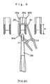
- the stitch loop 201 held on the transfer member will be tilted sidewise as shown in Fig. 9.
- the needle 205 To receive the stitch loop 201 onto the hook of the needle 205 from the transfer member 203, the needle 205 must reliably advance between a pair of loop holders 207a, 207b of the transfer member 203 and into the loop 201 held on these loop holders. To make the needle 205 reliably advance into the stitch loop 201, it is sufficient to give a large space between a loop top 201a and a loop bottom 201b on the transfer member 203.
- EP310730 discloses a rectilineal knitting machine equipped with two knitting lines of normal needles and two other auxiliary knitting lines for side transfer in the same knitting head. The auxiliary knitting lines are actuated by corresponding cams to move in a fully automatic mode.
- EP594169 discloses a flat knitting machine comprising a carriage and a transferring cam moving adversely at any position on a needle bed to reduce the size of a transferring mechanism and to arrange the transferring mechanism at a dead space.
- a large number of needles having a hook rear and a hook face are held on each of a first lower needle bed and a second lower needle bed in such a way that these needles can be advanced and retracted, the first needle bed and the second needle bed are arranged to oppose each other with a trick gap between them, the center line of said trick gap is defined as the trick gap center line, said first lower needle bed and said second lower needle bed can be racked relative to each other, and an upper bed holding a large number of transfer members is provided in such a way that they can be advanced and retracted over at least one of the first and second lower needle beds.
- the flat bed knitting machine is characterized in that to transfer a stitch loop held on a transfer member of the upper bed to a receiving needle of the first lower needle bed, the flat bed knitting machine is further provided with a transfer member control means for shifting first the transfer member away from the receiving needle and then advancing the transfer member towards the receiving needle, and a needle control means for advancing the receiving needle towards the transfer member upon or after start of the advancement of said transfer member towards the receiving needle.
- the flat bed knitting machine is further characterized in that said transfer member control means has a transfer member control cam reciprocating over the upper bed, that said transfer member control cam comprises a first cam means for advancing first the stitch loop held on said transfer member to a position beyond the trick gap center line and then retracting the stitch loop, and a second cam means for positioning first the stitch loop held on said transfer member in a position short of the trick gap center line and then advancing the stitch loop, and that said needle control means has a means for, in association with said first cam means, advancing the hook rear of said receiving needle to a position where the hook rear is in the stitch loop when said stitch loop is in a position beyond the trick gap center line and advancing the hook face of said receiving needle into the stitch loop when the stitch loop is retracted, and a means for, in association with said second cam means, advancing the hook rear of said receiving needle to a position where the hook rear is in the stitch loop when said stitch loop is retracted to a position short of the trick gap center line and advancing
- said first cam means and said second cam means comprise a single continuous cam groove formed in the transfer member control cam.
- the transferring method using the flat bed knitting machine according to the present invention is characterized in that when transferring is made from a transfer member of an upper bed holding a stitch loop to a receiving needle of a lower needle bed, a hook rear of the needle is advanced into the stitch loop, and corresponding to this, the transfer member is shifted to shift the stitch loop onto a hook rear of the needle, and next, the hook face of the needle is advanced into the stitch loop, and corresponding to this, the transfer member is shifted to shift the stitch loop onto the hook face.
- a stitch loop held on the transfer member is shifted to the hook rear side of the needle or side more distant from the needle and the hook rear is advanced into the stitch loop.
- the transfer member is shifted in the reverse direction, namely, to the hook face side of the needle, then the needle is advanced further to advance the hook face into the stitch loop.
- the first step of shifting the stitch loop towards the hook rear makes it easier for the hook rear to advance into the stitch loop.
- the step of shifting the stitch loop towards the needle makes it easier for the stitch loop to go beyond the hook face into the hook.
- transferring can be made reliably from a transfer member onto a needle of a lower needle bed and yam is not strained.
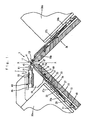
- Fig. 1 is a vertical sectional view of an important part of the flat bed knitting machine of the embodiment.
- the flat bed knitting machine 1 is provided with a pair of a lower needle bed 3a (front bed 3a) and a lower needle bed 3b (rear bed 3b) arranged to oppose to each other, one in the front and the other in the rear, and a transfer jack bed 7, an upper bed is arranged above the front bed 3a.
- the transfer jack bed 7 holds transfer jacks 5 being transfer members.
- the beds 3a, 3b are provided with plural grooves in the top of the respective bases 9.
- a needle plate 11 is set up in each of these grooves and a space between two adjacent needle plates 11, 11 is used as a needle groove 13.
- a needle 15 is held in each needle groove 13 in such a way that the needle can be moved towards and away from a trick gap 17 formed between the front and rear needle beds.
- the rear bed 3b can be shifted in its longitudinal direction by a driving means not illustrated (hereinafter this shift is referred to as racking).
- the transfer jack bed 7 is provided with grooves 21 formed at the same pitch with the pitch of the needles of the front bed 3a and the rear bed 3b. Each of these grooves 21 holds a transfer jack being a transfer member in such a way that the transfer jack 5 can be advanced and retracted, and the transfer jack bed 7 can be shifted sidewise relatively to the front bed 3a and the rear bed 3b. In the flat bed knitting machine 1 of the embodiment, transfer can be made between both the front and rear beds 3a, 3b, and between the transfer jack bed 7 and any one of both the front and rear beds 3a, 3b.
- a concave 23 is formed in the rear end of the needle 15 held in the needle groove 13, and this concave 23 and a convex 25 provided on the needle jack 27 fit with each other.
- a butt 29 formed on the needle jack 27 and a butt 33 formed on the slider 31 are operated by cams 37a, 37b, 39a, 39b provided on these carriages 35a, 35b to effect knitting. Compound needles are used in this knitting. However, latch needles may be used.
- the top end of the slider 31 is formed by overlapping two thin plates with each other.
- the hook 41 will push and divide the slider 31 into two prongs, and a shoulder 45 of the slider 31 will hold a stitch loop to guide it into a transfer position.
- Each needle 15 is held in a needle groove 13 by a metal plate 47 fixed on a needle bed along the longitudinal direction thereof.
- the rear end of the needle jack 27 is elastically energized by the bottom of the needle groove 13 so that the butt 29 of the needle jack 27 is energized to come out of the needle groove 13.
- the needle jack 27 is held in the needle groove by a wire 49 mounted in the longitudinal direction of the needle bed.
- a select jack 51 is set above the needle jack 27, and when the select jack 51 is pressed by a presser mounted on the carriage 35a or 35b in such a way that the select jack 51 is sunk into the needle groove 13, the butt 29 of the needle jack 27 will not engage with the knitting cam 39a or 39b of the carriage 35a or 35b and be sunk into a rest position.
- a sinker plate 53 is provided between needles.
- Needle plates 11 set up on the front bed 3a are selected at fixed intervals to be extended upward and their extensions 55 are used as supports of the transfer jack bed 7.
- Transfer jacks 5 are held in respective grooves 21 of the transfer jack bed 7 and retained by a metal plate 59.
- the grooves 21 are set at the same pitch with those of the needle grooves 13 of both the front and rear beds 3a, 3b.
- a loop holder 61 is formed at the top end of the transfer jack 5, and an advancement/retraction control butt 63 is formed at the rear end thereof. When the butt 63 engages with a transfer jack cam 65 mounted on the carriage 35a, the transfer jack 5 will be advanced towards or retracted from the trick gap 17 located between both the front and rear needle beds.
- 67 denotes a wire mounted in the longitudinal direction of the needle bed to hold the sinker plate 53.
- 69 is a wire that fixes the base 9 and the needle plates 11 together.
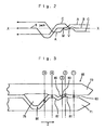
- a chain line X-X indicates the position of the trick gear center line
- a line A indicates the track of the hook face of the needle 15b of the rear bed 3b when transfer is made from the transfer jack bed 7 to the rear bed 3b
- a line B indicates the track of the loop holder 61 of the transfer jack 5 when transfer is made to the front bed 3a or the rear bed 3b.
- a line C is the track of the hook face of the needle 15a of the front bed 3a when transfer is made from the transfer jack bed 7 to the front bed 3a.
- An intersecting point V indicates the position at which the loop holder 61 of the transfer jack 5 and the hook face of the needle 15a intersect with each other.
- An intersecting point W indicates the position at which the line B and the hook face of the needle 15b intersect with each other. As clearly shown in Fig. 2, the position of the intersecting point V and that of W differ from each other in relation to the travel direction of the carriages.
- the transfer jack 5 advances and retracts in the same track when transfer is made to the front bed 3a and to the rear bed 3b.
- the tracks of the needles that receive a stitch loop differ from each other, depending on whether the receiving needle belongs to the front bed or the rear bed.
- the needle of the front bed 3a advances at an earlier timing than the needle of the rear bed 3b.
- the transfer jack 5 shifts away from the hook of the needle, and as a result of this, the loop holder of the transfer jack and the stitch loop will shift away from the hook and beyond the trick gap center line.
- the hook rear (the bottom of the hook and the part of the needle proper that starts to bend) will go beyond the bottom of the stitch loop and advances into the stitch loop.
- the transfer jack shifts towards the hook, and the hook also advances towards the stitch loop.
- the hook face (a part of the hook that is in parallel to and above the needle proper) and the loop holder 61 of the transfer jack intersect with each other. When the hook advances further, the stitch loop will be transferred onto the hook.
- the transfer jack cam 65 comprises a forward cam part 71 for advancing the transfer jack 5 towards the trick gap 17 located between the front and rear needle beds, a rear cam part 73 for retracting the transfer jack 5 from the trick gap 17, and a triangular movable cam 75.
- the forward cam part 71 contacts the rear of the butt 63
- the rear cam part 73 contacts the front of the butt 63.
- a route 80 for the butt 63 is provided between the front cam part 71 and the rear cam part 73 and between the movable cam 75 and the front cam part 71.
- a cam surface 81 is formed on the front cam part 71, and this cam surface advances the stitch loop to a position just a little ahead the position of the trick gap center line X-X (intermediate position) when transfer is made from the transfer jack bed 7 to the front bed 3a.
- a cam surface 83 is formed on the rear cam part 73, and this cam surface serves to bring the stitch loop back to the trick gap center line X-X.
- the cam surface 81 and the cam surface 83 are provided continuously in the travel direction (indicated by an arrow Z) of the carriages, and they control the transfer jack 5 when transfer is made from the transfer jack bed 7 to the front bed 3a.
- the rear cam part 73 is provided with a cam surface 85 for shifting the stitch loop to a position a little retracted from the trick gap center line X-X (retracted position).
- the forward cam part 71 is provided with a cam surface 87 for bringing the stitch loop that has been shifted to the retracted position back to the intermediate position.
- the cam surface 85 and the cam surface 87 are provided continuously in the direction of travel of the carriages, and they control the transfer jack 5 when transfer is made from the transfer jack bed 7 to the rear bed 3b.
- a pair of the cam surface 81 and the cam surface 83 and a pair of the cam surface 85 and the cam surface 87 are provided in different positions in the travel direction of the carriages.
- the cam surface 83 and the cam surface 85 are provided as a continuous one cam surface, or a continuous cam grrove in the present embodiment, it is not essential to provide them as a single cam surface or a groove.
- a unique feature of the present invention rests in the movements of a transfer jack and a needle when transfer is made from a transfer jack bed to one of the pair of lower needle beds. Therefore, in the embodiment, a case of transferring in a course of transferring a stitch loop sidewise will be described, wherein a stitch loop is transferred from the front bed 3a or the rear bed 3b to the transfer jack bed 7, then the transfer jack bed 7 is racked, and then the stitch loop is transferred back to the front bed 3a or the rear bed 3b.
- Fig. 4 shows the transfer jack 5 and the needle 15a of the front bed when the butt 53 is in the respective positions 1 through 5 of Fig. 3.
- Fig. 5 is a diagram in which the transfer jack 5 in the advanced position and the needle 15a in the lowered position 15a are schematically combined with each other.
- the stitch loop 91 in the advanced position is indicated by solid line
- the stitch loop 91 in the intermediate position is indicated by broken line.
- the stitch loop 91 is held on the transfer jack 5, next the carriages 35a, 35b travel in the direction of arrow Z and the transfer jack 5 comes to the position 1 of Fig. 3. This state is shown in step 1 of Fig. 4.
- the transfer jack 5 has advanced the stitch loop 91 to the intermediate position, and the needle 15a of the front bed 3a is standing by in the lowered position.
- the transfer jack 5 will be advanced by the cam surface 81.
- the needle 15a starts to advance.
- the stitch loop 91 takes the advanced position that is a little beyond the trick gap center line X-X located between the front and rear needle beds.
- the needle 15a advances towards the stitch loop 91.
- the hook rear 95b of the needle 15a will move along a straight line L that is parallel to the direction of advancement and retraction of the needle 15a. Under this condition, when the needle 15a advances towards the stitch loop 91, the hook rear 95b of the needle 15a will push the loop bottom 101 of the stitch loop 91.
- the stitch loop 91 is in the advanced position that is a little beyond the trick gap center line X-X.
- the transfer jack 5 is advanced by the cam surface 81, and under this condition, the needle 15a advances towards the stitch loop 91.
- the stitch loop 91 takes a position closer to the rear side of the needle 15a in comparison with the case in which the stitch loop 91 is located on the trick gap center line X-X. This means a higher chance for the stitch loop 91 to slip to the rear side of the needle 15a, and in turn, less chance of drop stitch.
- the hook rear 95b of the needle 15a when the hook rear 95b of the needle 15a is to advance into the stitch loop 91, if the transfer jack 5 is advanced and the stitch loop 91 is shifted to the rear side of the needle 15a, the hook rear 95b can easily advance into the stitch loop 91.
- the hook face 95a of the needle 15a is to advance into the stitch loop 91, if the transfer jack 5 is retracted and the stitch loop 91 is shifted to the face side of the needle 15a, the hook face 95a of the needle 15a can easily advance into the stitch loop 91.
- FIG. 6 shows the track of the butt 63 of the transfer jack 5 at the time of transfer from the transfer jack bed 7 to a needle of the rear bed 3b.
- Steps 1 through 5 of Fig. 7 show the transfer jack 5 and the needle 15b when the butt 63 is in the respective positions 1 through 5 of Fig. 6.
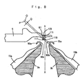
- Fig. 8 shows the transfer jack 5 in the retracted position and the needle 15b in the lowered position.
- a stitch loop 111 is indicated by full line when it is in the retracted position and by broken line when it is in the intermediate position.
- the transfer jack 5 is retracted by the cam surface 85 to the retracted position, and as a result, the stitch loop 111 shifts to the side of the front bed 3a as shown in Fig. 8.
- the stitch loop 111 is supposed to be on the trick gap center line X-X and a straight line O is drawn through the loop bottom 119 and in parallel with the advancement/retraction track of the rear bed 3b.
- the stitch loop 111 is supposed to be in the retracted position and a straight line P is drawn through the loop bottom 117 and in parallel with the advancement/retraction track of the needle of the rear bed 3b.
- the needle 15b advances further as shown in the step 4 of Fig. 7.
- the transfer jack 5 will be retracted by the movable cam 75, and the needle 15b will retract and transfer onto the needle 15b will be completed.
- the stitch loop is shifted to the hook rear side by the cam surface 81 or the cam surface 85.
- the stitch loop is restored onto the trick gap center line X-X by the cam surface 83 or the cam surface 87.
- cam surfaces 83, 87 do not have to be cams which restore a loop onto the trick gap center line X-X. It is sufficient for the cam surfaces 83, 87 to shift a stitch loop that has been shifted by the cam surface 81 or 85 in a direction opposite to the initial shift.
- a needle guide may be, as shown in the embodiment, a mechanism wherein a butt formed on a needle, a transfer jack, etc. is operated by a cam, or a mechanism wherein an individual needle is advanced and retracted by a linear motor.
- a case using an upper bed having transfer jacks as transfer members has been described.
- Transfer members on the upper bed may be needles having a transfer blade.
- the present invention is to provide a flat bed knitting machine that can transfer a stitch loop favorably without giving any excessive strain to the stitch loop when the stitch loop is to be transferred by advancing a hook of a needle of a lower needle bed into the stitch loop held on loop holders of a transfer jack, a needle, etc. provided on an upper bed, and a transferring method thereby.
Description
- The present invention relates to a flat bed knitting machine wherein an upper auxiliary bed having transfer members is provided on at least one needle bed of a pair of lower needle beds, one in the front and the other in the rear. In particular, the present invention relates to a flat bed knitting machine that can reliably make a needle advance into a stitch loop when transferring is made from an upper auxiliary bed to a lower needle bed, and a transferring method thereby.
- In a kind of flat bed knitting machines, to hold needles in needle grooves so that needles can be advanced and retracted freely, a pair of lower needle beds having needle grooves in the top thereof are arranged to oppose each other, one in the front and the other in the rear, and an upper bed is provided on at least one of these lower needle beds. A transfer member such as a transfer jack or a needle having a transfer wing is slidably held in each groove of the upper bed. A stitch loop can be transferred between the pair of lower needle beds or between a lower needle bed and an upper bed. Such a flat bed knitting machine has been disclosed in Japanese Provisional Patent Sho 63-256752.
- In the flat bed knitting machine disclosed therein, a stitch loop formed by needles of a lower needle bed is transferred onto a transfer member of an upper bed, then the front and rear needle beds are racked in the longitudinal direction. Next, the stitch loop held on the transfer jack is transferred onto a needle of the lower needle bed. As a result, the stitch loop is transferred onto a needle other than the needle that originally held the stitch loop.
- In this flat bed knitting machine, when a stitch loop held on a needle is to be transferred onto a transfer member of an upper bed, the needle is made to rise and the stitch loop is pressed to open wider by transfer wings provided on sides of the needle. A loop holder of the transfer member is made to advance into this stitch loop, then the needle is lowered. As a result, the stitch loop will be transferred from the needle onto the transfer member. On the other hand, when transferring is to be made from a transfer member of an upper bed onto a needle of a lower needle bed, a hook of the needle is made to advance into the stitch loop held on the transfer member being kept in an advanced position. Then the transfer member is made to retreat.
- In the flat bed knitting machine of Japanese Provisional Patent Sho 63-256752, when seen from a side, at the time of transferring, the transfer member is in a low position in which the transfer member overlaps with a sinker plate provided at the top end of the needle bed. The flat bed knitting machine is provided with a mechanism for retracting the upper bed, at the time of racking, into a position wherein the upper bed will not interfere with the sinker plate. Provision of such a retracting mechanism, however, makes the entire mechanism more complex. Moreover, as the upper bed is withdrawn upward while the stitch loop is held on the transfer member, it may cause troubles such as stretching and breakage of a stitch loop. In particular, when knitting is made on a knitting machine of a finer gauge or when finer stitch loops are knitted with a higher stitch density, the space for advancement of a needle is narrowed down, posing more difficult conditions.
- After transfer from a needle onto a transfer member of an upper bed, when a transferred stitch loop is racked sidewise, the
stitch loop 201 held on the transfer member will be tilted sidewise as shown in Fig. 9. To receive thestitch loop 201 onto the hook of theneedle 205 from thetransfer member 203, theneedle 205 must reliably advance between a pair ofloop holders transfer member 203 and into theloop 201 held on these loop holders. To make theneedle 205 reliably advance into thestitch loop 201, it is sufficient to give a large space between aloop top 201a and aloop bottom 201b on thetransfer member 203. However, if thestitch loop 201 is made larger by increasing the thickness H of the loop holders of thetransfer member 203, when the stitch density is increased to knit finer stitch loops,stitch loop 201 will be stretched. This will strain yarn and yarn may break. In other words, when theneedle 205 is to be advanced into thestitch loop 201, it is hard to give a margin in timing and prevent stretching of thestitch loop 201 by adjusting the thickness H of the loop holders. Further, EP310730 discloses a rectilineal knitting machine equipped with two knitting lines of normal needles and two other auxiliary knitting lines for side transfer in the same knitting head. The auxiliary knitting lines are actuated by corresponding cams to move in a fully automatic mode. Furthermore, EP594169 discloses a flat knitting machine comprising a carriage and a transferring cam moving adversely at any position on a needle bed to reduce the size of a transferring mechanism and to arrange the transferring mechanism at a dead space. - In the flat bed knitting machine according to the present invention, a large number of needles having a hook rear and a hook face are held on each of a first lower needle bed and a second lower needle bed in such a way that these needles can be advanced and retracted, the first needle bed and the second needle bed are arranged to oppose each other with a trick gap between them, the center line of said trick gap is defined as the trick gap center line, said first lower needle bed and said second lower needle bed can be racked relative to each other, and an upper bed holding a large number of transfer members is provided in such a way that they can be advanced and retracted over at least one of the first and second lower needle beds.
- The flat bed knitting machine according to the present invention is characterized in that to transfer a stitch loop held on a transfer member of the upper bed to a receiving needle of the first lower needle bed, the flat bed knitting machine is further provided with
a transfer member control means for shifting first the transfer member away from the receiving needle and then advancing the transfer member towards the receiving needle, and
a needle control means for advancing the receiving needle towards the transfer member upon or after start of the advancement of said transfer member towards the receiving needle. - Preferably, the flat bed knitting machine according to the present invention is further characterized in
that said transfer member control means has a transfer member control cam reciprocating over the upper bed,
that said transfer member control cam comprises a first cam means for advancing first the stitch loop held on said transfer member to a position beyond the trick gap center line and then retracting the stitch loop, and a second cam means for positioning first the stitch loop held on said transfer member in a position short of the trick gap center line and then advancing the stitch loop, and
that said needle control means has a means for, in association with said first cam means, advancing the hook rear of said receiving needle to a position where the hook rear is in the stitch loop when said stitch loop is in a position beyond the trick gap center line and advancing the hook face of said receiving needle into the stitch loop when the stitch loop is retracted, and a means for, in association with said second cam means, advancing the hook rear of said receiving needle to a position where the hook rear is in the stitch loop when said stitch loop is retracted to a position short of the trick gap center line and advancing the hook face of said receiving needle into the stitch loop when the stitch loop is retracted. - Further, preferably, said first cam means and said second cam means comprise a single continuous cam groove formed in the transfer member control cam.
- The transferring method using the flat bed knitting machine according to the present invention is characterized in
that when transferring is made from a transfer member of an upper bed holding a stitch loop to a receiving needle of a lower needle bed, a hook rear of the needle is advanced into the stitch loop, and corresponding to this, the transfer member is shifted to shift the stitch loop onto a hook rear of the needle, and
next, the hook face of the needle is advanced into the stitch loop, and corresponding to this, the transfer member is shifted to shift the stitch loop onto the hook face. - In the present invention, when transferring is made from a transfer member of an upper bed onto a needle of a lower needle bed, a stitch loop held on the transfer member is shifted to the hook rear side of the needle or side more distant from the needle and the hook rear is advanced into the stitch loop. When the hook rear is advanced into the stitch loop, the transfer member is shifted in the reverse direction, namely, to the hook face side of the needle, then the needle is advanced further to advance the hook face into the stitch loop. The first step of shifting the stitch loop towards the hook rear makes it easier for the hook rear to advance into the stitch loop. Next, the step of shifting the stitch loop towards the needle (towards the hook face) makes it easier for the stitch loop to go beyond the hook face into the hook. In the present invention, transferring can be made reliably from a transfer member onto a needle of a lower needle bed and yam is not strained.
- A preferred embodiment of the invention will now be described, by way of example only, with reference to the accompanying drawings, in which:
- Fig. 1 is a vertical sectional view of an important part of a flat bed knitting machine of an embodiment.
- Fig. 2 shows tracks at the time of transfer from a transfer jack bed to a needle bed. Line A shows the track of a needle of a rear bed, line B shows the track of a transfer jack, and line C shows the track of a needle of a front bed.
- Fig. 3 is a bottom view of a transfer jack cam, showing cam operations at the time of transfer to a front bed.
- Fig. 4 shows transfer steps from the transfer jack bed to the front bed, and
steps 1 through 5 correspond topositions 1 through 5 of Fig. 3, respectively. - Fig. 5 shows transfer from the transfer jack bed to the front bed, indicating the positions of the stitch loop and the track of the needle of the front bed.
- Fig. 6 is a bottom view of the transfer jack cam, showing cam operations at the time of transfer to a rear bed.
- Fig. 7 shows transfer steps from the transfer jack bed to the rear bed.
- Fig. 8 shows transfer from the transfer jack bed to the rear bed, indicating the positions of the loop stitch and the track of the needle of the rear bed.
- Fig. 9 is a partially-cut-away plan view showing transfer of prior art.
-
- A flat bed knitting machine having a transfer mechanism according to the present invention and a transfer method thereby will be described in detail with reference to the drawings. Fig. 1 is a vertical sectional view of an important part of the flat bed knitting machine of the embodiment. As shown in Fig. 1, the flat
bed knitting machine 1 is provided with a pair of alower needle bed 3a (front bed 3a) and alower needle bed 3b (rear bed 3b) arranged to oppose to each other, one in the front and the other in the rear, and a transfer jack bed 7, an upper bed is arranged above thefront bed 3a. The transfer jack bed 7 holdstransfer jacks 5 being transfer members. Thebeds respective bases 9. Aneedle plate 11 is set up in each of these grooves and a space between twoadjacent needle plates needle groove 13. A needle 15 is held in eachneedle groove 13 in such a way that the needle can be moved towards and away from atrick gap 17 formed between the front and rear needle beds. Therear bed 3b can be shifted in its longitudinal direction by a driving means not illustrated (hereinafter this shift is referred to as racking). - The transfer jack bed 7 is provided with grooves 21 formed at the same pitch with the pitch of the needles of the
front bed 3a and therear bed 3b. Each of these grooves 21 holds a transfer jack being a transfer member in such a way that thetransfer jack 5 can be advanced and retracted, and the transfer jack bed 7 can be shifted sidewise relatively to thefront bed 3a and therear bed 3b. In the flatbed knitting machine 1 of the embodiment, transfer can be made between both the front andrear beds rear beds - A concave 23 is formed in the rear end of the needle 15 held in the
needle groove 13, and this concave 23 and a convex 25 provided on theneedle jack 27 fit with each other. A pair ofcarriages butt 29 formed on theneedle jack 27 and abutt 33 formed on theslider 31 are operated bycams carriages - The top end of the
slider 31 is formed by overlapping two thin plates with each other. When theslider 31 is advanced towards ahook 41 of aneedle hook 41 will push and divide theslider 31 into two prongs, and a shoulder 45 of theslider 31 will hold a stitch loop to guide it into a transfer position. Each needle 15 is held in aneedle groove 13 by ametal plate 47 fixed on a needle bed along the longitudinal direction thereof. The rear end of theneedle jack 27 is elastically energized by the bottom of theneedle groove 13 so that thebutt 29 of theneedle jack 27 is energized to come out of theneedle groove 13. Theneedle jack 27 is held in the needle groove by awire 49 mounted in the longitudinal direction of the needle bed. Aselect jack 51 is set above theneedle jack 27, and when theselect jack 51 is pressed by a presser mounted on thecarriage select jack 51 is sunk into theneedle groove 13, thebutt 29 of theneedle jack 27 will not engage with theknitting cam carriage trick gap 17 between both the front and rear needle beds, asinker plate 53 is provided between needles. -
Needle plates 11 set up on thefront bed 3a are selected at fixed intervals to be extended upward and theirextensions 55 are used as supports of the transfer jack bed 7. Transfer jacks 5 are held in respective grooves 21 of the transfer jack bed 7 and retained by ametal plate 59. The grooves 21 are set at the same pitch with those of theneedle grooves 13 of both the front andrear beds loop holder 61 is formed at the top end of thetransfer jack 5, and an advancement/retraction control butt 63 is formed at the rear end thereof. When thebutt 63 engages with atransfer jack cam 65 mounted on thecarriage 35a, thetransfer jack 5 will be advanced towards or retracted from thetrick gap 17 located between both the front and rear needle beds. 67 denotes a wire mounted in the longitudinal direction of the needle bed to hold thesinker plate 53. 69 is a wire that fixes thebase 9 and theneedle plates 11 together. - With reference to Fig. 2, examples of tracks of the
transfer jack 5 andneedles front bed 3a or therear bed 3b, will be described. In Fig. 2, a chain line X-X indicates the position of the trick gear center line, and a line A indicates the track of the hook face of theneedle 15b of therear bed 3b when transfer is made from the transfer jack bed 7 to therear bed 3b. A line B indicates the track of theloop holder 61 of thetransfer jack 5 when transfer is made to thefront bed 3a or therear bed 3b. A line C is the track of the hook face of theneedle 15a of thefront bed 3a when transfer is made from the transfer jack bed 7 to thefront bed 3a. An intersecting point V indicates the position at which theloop holder 61 of thetransfer jack 5 and the hook face of theneedle 15a intersect with each other. An intersecting point W indicates the position at which the line B and the hook face of theneedle 15b intersect with each other. As clearly shown in Fig. 2, the position of the intersecting point V and that of W differ from each other in relation to the travel direction of the carriages. - As shown above, the
transfer jack 5 advances and retracts in the same track when transfer is made to thefront bed 3a and to therear bed 3b. In contrast to this, the tracks of the needles that receive a stitch loop differ from each other, depending on whether the receiving needle belongs to the front bed or the rear bed. In Fig. 2, the needle of thefront bed 3a advances at an earlier timing than the needle of therear bed 3b. - In transfer to any one of the needle beds, the
transfer jack 5 shifts away from the hook of the needle, and as a result of this, the loop holder of the transfer jack and the stitch loop will shift away from the hook and beyond the trick gap center line. In this stage, the hook rear (the bottom of the hook and the part of the needle proper that starts to bend) will go beyond the bottom of the stitch loop and advances into the stitch loop. Next, the transfer jack shifts towards the hook, and the hook also advances towards the stitch loop. The hook face (a part of the hook that is in parallel to and above the needle proper) and theloop holder 61 of the transfer jack intersect with each other. When the hook advances further, the stitch loop will be transferred onto the hook. - With reference to Fig. 3, transfer from the transfer jack bed 7 to the
front bed 3a will be described. Thetransfer jack cam 65 comprises aforward cam part 71 for advancing thetransfer jack 5 towards thetrick gap 17 located between the front and rear needle beds, arear cam part 73 for retracting thetransfer jack 5 from thetrick gap 17, and a triangular movable cam 75.Theforward cam part 71 contacts the rear of thebutt 63, and therear cam part 73 contacts the front of thebutt 63. Aroute 80 for thebutt 63 is provided between thefront cam part 71 and therear cam part 73 and between themovable cam 75 and thefront cam part 71. - A
cam surface 81 is formed on thefront cam part 71, and this cam surface advances the stitch loop to a position just a little ahead the position of the trick gap center line X-X (intermediate position) when transfer is made from the transfer jack bed 7 to thefront bed 3a. Acam surface 83 is formed on therear cam part 73, and this cam surface serves to bring the stitch loop back to the trick gap center line X-X. Thecam surface 81 and thecam surface 83 are provided continuously in the travel direction (indicated by an arrow Z) of the carriages, and they control thetransfer jack 5 when transfer is made from the transfer jack bed 7 to thefront bed 3a. Further, therear cam part 73 is provided with acam surface 85 for shifting the stitch loop to a position a little retracted from the trick gap center line X-X (retracted position). Theforward cam part 71 is provided with acam surface 87 for bringing the stitch loop that has been shifted to the retracted position back to the intermediate position. Thecam surface 85 and thecam surface 87 are provided continuously in the direction of travel of the carriages, and they control thetransfer jack 5 when transfer is made from the transfer jack bed 7 to therear bed 3b. As described above, a pair of thecam surface 81 and thecam surface 83 and a pair of thecam surface 85 and thecam surface 87 are provided in different positions in the travel direction of the carriages. Although thecam surface 83 and thecam surface 85 are provided as a continuous one cam surface, or a continuous cam grrove in the present embodiment, it is not essential to provide them as a single cam surface or a groove. - Next, the operations of the flat
bed knitting machine 1 of the embodiment and the transferring method thereby will be described. A unique feature of the present invention rests in the movements of a transfer jack and a needle when transfer is made from a transfer jack bed to one of the pair of lower needle beds. Therefore, in the embodiment, a case of transferring in a course of transferring a stitch loop sidewise will be described, wherein a stitch loop is transferred from thefront bed 3a or therear bed 3b to the transfer jack bed 7, then the transfer jack bed 7 is racked, and then the stitch loop is transferred back to thefront bed 3a or therear bed 3b. - With reference to Fig. 3 through Fig. 5, transfer from the transfer jack bed 7 to the
front bed 3a will be described. In the present embodiment, description of cams for the needles is omitted because the track of the needle 15 and the cam configuration for advancing and retracting the needle 15 in coordination with the movements of thetransfer jack 5 may take various forms. Fig. 4 shows thetransfer jack 5 and theneedle 15a of the front bed when thebutt 53 is in therespective positions 1 through 5 of Fig. 3. Fig. 5 is a diagram in which thetransfer jack 5 in the advanced position and theneedle 15a in the loweredposition 15a are schematically combined with each other. In fig. 5, thestitch loop 91 in the advanced position is indicated by solid line, and thestitch loop 91 in the intermediate position is indicated by broken line. - The
stitch loop 91 is held on thetransfer jack 5, next thecarriages transfer jack 5 comes to theposition 1 of Fig. 3. This state is shown instep 1 of Fig. 4. Thetransfer jack 5 has advanced thestitch loop 91 to the intermediate position, and theneedle 15a of thefront bed 3a is standing by in the lowered position. - Next, when the
carriages transfer jack 5 will be advanced by thecam surface 81. As shown in thestep 2 of Fig. 4, at this time theneedle 15a starts to advance. At this time, thestitch loop 91 takes the advanced position that is a little beyond the trick gap center line X-X located between the front and rear needle beds. When thestitch loop 91 is in this position, theneedle 15a advances towards thestitch loop 91. - To explain the relationship between the
transfer jack 5 and thestitch loop 91 in thestep 2 of Fig. 4, a comparison will be made, using Fig. 5, with a conventional case wherein transfer is made when the stitch loop is located on the trick gap center line between the front and rear needle beds. As explained above in relation with Fig. 9, a needle that is to receive a stitch loop advances into the stitch loop held across loop holders of a transfer jack and receives the stitch loop. The smaller is the stitch loop to be formed, the narrower is the space for advancement of the needle, and in turn, the harder it is to receive the stitch loop. In other words, troubles will increase, such as when the receiving needle advances, the hook of the needle may push the loop, or the yam may go beyond the hook surface and the needle can not catch the stitch loop. - If the stitch loop is positioned on the trick gap center line X-X in the conventional manner and the needle is advanced towards the stitch loop, the hook rear 95b of the
needle 15a will move along a straight line L that is parallel to the direction of advancement and retraction of theneedle 15a. Under this condition, when theneedle 15a advances towards thestitch loop 91, the hook rear 95b of theneedle 15a will push theloop bottom 101 of thestitch loop 91. On the other hand, in the embodiment, as shown by solid line, thestitch loop 91 is in the advanced position that is a little beyond the trick gap center line X-X. Thetransfer jack 5 is advanced by thecam surface 81, and under this condition, theneedle 15a advances towards thestitch loop 91. When thestitch loop 91 is in the advanced position, a straight line M is drawn on the loop bottom 97 and in parallel with the advancement/retraction track of theneedle 15a. The straight line M and the straight line L are parallel to each other and the distance between them is N. In other words, thestitch loop 91 has been shifted towards the rear side of theneedle 15a by the distance N. As a result, when the hook rear 95b of the needle advances into thestitch loop 91, there will be less chance for the hook rear 95b to push thestitch loop 91 or for thestitch loop 91 to slip into the face side of theneedle 15a. Even if the hook rear 95b of theneedle 15a contacts yarn, thestitch loop 91 takes a position closer to the rear side of theneedle 15a in comparison with the case in which thestitch loop 91 is located on the trick gap center line X-X. This means a higher chance for thestitch loop 91 to slip to the rear side of theneedle 15a, and in turn, less chance of drop stitch. - Next, when the
carriages transfer jack 5 comes to theposition 3 of Fig. 3, thestitch loop 91 will be restored from the advanced position to the intermediate position located on the trick gap center line X-X as shown instep 3 of Fig. 4. In theposition 2 of Fig. 3, the transfer jack has been advanced by thecam surface 81, and as shown in Fig. 5, theloop top 99 held on thetransfer jack 5 has been shifted towards the rear side of theneedle 15a by a distance corresponding to the distance N between the straight line L and the straight line M. When theloop top 99 is shifted by a distance corresponding to the distance N, there is less chance for thehook face 95a to advance into thestitch loop 91 in comparison with a case when thestitch loop 91 is in the intermediate position. However, when thetransfer jack 5 is retracted by thecam surface 83, thestitch loop 91 will be retracted onto the trick gap center line X-X and thestitch loop 91 will be shifted to the hook face side, and under this condition theneedle 15a will advance. Accordingly, when thehook face 95a advances into thestitch loop 91, even if thehook face 95a contacts thestitch loop 91, theneedle 15a can reliably advance into thestitch loop 91. - When the
carriages transfer jack 5 comes to theposition 4 of Fig. 3, theneedle 15a will advance more, and as shown in thestep 4 of Fig. 4, thestitch loop 9 will be held on a trunk of theneedle 15a. After thetransfer jack 5 reaches theposition 5 of Fig. 3, thetransfer jack 5 will be retracted by themovable cam 75, and theneedle 15a will retract as well. Thus as shown in thestep 5 of Fig. 4, transfer from thetransfer jack 5 to theneedle 15a of thefront bed 3a is completed. - As described above, in the embodiment, when the hook rear 95b of the
needle 15a is to advance into thestitch loop 91, if thetransfer jack 5 is advanced and thestitch loop 91 is shifted to the rear side of theneedle 15a, the hook rear 95b can easily advance into thestitch loop 91. Next, when thehook face 95a of theneedle 15a is to advance into thestitch loop 91, if thetransfer jack 5 is retracted and thestitch loop 91 is shifted to the face side of theneedle 15a, thehook face 95a of theneedle 15a can easily advance into thestitch loop 91. - Next, with reference to Fig. 6 through Fig. 8, transfer from the transfer jack bed 7 to the
rear bed 3b will be described. Fig. 6 shows the track of thebutt 63 of thetransfer jack 5 at the time of transfer from the transfer jack bed 7 to a needle of therear bed 3b.Steps 1 through 5 of Fig. 7 show thetransfer jack 5 and theneedle 15b when thebutt 63 is in therespective positions 1 through 5 of Fig. 6. Fig. 8 shows thetransfer jack 5 in the retracted position and theneedle 15b in the lowered position. Astitch loop 111 is indicated by full line when it is in the retracted position and by broken line when it is in the intermediate position. - When the
carriages transfer jack 5 reaches theposition 1 of Fig. 6, thejack 5 will hold thestitch loop 111 and advances it to the intermediate position on the trick gap center line X-X as shown in thestep 1 in Fig. 7. At this time, theneedle 15b is standing by in the lowered position. Next, thecarriages transfer jack 5 reaches theposition 2 of Fig. 6, thejack 5 will be retracted a little away from the center line X-X of thetrick gap 17 by thecam surface 85 and shifted to the retracted position. Then, as shown in thestep 2 of Fig. 7, the needle 15 of therear bed 3b advances towards the retractedstitch loop 111. Transfer from this condition will be described with reference to Fig. 8 and in comparison with transfer in which thestitch loop 111 is positioned on the trick gap center line X-X. - In the embodiment, the
transfer jack 5 is retracted by thecam surface 85 to the retracted position, and as a result, thestitch loop 111 shifts to the side of thefront bed 3a as shown in Fig. 8. Now, thestitch loop 111 is supposed to be on the trick gap center line X-X and a straight line O is drawn through theloop bottom 119 and in parallel with the advancement/retraction track of therear bed 3b. On the other hand, thestitch loop 111 is supposed to be in the retracted position and a straight line P is drawn through theloop bottom 117 and in parallel with the advancement/retraction track of the needle of therear bed 3b. When theneedle 15b advances into thestitch loop 111 drawn by full line, the hook rear 95b of theneedle 15b will advance into thestitch loop 111 which has been shifted to the rear side of theneedle 15b by a distance corresponding to the distance Q of these straight lines O, P. Thus there is less chance for theneedle 15b to push thestitch loop 11 or for thestitch loop 111 to come round to the face side of theneedle 15b, resulting in a drop stitch. - When the
transfer jack 5 reaches theposition 4 of Fig. 6, theneedle 15b advances further as shown in thestep 4 of Fig. 7. After thetransfer jack 5 reaches theposition 5 of Fig. 6, thetransfer jack 5 will be retracted by themovable cam 75, and theneedle 15b will retract and transfer onto theneedle 15b will be completed. - In the embodiment, the stitch loop is shifted to the hook rear side by the
cam surface 81 or thecam surface 85. The stitch loop is restored onto the trick gap center line X-X by thecam surface 83 or thecam surface 87. However, it should be noted that cam surfaces 83, 87 do not have to be cams which restore a loop onto the trick gap center line X-X. It is sufficient for the cam surfaces 83, 87 to shift a stitch loop that has been shifted by thecam surface - So far, an example of a flat bed knitting machine wherein the transfer jack bed 7 is provided only on the
front bed 3a has been described. The present invention, however, is not limited to the embodiment. For example, it is possible to provide each of both the front and rearlower needle beds same cam 65 is used for transfer from thetransfer jack 5 to the needle 15 as well as for transfer from the needle 15 to thetransfer jack 5. In this case, however, the tracks of theneedles - A needle guide may be, as shown in the embodiment, a mechanism wherein a butt formed on a needle, a transfer jack, etc. is operated by a cam, or a mechanism wherein an individual needle is advanced and retracted by a linear motor. Moreover, in the embodiment, a case using an upper bed having transfer jacks as transfer members has been described. Transfer members on the upper bed may be needles having a transfer blade.
- Thus, it may be seen that, at least in its preferred forms, the present invention is to provide a flat bed knitting machine that can transfer a stitch loop favorably without giving any excessive strain to the stitch loop when the stitch loop is to be transferred by advancing a hook of a needle of a lower needle bed into the stitch loop held on loop holders of a transfer jack, a needle, etc. provided on an upper bed, and a transferring method thereby.
Claims (4)
- A flat bed knitting machine (1) wherein a large number of needles (15) having a hook rear 95b and a hook face 95a are held on each of a first lower needle bed (3a) and a second lower needle bed (3b) in such a way that said needles can be advanced and retracted, the first needle bed (3a) and the second needle bed (3b) are arranged to oppose each other with a trick gap (17) between them, the center line of said trick gap (17) is defined as the trick gap center line (X-X), said first lower needle bed (3a) and said second lower needle bed (3b) can be racked relative to each other, and an upper bed (7) holding a large number of transfer members (5) is provided in such a way that said transfer members (5) can be advanced and retracted over at least one of the first and second lower needle beds (3a, 3b),
characterized in that
to transfer a stitch loop (91) held on a transfer member (5) of the upper bed (7) to a receiving needle (15a) of one of the first and second lower needle beds (3a, 3b), the flat bed knitting machine (1) is further provided with
a transfer member control means (65) for shifting first the transfer member (5) away from the receiving needle (15a) and then advancing the transfer member towards the receiving needle (15a), and
a needle control means (35a, 35b) for advancing the receiving needle (15a) towards the transfer member (5) upon or after start of the advancement of said transfer member (5) towards the receiving needle (15a). - A flat bed knitting machine (1) of claim 1 characterized in that said transfer member control means (65) has a transfer member control cam (71,73,75) reciprocating over the upper bed (7),
that said transfer member control cam (71,73,75) comprises
a first cam means (81, 83) for advancing first the stitch loop (91) held on said transfer member (5) to a position beyond the trick gap center line (X-X) and then retracting the stitch loop (91) and
a second cam means (85, 87) for positioning first the stitch loop (91) held on said transfer member (5) in a position short of the trick gap center line (X-X) and then advancing the stitch loop (91), and
that said needle control means (35a, 35b) has
a means for, in association with said first cam means (81, 83), advancing the hook rear (95b) of said receiving needle (15a) to a position where the hook rear (95b) is in the stitch loop (91) when said stitch loop (91) is in a position beyond the trick gap center line (X-X) and advancing the hook face (95a) of said receiving needle (15a) into the stitch loop (91) when the stitch loop (91) is retracted, and
a means for, in association with said second cam means (85, 87), advancing the hook rear (95b) of said receiving needle (15a) to a position where the hook rear (95b) is in the stitch loop (91) when said stitch loop (91) is retracted to a position short of the trick gap center line (X-X) and advancing the hook face 95a of said receiving needle (15a) into the stitch loop (91) when the stitch loop (91) is retracted. - A flat bed knitting machine (1) of claim 2 characterized in that said first cam means (81, 83) and said second cam means (85, 87) comprise a single continuous cam groove (80) formed in the transfer member control cam (71, 73, 75).
- A transferring method using a flat bed knitting machine (1) wherein a large number of needles (15) having a hook rear (95b) and a hook face (95a) are held on each of a first lower needle bed (3a) and a second lower needle bed (3b) in such a way that these needles (15) can be advanced and retracted, the first needle bed (3a) and the second needle bed (3b) are arranged to oppose each other with a trick gap (17) between them, the center line of said trick gap (17) is defined as the trick gap center line (X-X), said first lower needle bed (3a) and said second lower needle bed (3b) can be racked relatively to each other, and an upper bed (7) holding a large number of transfer members (5) is provided in such a way that they can be advanced and retracted over at least one of the first and second lower needle beds (3a, 3b), characterized in that when transferring is made from a transfer member (5) of an upper bed (7) holding a stitch loop (91) to a receiving needle (15a) of one of the first and second needle beds (3a, 3b), a hook rear (95b) of the receiving needle (15a) is advanced into the stitch loop (91), and corresponding to this, the transfer member (5) is shifted to shift the stitch loop (91) onto a hook rear (95b) of the needle (15a, 15b), and
next, the hook face (95a) of the needle (15a, 15b) is advanced into the stitch loop (91), and corresponding to this, the transfer member (5) is shifted to shift the stitch loop (91) onto the hook face (95a).
Applications Claiming Priority (2)
| Application Number | Priority Date | Filing Date | Title |
|---|---|---|---|
| JP12468598A JP3226873B2 (en) | 1998-05-07 | 1998-05-07 | Flat knitting machine with transfer mechanism and transfer method |
| JP12468598 | 1998-05-07 |
Publications (3)
| Publication Number | Publication Date |
|---|---|
| EP0955402A2 EP0955402A2 (en) | 1999-11-10 |
| EP0955402A3 EP0955402A3 (en) | 2000-07-12 |
| EP0955402B1 true EP0955402B1 (en) | 2004-04-21 |
Family
ID=14891552
Family Applications (1)
| Application Number | Title | Priority Date | Filing Date |
|---|---|---|---|
| EP99303588A Expired - Lifetime EP0955402B1 (en) | 1998-05-07 | 1999-05-07 | A flat bed knitting machine having a transfer mechanism and a transferring method thereby |
Country Status (5)
| Country | Link |
|---|---|
| US (1) | US6109067A (en) |
| EP (1) | EP0955402B1 (en) |
| JP (1) | JP3226873B2 (en) |
| DE (1) | DE69916524T2 (en) |
| TW (1) | TW436545B (en) |
Families Citing this family (8)
| Publication number | Priority date | Publication date | Assignee | Title |
|---|---|---|---|---|
| DE19962032A1 (en) * | 1999-12-22 | 2001-06-28 | Stoll & Co H | Experience of forming new stitches on a knitting machine |
| TW575705B (en) * | 2000-03-30 | 2004-02-11 | Shima Seiki Mfg | Weft knitting machine with transferring mechanism and transferring method |
| TW584684B (en) * | 2000-05-18 | 2004-04-21 | Shima Seiki Mfg | Weft knitting machine with transfer mechanism |
| TW548358B (en) * | 2000-08-22 | 2003-08-21 | Shima Seiki Mfg | Weft knitting machine with transfer mechanism and transferring method |
| KR100974512B1 (en) | 2002-05-15 | 2010-08-10 | 가부시키가이샤 시마세이키 세이사쿠쇼 | Transfer jack and weft knitting machine having the same, and stitch transfer method using transfer jack |
| JP5010460B2 (en) * | 2007-12-29 | 2012-08-29 | 株式会社島精機製作所 | Flat knitting machine, transfer method thereof and cam mechanism thereof |
| FR2986242B1 (en) * | 2012-01-26 | 2014-02-14 | Steiger Participations Sa | KNITTING METHOD FOR RECYLED KNITTING MACHINE AND RECTILINE KNITTING MACHINE |
| US20150315728A1 (en) * | 2015-07-13 | 2015-11-05 | Sung-Yun Yang | Process of manufacturing fabrics having jacquard and terry patterns |
Family Cites Families (6)
| Publication number | Priority date | Publication date | Assignee | Title |
|---|---|---|---|---|
| EP0103033A1 (en) * | 1982-09-09 | 1984-03-21 | COMET MARTINELLI S.r.l. | Device for transferring needle loops on flatbed knitting machines |
| IT1208272B (en) * | 1987-04-10 | 1989-06-12 | Martinelli Comet Srl | LATERAL TRANSPORT APPARATUS FOR STRAIGHT KNITTING MACHINES |
| EP0310730A1 (en) * | 1987-10-05 | 1989-04-12 | José Abril Cullell | Improvements introduced in rectilineal knitting machines |
| JP2794144B2 (en) * | 1992-10-22 | 1998-09-03 | 株式会社島精機製作所 | Flat knitting machine with transfer device |
| JP3192510B2 (en) * | 1992-12-22 | 2001-07-30 | 株式会社島精機製作所 | Cross pattern knitting method and cross pattern knitting device in flat knitting machine |
| JP3408735B2 (en) * | 1997-12-19 | 2003-05-19 | 株式会社島精機製作所 | Flat knitting machine with transfer jack transfer mechanism |
-
1998
- 1998-05-07 JP JP12468598A patent/JP3226873B2/en not_active Expired - Fee Related
-
1999
- 1999-04-17 TW TW088106173A patent/TW436545B/en not_active IP Right Cessation
- 1999-05-06 US US09/306,456 patent/US6109067A/en not_active Expired - Lifetime
- 1999-05-07 EP EP99303588A patent/EP0955402B1/en not_active Expired - Lifetime
- 1999-05-07 DE DE69916524T patent/DE69916524T2/en not_active Expired - Lifetime
Also Published As
| Publication number | Publication date |
|---|---|
| JP3226873B2 (en) | 2001-11-05 |
| EP0955402A2 (en) | 1999-11-10 |
| US6109067A (en) | 2000-08-29 |
| DE69916524T2 (en) | 2005-07-07 |
| EP0955402A3 (en) | 2000-07-12 |
| DE69916524D1 (en) | 2004-05-27 |
| JPH11323703A (en) | 1999-11-26 |
| TW436545B (en) | 2001-05-28 |
Similar Documents
| Publication | Publication Date | Title |
|---|---|---|
| KR100585267B1 (en) | Sinker device of flat knitting machine | |
| KR910003886B1 (en) | Flat knitting machine | |
| JP2794144B2 (en) | Flat knitting machine with transfer device | |
| EP0890667B1 (en) | A stitch forming method and a flat knitting machine therefor | |
| US7412850B2 (en) | Complex cam system | |
| US5557948A (en) | Yarn guiding method and apparatus for flat knitting machine | |
| EP0955402B1 (en) | A flat bed knitting machine having a transfer mechanism and a transferring method thereby | |
| US20040031292A1 (en) | Flatbed knitting machine | |
| US6609396B2 (en) | Weft knitting machine with transferring mechanism and transferring method | |
| US5305620A (en) | Flat knitting machine | |
| US4662192A (en) | Flat knitting machine | |
| JP2604677B2 (en) | Transfer jack in flat knitting machine | |
| EP0698679B1 (en) | Knitting cam and cam apparatus | |
| EP0924327B1 (en) | Flat knitting machine having a transfer jack transferring mechanism | |
| US6688140B2 (en) | Weft knitting machine with transfer mechanism and transferring method | |
| US5305618A (en) | Knitting method of weft knitted fabric and multibed flat knitting machine | |
| US6668595B2 (en) | Weft knitting machine with transfer mechanism | |
| US5163305A (en) | Knitting machine with stitch retention sinkers | |
| JPH06184887A (en) | Flat knitting machine | |
| EP4306698A1 (en) | Method for knitting punch-lace knitted fabric produced by flat-knitting machine | |
| JPH0796741B2 (en) | Sinker in multi-stage flat knitting machine |
Legal Events
| Date | Code | Title | Description |
|---|---|---|---|
| PUAI | Public reference made under article 153(3) epc to a published international application that has entered the european phase |
Free format text: ORIGINAL CODE: 0009012 |
|
| AK | Designated contracting states |
Kind code of ref document: A2 Designated state(s): DE FR GB IT |
|
| AX | Request for extension of the european patent |
Free format text: AL;LT;LV;MK;RO;SI |
|
| PUAL | Search report despatched |
Free format text: ORIGINAL CODE: 0009013 |
|
| AK | Designated contracting states |
Kind code of ref document: A3 Designated state(s): AT BE CH CY DE DK ES FI FR GB GR IE IT LI LU MC NL PT SE |
|
| AX | Request for extension of the european patent |
Free format text: AL;LT;LV;MK;RO;SI |
|
| 17P | Request for examination filed |
Effective date: 20000807 |
|
| AKX | Designation fees paid |
Free format text: DE FR GB IT |
|
| 17Q | First examination report despatched |
Effective date: 20020809 |
|
| GRAP | Despatch of communication of intention to grant a patent |
Free format text: ORIGINAL CODE: EPIDOSNIGR1 |
|
| GRAS | Grant fee paid |
Free format text: ORIGINAL CODE: EPIDOSNIGR3 |
|
| GRAA | (expected) grant |
Free format text: ORIGINAL CODE: 0009210 |
|
| AK | Designated contracting states |
Kind code of ref document: B1 Designated state(s): DE FR GB IT |
|
| REG | Reference to a national code |
Ref country code: GB Ref legal event code: FG4D |
|
| REF | Corresponds to: |
Ref document number: 69916524 Country of ref document: DE Date of ref document: 20040527 Kind code of ref document: P |
|
| ET | Fr: translation filed | ||
| PLBE | No opposition filed within time limit |
Free format text: ORIGINAL CODE: 0009261 |
|
| STAA | Information on the status of an ep patent application or granted ep patent |
Free format text: STATUS: NO OPPOSITION FILED WITHIN TIME LIMIT |
|
| 26N | No opposition filed |
Effective date: 20050124 |
|
| PGFP | Annual fee paid to national office [announced via postgrant information from national office to epo] |
Ref country code: GB Payment date: 20130501 Year of fee payment: 15 |
|
| PGFP | Annual fee paid to national office [announced via postgrant information from national office to epo] |
Ref country code: FR Payment date: 20130531 Year of fee payment: 15 |
|
| GBPC | Gb: european patent ceased through non-payment of renewal fee |
Effective date: 20140507 |
|
| REG | Reference to a national code |
Ref country code: FR Ref legal event code: ST Effective date: 20150130 |
|
| PG25 | Lapsed in a contracting state [announced via postgrant information from national office to epo] |
Ref country code: FR Free format text: LAPSE BECAUSE OF NON-PAYMENT OF DUE FEES Effective date: 20140602 Ref country code: GB Free format text: LAPSE BECAUSE OF NON-PAYMENT OF DUE FEES Effective date: 20140507 |
|
| PGFP | Annual fee paid to national office [announced via postgrant information from national office to epo] |
Ref country code: DE Payment date: 20180424 Year of fee payment: 20 |
|
| PGFP | Annual fee paid to national office [announced via postgrant information from national office to epo] |
Ref country code: IT Payment date: 20180522 Year of fee payment: 20 |
|
| REG | Reference to a national code |
Ref country code: DE Ref legal event code: R071 Ref document number: 69916524 Country of ref document: DE |