EP0955176B1 - InkJet dot imaging sensor - Google Patents
InkJet dot imaging sensor Download PDFInfo
- Publication number
- EP0955176B1 EP0955176B1 EP99303246A EP99303246A EP0955176B1 EP 0955176 B1 EP0955176 B1 EP 0955176B1 EP 99303246 A EP99303246 A EP 99303246A EP 99303246 A EP99303246 A EP 99303246A EP 0955176 B1 EP0955176 B1 EP 0955176B1
- Authority
- EP
- European Patent Office
- Prior art keywords
- print head
- photodetectors
- array
- nozzles
- dot
- Prior art date
- Legal status (The legal status is an assumption and is not a legal conclusion. Google has not performed a legal analysis and makes no representation as to the accuracy of the status listed.)
- Expired - Lifetime
Links
- 238000003384 imaging method Methods 0.000 title claims description 26
- 238000012545 processing Methods 0.000 claims description 4
- 230000004044 response Effects 0.000 claims description 3
- 238000000034 method Methods 0.000 description 5
- 238000007639 printing Methods 0.000 description 5
- 238000004519 manufacturing process Methods 0.000 description 4
- 230000008569 process Effects 0.000 description 4
- 230000001960 triggered effect Effects 0.000 description 3
- 230000009471 action Effects 0.000 description 2
- 230000008859 change Effects 0.000 description 2
- 238000004891 communication Methods 0.000 description 2
- 238000012937 correction Methods 0.000 description 2
- 238000001514 detection method Methods 0.000 description 2
- 238000010586 diagram Methods 0.000 description 2
- 238000010304 firing Methods 0.000 description 2
- 238000010438 heat treatment Methods 0.000 description 2
- 238000004364 calculation method Methods 0.000 description 1
- 238000007641 inkjet printing Methods 0.000 description 1
- 239000007788 liquid Substances 0.000 description 1
- 230000007246 mechanism Effects 0.000 description 1
- 230000000737 periodic effect Effects 0.000 description 1
- 230000000630 rising effect Effects 0.000 description 1
- 238000012360 testing method Methods 0.000 description 1
Images

Classifications
-
- B—PERFORMING OPERATIONS; TRANSPORTING
- B41—PRINTING; LINING MACHINES; TYPEWRITERS; STAMPS
- B41J—TYPEWRITERS; SELECTIVE PRINTING MECHANISMS, i.e. MECHANISMS PRINTING OTHERWISE THAN FROM A FORME; CORRECTION OF TYPOGRAPHICAL ERRORS
- B41J2/00—Typewriters or selective printing mechanisms characterised by the printing or marking process for which they are designed
- B41J2/005—Typewriters or selective printing mechanisms characterised by the printing or marking process for which they are designed characterised by bringing liquid or particles selectively into contact with a printing material
- B41J2/01—Ink jet
- B41J2/21—Ink jet for multi-colour printing
- B41J2/2132—Print quality control characterised by dot disposition, e.g. for reducing white stripes or banding
- B41J2/2139—Compensation for malfunctioning nozzles creating dot place or dot size errors
-
- B—PERFORMING OPERATIONS; TRANSPORTING
- B41—PRINTING; LINING MACHINES; TYPEWRITERS; STAMPS
- B41J—TYPEWRITERS; SELECTIVE PRINTING MECHANISMS, i.e. MECHANISMS PRINTING OTHERWISE THAN FROM A FORME; CORRECTION OF TYPOGRAPHICAL ERRORS
- B41J29/00—Details of, or accessories for, typewriters or selective printing mechanisms not otherwise provided for
- B41J29/38—Drives, motors, controls or automatic cut-off devices for the entire printing mechanism
- B41J29/393—Devices for controlling or analysing the entire machine ; Controlling or analysing mechanical parameters involving printing of test patterns
Definitions
- the present invention relates to computer printers, and more particularly, to print heads utilized in inkjet printers and the like.
- printers based on a printing mechanism that expels droplets of ink toward the paper are often referred to as "inkjet" printers. These printers cost substantially less than laser based printers while providing equivalent resolutions and the ability to print in color. However, the cost of the ink cartridges raises the per page cost of black and white printing to above that obtainable with laser based printers.
- Inkjet printers utilize a print head that has a number of nozzles through which the ink is propelled.
- the ink droplets are propelled by heating the ink in a capillary tube such that the expansion of the heated ink forces the ink nearest the end of the capillary tube to be expelled.
- Each nozzle has one such capillary tube and the related circuitry to drive the heating element.
- the circuitry is typically contained on a "chip" that is part of the print head. The cartridge is normally thrown out when the ink supply in one of the reservoirs is exhausted; however, kits for refilling the ink reservoirs are available.
- the print heads have a finite lifetime determined by wear and clogging of the nozzles. Hence, relatively few refillings may be utilized before the quality of the printing becomes unacceptable.
- InkJet print heads do not always shoot straight to the predicted print locations.
- the location at which the drop lands and the shape of the drop are partially determined by the driving voltages used to expel the droplet.
- the speed with which the droplet is expelled can be controlled by the power applied to the heater that expands the liquid behind the droplet. Since the print head is also moving during the printing process, the droplet lands at a location that depends on the speed of the droplet and the print head speed.
- the shape of the spot on the paper is also partially determined by the speed with which the droplet is expelled. If the droplet is expelled at too high a velocity, the droplet will breakup in flight or splatter when it hits the page.
- the print heads are tested to eliminate those that shoot with less than the required precision.
- normal wear on the print head changes the shape and the trajectory of the ink drops so that ragged lines with uncontrolled spaces may appear affecting the quality of the display.
- the need to throw out print heads that do not shoot within limits after manufacture lowers the yield of the production line, and hence, increases the cost of the print heads.
- the wear-related failures shorten the life of the print heads, and hence, also increase the cost of printing with inkjet printers.
- EP-A-0461759 discloses a correction data production apparatus including a detecting unit for reading a test pattern formed by a recording head having a plurality of recording elements constituting an array, and for detecting a density distribution of a range of the array of recording elements.
- the apparatus includes a print head with a plurality of nozzles for delivering droplets of ink onto a print medium thereby producing dots on the print medium, an image sensor in the form of a reading head for forming an image of the dots and a control means for reading out information derived from the image.
- the present invention seeks to provide improved inkjet printing.
- the results of each nozzle are sensed during a calibration sequence, whereby many of the problems that cause the head to shoot poorly can be corrected by adjusting the power delivered to the nozzle and the nozzle firing timing to compensate for the problems.
- a nozzle that is delivering a droplet that is splattering can be corrected by reducing the power used to expel the droplets, and thereby, reduce the impact speed of the droplet on the paper.
- the position of the dot on the paper along the direction of motion of the print head can be altered by adjusting the timing of the nozzle firing.
- periodic calibration can enable corrections to be made over the life of the cartridge thereby increasing the useful lifetime of the cartridge.
- inkjet print heads have a relatively short lifetime because of wear.
- Some of the wear related problems can be corrected by adjusting the driving parameters of the individual nozzles.
- providing a calibration system on the printer can also extend the useful lifetime of the print head.
- the inkjet print head can sense the location at which various nozzles deliver ink drops.
- the inkjet print head can sense the shape of the dots generated by each of the nozzles.
- the print head includes a plurality of nozzles for delivering droplets of ink onto a print medium and thereby producing dots on the print medium.
- the print head also includes an imaging sensor for forming an image of the dots in response to a control signal.
- a controller in the print head reads out the image information to a processor connected to the print head.
- the image is formed and readout in response to the detection of a dot from one of the nozzles by a sensor.
- the nozzles are arranged in a regular array characterized by inter-nozzle spacing and the imaging sensor includes a regular two-dimensional array of photodetectors in which the photodetectors are spaced apart from one another by a distance less than the inter-nozzle spacing.
- the preferred two-dimensional array of photodetectors is a plurality of rows of photodetectors that are coupled to a plurality of analog-to-digital converters (A/Ds), each A/D corresponding to one of the rows.
- A/Ds analog-to-digital converters
- Each A/D generates a digital value indicative of a selected photodetector in the row corresponding to that A/D, the selected photodetector being specified by the pointer.
- a plurality of processors further processes the output of the A/Ds, one such processor corresponding to each of the rows.
- Each processor performs computations based on the A/D outputs for the row corresponding to that processor to generate an output value for that row.
- the output value provides information on the location and size of the dot scanned by that row of photodetectors.
- the output values are stored in a register whose contents are readout by the controller.
- the described embodiment provides a print head with a built-in imaging system that allows the position and shape of the drops produced by the nozzles be measured.
- the position of each dot is measured relative to a reference dot during a calibration operation.
- the information is encoded for use by a printer driver to correct the trajectories of the dots. Since the print head already includes an integrated circuit chip, the present invention is preferably incorporated into that chip. Hence, the system does not markedly increase the cost of the print head or the printer.
- Print head 10 includes two rows of nozzles shown at 12 and 13. An exemplary nozzle is shown at 14. Each row of nozzles is used for a different color ink. For simplicity only two of the rows normally found in a print head are shown; however it is to be understood that additional rows of nozzles are typically present. Color print heads typically have three or four rows of nozzles.
- An imaging array 15 is located between two of the rows of nozzles.
- the array is preferably a two dimensional array having a pixel density that is greater than that of the nozzles so that the position and shape of the spots generated by the nozzles can be determined to a precision greater than the inter-nozzle spacing.
- a typical photodetector is shown at 16.
- the print head moves bi-directionally in the direction shown at 18.
- each row of nozzles is measured separately.
- the direction of travel of the print head over the paper is selected such that imaging array 15 passes over the spots generated by the current row of nozzles.
- image array 15 is triggered by the detection of a spot generated by nozzle 19 by sensor 17. This assures that the image generated by the row of nozzles currently being measured in the center of imaging array 15.
- the system preferably utilizes an electronic shutter for the imaging operation.
- the preferred imaging array is a CMOS active pixel photo diode array.
- the detectors in the array integrate the light received by each detector since the array was last reset. Hence, the data must be read out of the array quickly if a separate shutter to control the light entering the array is not provided.
- the array consists of 600x64 photodetectors for measuring the output of 300 nozzles. The data in this array must be readout in 10 milli-seconds or less.
- the printer is typically connected to the computer by a relatively slow communication link; hence, the data from the imaging array cannot be read directly to the computer attached to the printer. Accordingly, the data must be processed on the chip and then sent to the computer for use by the calibration system. At a minimum, the data must be converted from analog to digital form and stored.
- Imaging system 20 includes an imaging array 21 such as described above with reference to Figure 1.
- shutter pixel 26 detects the reference dot
- the image array is reset.
- controller 27 initiates the readout of imaging array 21.
- the exposure time is short compared to the time needed for the print head to move the distance of one ink dot; hence, the imaging array "freezes" the motion.
- the data from each row is shifted into a corresponding processor in processor array 23 after being converted from analog to digital by the corresponding one-bit A/D converter in A/D converter array 22.
- the output of each bit serial processor in processor array 23 is stored in a corresponding 9-bit word in output register 24.
- the contents of this register are then read-out to the computer connected to the printer.
- the specific bit in imaging array 21 that is being processed at any given time is specified by address pointer 25 which connects that bit to the corresponding A/D converter and provides the address to the bit-serial processors.
- the output of register 24 is sent to the processor under the control of controller 27. The process is then repeated until all of the nozzles have been examined and the calibration procedure completed. Since the communication of data from a register to the processor is conventional in the art, it will not be discussed further here.
- the bit serial processors determine three parameters for each row of pixels.
- the first parameter is the location of the centroid of the ink drop, referred to as AddrC. Six of the 9 bits in the output register are utilized for this parameter.
- the second parameter is the size of the drop referred to as Wt. Two of the 9-bits in the output register are used for this parameter.
- the third parameter is an error flag, referred to as BigDot, which occupies one bit of the output registers. The error flag is set to indicate a dot that is bigger than 3 pixels wide.
- the pixel at the current pointer location, AddrN is converted by the one bit A/D converter to a binary value, DotN.
- This operation is triggered by the rising edge of a clock that is part of controller 27.
- processor array 23 shown in Figure 2 is eliminated and output register 24 is expanded to a width of 64 bits.
- the described system assumes that sufficient ambient light is available to image the dots produced on the paper into the image sensor. Hence no light source is supplied on the chip. Since the described system is intended for use during calibration lights can be supplied at one location on the print carriage if the ambient light is not sufficient.
- the sensor may include one or more LEDs for illuminating the area viewed by the imaging array.
- a light pipe may be used to channel light from discrete LEDs mounted near the print head to illuminate the imaging area under the print head.
- the LEDs can be pulsed to provide a light pulse which acts as an electronic shutter. If such a shutter arrangement is utilized the image can be stored on the imaging array for a period of time sufficient to readout the image array through the A/D converters directly to the processor. That is, output register 24 can also be eliminated.
Landscapes
- Engineering & Computer Science (AREA)
- Quality & Reliability (AREA)
- Particle Formation And Scattering Control In Inkjet Printers (AREA)
- Ink Jet (AREA)
Description
- The present invention relates to computer printers, and more particularly, to print heads utilized in inkjet printers and the like.
- Computer printers based on a printing mechanism that expels droplets of ink toward the paper are often referred to as "inkjet" printers. These printers cost substantially less than laser based printers while providing equivalent resolutions and the ability to print in color. However, the cost of the ink cartridges raises the per page cost of black and white printing to above that obtainable with laser based printers.
- Inkjet printers utilize a print head that has a number of nozzles through which the ink is propelled. In one type of printer head, the ink droplets are propelled by heating the ink in a capillary tube such that the expansion of the heated ink forces the ink nearest the end of the capillary tube to be expelled. Each nozzle has one such capillary tube and the related circuitry to drive the heating element. The circuitry is typically contained on a "chip" that is part of the print head. The cartridge is normally thrown out when the ink supply in one of the reservoirs is exhausted; however, kits for refilling the ink reservoirs are available. Unfortunately, the print heads have a finite lifetime determined by wear and clogging of the nozzles. Hence, relatively few refillings may be utilized before the quality of the printing becomes unacceptable.
- InkJet print heads do not always shoot straight to the predicted print locations. The location at which the drop lands and the shape of the drop are partially determined by the driving voltages used to expel the droplet. The speed with which the droplet is expelled can be controlled by the power applied to the heater that expands the liquid behind the droplet. Since the print head is also moving during the printing process, the droplet lands at a location that depends on the speed of the droplet and the print head speed. In addition, the shape of the spot on the paper is also partially determined by the speed with which the droplet is expelled. If the droplet is expelled at too high a velocity, the droplet will breakup in flight or splatter when it hits the page.
- After manufacture, the print heads are tested to eliminate those that shoot with less than the required precision. In addition, normal wear on the print head changes the shape and the trajectory of the ink drops so that ragged lines with uncontrolled spaces may appear affecting the quality of the display. The need to throw out print heads that do not shoot within limits after manufacture lowers the yield of the production line, and hence, increases the cost of the print heads. The wear-related failures shorten the life of the print heads, and hence, also increase the cost of printing with inkjet printers.
- EP-A-0461759 discloses a correction data production apparatus including a detecting unit for reading a test pattern formed by a recording head having a plurality of recording elements constituting an array, and for detecting a density distribution of a range of the array of recording elements. The apparatus includes a print head with a plurality of nozzles for delivering droplets of ink onto a print medium thereby producing dots on the print medium, an image sensor in the form of a reading head for forming an image of the dots and a control means for reading out information derived from the image.
- The present invention seeks to provide improved inkjet printing.
- According to an aspect of the present invention there is provided a print head as specified in
claim 1. - In the preferred embodiment, the results of each nozzle are sensed during a calibration sequence, whereby many of the problems that cause the head to shoot poorly can be corrected by adjusting the power delivered to the nozzle and the nozzle firing timing to compensate for the problems. For example, a nozzle that is delivering a droplet that is splattering can be corrected by reducing the power used to expel the droplets, and thereby, reduce the impact speed of the droplet on the paper. Similarly, the position of the dot on the paper along the direction of motion of the print head can be altered by adjusting the timing of the nozzle firing.
- In addition, periodic calibration can enable corrections to be made over the life of the cartridge thereby increasing the useful lifetime of the cartridge. As noted, even when refilled, inkjet print heads have a relatively short lifetime because of wear. Some of the wear related problems can be corrected by adjusting the driving parameters of the individual nozzles. Hence, providing a calibration system on the printer can also extend the useful lifetime of the print head.
- Preferably, the inkjet print head can sense the location at which various nozzles deliver ink drops. Advantageously, the inkjet print head can sense the shape of the dots generated by each of the nozzles.
- In the preferred embodiment, the print head includes a plurality of nozzles for delivering droplets of ink onto a print medium and thereby producing dots on the print medium. The print head also includes an imaging sensor for forming an image of the dots in response to a control signal. A controller in the print head reads out the image information to a processor connected to the print head. In one embodiment of the invention, the image is formed and readout in response to the detection of a dot from one of the nozzles by a sensor. In the preferred embodiment of the present invention, the nozzles are arranged in a regular array characterized by inter-nozzle spacing and the imaging sensor includes a regular two-dimensional array of photodetectors in which the photodetectors are spaced apart from one another by a distance less than the inter-nozzle spacing. The preferred two-dimensional array of photodetectors is a plurality of rows of photodetectors that are coupled to a plurality of analog-to-digital converters (A/Ds), each A/D corresponding to one of the rows. Each A/D generates a digital value indicative of a selected photodetector in the row corresponding to that A/D, the selected photodetector being specified by the pointer. In one embodiment of the invention, a plurality of processors further processes the output of the A/Ds, one such processor corresponding to each of the rows. Each processor performs computations based on the A/D outputs for the row corresponding to that processor to generate an output value for that row. The output value provides information on the location and size of the dot scanned by that row of photodetectors. The output values are stored in a register whose contents are readout by the controller.
- An embodiment of the present invention is described below, by way of example only, with reference to the accompanying drawings, in which:
- Fig.1 is a bottom view of a portion of an embodiment of a print head; and
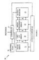
- Fig.2 is a block diagram of an embodiment of imaging system.
-
- The described embodiment provides a print head with a built-in imaging system that allows the position and shape of the drops produced by the nozzles be measured. In the preferred embodiment of the present invention, the position of each dot is measured relative to a reference dot during a calibration operation. The information is encoded for use by a printer driver to correct the trajectories of the dots. Since the print head already includes an integrated circuit chip, the present invention is preferably incorporated into that chip. Hence, the system does not markedly increase the cost of the print head or the printer.
- The manner in which the preferred system operates may be more easily understood with reference to Figure 1. which is a bottom view of a print head 10. Print head 10 includes two rows of nozzles shown at 12 and 13. An exemplary nozzle is shown at 14. Each row of nozzles is used for a different color ink. For simplicity only two of the rows normally found in a print head are shown; however it is to be understood that additional rows of nozzles are typically present. Color print heads typically have three or four rows of nozzles.
- An
imaging array 15 is located between two of the rows of nozzles. The array is preferably a two dimensional array having a pixel density that is greater than that of the nozzles so that the position and shape of the spots generated by the nozzles can be determined to a precision greater than the inter-nozzle spacing. In the preferred embodiment of the present invention, there are two imaging detectors for each nozzle. A typical photodetector is shown at 16. The print head moves bi-directionally in the direction shown at 18. - The output of each row of nozzles is measured separately. The direction of travel of the print head over the paper is selected such that
imaging array 15 passes over the spots generated by the current row of nozzles. In the preferred embodiment of the present invention,image array 15 is triggered by the detection of a spot generated bynozzle 19 bysensor 17. This assures that the image generated by the row of nozzles currently being measured in the center ofimaging array 15. - The system preferably utilizes an electronic shutter for the imaging operation. The preferred imaging array is a CMOS active pixel photo diode array. The detectors in the array integrate the light received by each detector since the array was last reset. Hence, the data must be read out of the array quickly if a separate shutter to control the light entering the array is not provided. In the preferred embodiment of the present invention the array consists of 600x64 photodetectors for measuring the output of 300 nozzles. The data in this array must be readout in 10 milli-seconds or less.
- The printer is typically connected to the computer by a relatively slow communication link; hence, the data from the imaging array cannot be read directly to the computer attached to the printer. Accordingly, the data must be processed on the chip and then sent to the computer for use by the calibration system. At a minimum, the data must be converted from analog to digital form and stored.
- In the preferred embodiment of the present invention, the data is also processed to further reduce the amount of data that must be sent to the computer. To provide the required processing speed, a separate one-bit A/D converter and a separate bit serial processor is provided for each of the 600 rows of image sensors in the array. Refer now to Figure 2, which is a block diagram of the preferred imaging system.
Imaging system 20 includes animaging array 21 such as described above with reference to Figure 1. Whenshutter pixel 26 detects the reference dot, the image array is reset. After the imaging array has received sufficiently exposure,controller 27 initiates the readout ofimaging array 21. The exposure time is short compared to the time needed for the print head to move the distance of one ink dot; hence, the imaging array "freezes" the motion. - The data from each row is shifted into a corresponding processor in
processor array 23 after being converted from analog to digital by the corresponding one-bit A/D converter in A/D converter array 22. The output of each bit serial processor inprocessor array 23 is stored in a corresponding 9-bit word inoutput register 24. The contents of this register are then read-out to the computer connected to the printer. The specific bit inimaging array 21 that is being processed at any given time is specified byaddress pointer 25 which connects that bit to the corresponding A/D converter and provides the address to the bit-serial processors. After all of the detectors inimage array 21 have been processed, the output ofregister 24 is sent to the processor under the control ofcontroller 27. The process is then repeated until all of the nozzles have been examined and the calibration procedure completed. Since the communication of data from a register to the processor is conventional in the art, it will not be discussed further here. - In the preferred embodiment of the present invention, the bit serial processors determine three parameters for each row of pixels. The first parameter is the location of the centroid of the ink drop, referred to as AddrC. Six of the 9 bits in the output register are utilized for this parameter. The second parameter is the size of the drop referred to as Wt. Two of the 9-bits in the output register are used for this parameter. The third parameter is an error flag, referred to as BigDot, which occupies one bit of the output registers. The error flag is set to indicate a dot that is bigger than 3 pixels wide. These parameters and the internal parameters, Space, Pass, and Mdot, are reset to zero at the beginning of the readout operation.
- On each clock cycle, the pixel at the current pointer location, AddrN, is converted by the one bit A/D converter to a binary value, DotN. This operation is triggered by the rising edge of a clock that is part of
controller 27. The falling edge of the clock signal triggers the bit serial process to perform the following algorithm:1. If DotN=0 and Wt=0 and Pass=0 No Action The line is blank up to this value of AddrN 2. If DotN=0 and Pass=1 No Action The line is blank after 1 or more dark pixels. 3. If DotN=0 and (Wt=1 or Wt=2 or Wt=3) and Space=1 and Pass=0 Pass=1 The calculation of the Centroid is complete. Note more than one space is used to indicate the end of an ink drop 4. If DotN=0 and (Wt=2 or Wt=3) and Space=0 and Pass=0 Space=1 Set the space variable to '1' as a first step in detecting the end of an ink drop. In this algorithm, a single space (DotN=0) between two dark dots (DotN=1) is allowed as part of a valid ink dot 5. If DotN=1 and Wt=3 and Pass=0 BigDot=1 If the size of the ink dot is greater than 3 pixels, then the ink dot is assumed to be too large. An output flag (BigDot=1) is used to indicate this condition. This variable may be used to adjust the reference level of the comparator in the 1-bit A/D converter for a second pass at reading the array. Pass=1 6. If DotN=1 and Wt=0 and Pass=0 Wt=1 This is the first pixel indicating the presence of an ink dot. Wt is set to '1' and the Centroid is the current AddrN AddrC=AddrN 7. If DotN=1 and Wt=1 and Space =0 and Pass=0 Wt=2 This is a second dark pixel adjacent to the first. Wt is incremented and the Centroid is changed to the current value of AddrN AddrC=AddrN 8. If Dot=1 and Wt=2 and Space=0 and Pass=0 Wt=3 This is a third dark pixel adjacent to the second. Wt is incremented and the Centroid does not change. 9. If DotN=0 and Wt=1 and Space=0 and Pass=0 Space=1 A space indicates either one valid space between dark pixels or the end of the ink dot. The value of the centroid does not change, the variable Space is set to '1', and a temporary variable (Mdot) is set to '1' Mdot=1 10. If DotN=1 and Space=1 and Wt=1 and Mdot=1 and Pass=0 AddrC=AddrN This is a dark pixel after a single space, the Centroid address is changed to AddrN, temporary variable Mdot is reset to '0', and dot weight variable is incremented. Mdot=0 Wt=2 11. If DotN=1 and Space=1 and Wt=2 and Mdot=1 and Pass=0 Wt=3 This is a dark pixel after a single space, the Centroid address is equal to AddrC defined in Step #7 above and the temporary variable Mdot is reset to '0' and the dot weight variable is incremented. 12. If DotN=1 and Space=1 and Wt=2 and Mdot=0 and Pass=0 Wt=3 This is a dark pixel following a dark pixel preceded by a space, the Centroid address is equal to AddrC defined in Step #10 above and the temporary variable Mdot is reset to '0' and the dot weight variable is incremented. Mdot=0 13. If Dotn=1 and Pass=1 BigDot=1 Error condition - 2 or more spaces between dark pixels. - While the preferred embodiment of the present invention provides the on-chip processing described above, it will be obvious to those skilled in the art from the preceding discussion that embodiments of the present invention that do not provide such processing may also be constructed. In one such embodiment,
processor array 23 shown in Figure 2 is eliminated and output register 24 is expanded to a width of 64 bits. - The described system assumes that sufficient ambient light is available to image the dots produced on the paper into the image sensor. Hence no light source is supplied on the chip. Since the described system is intended for use during calibration lights can be supplied at one location on the print carriage if the ambient light is not sufficient. However, it will be obvious to those skilled in the art from the preceding discussion that the sensor may include one or more LEDs for illuminating the area viewed by the imaging array. A light pipe may be used to channel light from discrete LEDs mounted near the print head to illuminate the imaging area under the print head. In this case, the LEDs can be pulsed to provide a light pulse which acts as an electronic shutter. If such a shutter arrangement is utilized the image can be stored on the imaging array for a period of time sufficient to readout the image array through the A/D converters directly to the processor. That is, output register 24 can also be eliminated.
- The above-described embodiments of the present invention utilized a
sensor 17 for triggering the imaging array. However, it will be obvious to those skilled in the art from the proceeding discussion that the array could also be triggered at a predetermined time after the nozzles are fired. The use ofsensor 17 is preferred, as the triggering is independent of the particular array of nozzles being calibrated. - The disclosure in United States patent application no. 09/072,408, from which this application claims priority, and in the abstract accompanying this application are incorporated herein by reference.
Claims (7)
- A print head comprising: a plurality of nozzles (12-14) for delivering droplets of ink onto a print medium thereby producing dots on said print medium; an imaging sensor (15-21) for forming an image of said dots, a controller (27) for reading out information derived from said image, characterised by a pixel sensor (17,26) comprising a photodetector for detecting a dot generated by a predetermined one (19) of said nozzles (12-14) and a circuit for generating a control signal in response to said photodetector detecting that dot for controlling said imaging sensor.
- A print head as in claim 1, wherein said nozzles (12-14) are arranged in a regular array and wherein said imaging sensor (15,21) comprises a regular two-dimensional array of photodetectors in which said photodetectors are spaced apart from one another by a distance less than the inter-nozzle spacing of said array.
- A print head as in claim 2, wherein said two-dimensional array of photodetectors comprises a plurality of rows of photodetectors; and wherein said print head (10,20) comprises a pointer (25) and a plurality of analog-to-digital converters (A/D) (22) each A/D corresponding to one of said rows, and being operable to generate a digital value indicative of a selected photodetector in said row corresponding to said A/D, said selected photodetector being specified by said pointer (25).
- A print head as in claim 3, comprising a plurality of processors (23) for processing the output of said A/Ds, one of said processors corresponding to each of said rows, each processor being operable to perform computations based on the A/D values generated for the row corresponding to that processor to generate an output corresponding to that row.
- A print head as in claim 4, wherein said output value indicates the location of the image of a portion of a dot that was imaged by said photodetectors in said row corresponding to said processor.
- A print head as in claim 4 or 5, wherein said output value indicates the size of the image of a portion of a dot that was imaged by said photodetectors in said row corresponding to said processor.
- A print head as in any one of claims 4 to 6, comprising an output register (24) including one word corresponding to each of said rows, said output register (24) being operable to store said output values generated by said processors (23).
Applications Claiming Priority (2)
| Application Number | Priority Date | Filing Date | Title |
|---|---|---|---|
| US09/072,408 US6227644B1 (en) | 1998-05-04 | 1998-05-04 | Inkjet dot imaging sensor for the calibration of inkjet print heads |
| US72408 | 1998-05-04 |
Publications (3)
| Publication Number | Publication Date |
|---|---|
| EP0955176A2 EP0955176A2 (en) | 1999-11-10 |
| EP0955176A3 EP0955176A3 (en) | 2000-06-28 |
| EP0955176B1 true EP0955176B1 (en) | 2005-08-17 |
Family
ID=22107356
Family Applications (1)
| Application Number | Title | Priority Date | Filing Date |
|---|---|---|---|
| EP99303246A Expired - Lifetime EP0955176B1 (en) | 1998-05-04 | 1999-04-27 | InkJet dot imaging sensor |
Country Status (4)
| Country | Link |
|---|---|
| US (1) | US6227644B1 (en) |
| EP (1) | EP0955176B1 (en) |
| JP (1) | JP4328410B2 (en) |
| DE (1) | DE69926682T2 (en) |
Families Citing this family (17)
| Publication number | Priority date | Publication date | Assignee | Title |
|---|---|---|---|---|
| US6211804B1 (en) * | 1998-05-04 | 2001-04-03 | Photobit Corporation | Using single lookup table to correct differential non-linearity errors in an array of A/D converters |
| US6419342B1 (en) * | 1999-11-19 | 2002-07-16 | Koninklijke Philips Electronics N.V. | Multi-function monitoring module for a printer |
| JP2001253062A (en) * | 2000-03-13 | 2001-09-18 | Canon Inc | Recording device and recording method |
| US6517180B2 (en) * | 2001-03-27 | 2003-02-11 | Hewlett-Packard Company | Dot sensing, color sensing and media sensing by a printer for quality control |
| DE10307136B4 (en) * | 2002-03-18 | 2008-08-21 | Heidelberger Druckmaschinen Ag | Method and apparatus for printing with error correction |
| WO2005096219A1 (en) | 2004-04-02 | 2005-10-13 | Silverbrook Research Pty Ltd | Surface having disposed therein or thereon coded data |
| US20050237348A1 (en) * | 2004-04-27 | 2005-10-27 | Campbell Michael C | Method of dot size determination by an imaging apparatus |
| US7264328B2 (en) * | 2004-09-30 | 2007-09-04 | Xerox Corporation | Systems and methods for print head defect detection and print head maintenance |
| US20060139670A1 (en) * | 2004-12-27 | 2006-06-29 | Hoblit Robert S | Method and system for correcting output of printer devices |
| JP5060315B2 (en) * | 2007-01-17 | 2012-10-31 | 京セラドキュメントソリューションズ株式会社 | Fixing device and image forming apparatus having the same |
| WO2008109529A2 (en) * | 2007-03-02 | 2008-09-12 | Marvell International Ltd. | Hand-propelled scrapbooking printer |
| KR20090020728A (en) * | 2007-08-24 | 2009-02-27 | 삼성전자주식회사 | Inkjet printheads and ink cartridges having the same |
| JP5545360B2 (en) * | 2010-04-02 | 2014-07-09 | 株式会社安川電機 | Signal processing apparatus, encoder and motor system |
| CN103862882B (en) * | 2014-02-24 | 2016-06-15 | 广东宝莱特医用科技股份有限公司 | A kind of method and system of thermal printer self adaptation Paper Printing |
| US9126446B1 (en) * | 2014-03-31 | 2015-09-08 | Xerox Corporation | System for detecting inoperative inkjets in printheads ejecting clear ink using a rotating member having a light transmitting surface |
| JP2021175600A (en) * | 2020-05-01 | 2021-11-04 | 株式会社リコー | Droplet ejection control device and droplet ejection device |
| WO2021232038A1 (en) * | 2020-05-13 | 2021-11-18 | Kateeva, Inc. | Droplet measurement using strobed led source |
Family Cites Families (12)
| Publication number | Priority date | Publication date | Assignee | Title |
|---|---|---|---|---|
| US4339208A (en) | 1980-09-25 | 1982-07-13 | Ncr Corporation | Optical sensing of wire matrix printers |
| US4493993A (en) * | 1982-11-22 | 1985-01-15 | Sperry Corporation | Apparatus for optically detecting ink droplets |
| JPS604372A (en) * | 1983-06-22 | 1985-01-10 | Canon Inc | Recording head controlling system |
| US4540990A (en) * | 1984-10-22 | 1985-09-10 | Xerox Corporation | Ink jet printer with droplet throw distance correction |
| JPS63260448A (en) * | 1987-04-17 | 1988-10-27 | Seiko Epson Corp | How to detect jetting errors in inkjet printers |
| JP2728436B2 (en) * | 1988-06-23 | 1998-03-18 | キヤノン株式会社 | Ink jet recording device |
| US4907013A (en) * | 1989-01-19 | 1990-03-06 | Pitney Bowes Inc | Circuitry for detecting malfunction of ink jet printhead |
| JPH03146383A (en) * | 1989-11-02 | 1991-06-21 | Canon Inc | recording device |
| EP0461759B1 (en) | 1990-05-11 | 1995-09-13 | Canon Kabushiki Kaisha | Recording apparatus for performing recording using recording head |
| JP3146383B2 (en) | 1991-07-05 | 2001-03-12 | コニカ株式会社 | Stabilizing solution for silver halide color photographic light-sensitive material, concentrated composition thereof, and processing method using the stabilizing solution |
| US5289208A (en) | 1991-10-31 | 1994-02-22 | Hewlett-Packard Company | Automatic print cartridge alignment sensor system |
| JP4405898B2 (en) | 2003-12-26 | 2010-01-27 | キヤノン株式会社 | Post-processing apparatus and image forming system |
-
1998
- 1998-05-04 US US09/072,408 patent/US6227644B1/en not_active Expired - Lifetime
-
1999
- 1999-04-27 EP EP99303246A patent/EP0955176B1/en not_active Expired - Lifetime
- 1999-04-27 DE DE69926682T patent/DE69926682T2/en not_active Expired - Lifetime
- 1999-04-30 JP JP12450599A patent/JP4328410B2/en not_active Expired - Fee Related
Also Published As
| Publication number | Publication date |
|---|---|
| JP4328410B2 (en) | 2009-09-09 |
| DE69926682T2 (en) | 2006-08-03 |
| EP0955176A2 (en) | 1999-11-10 |
| JPH11334058A (en) | 1999-12-07 |
| DE69926682D1 (en) | 2005-09-22 |
| EP0955176A3 (en) | 2000-06-28 |
| US6227644B1 (en) | 2001-05-08 |
Similar Documents
| Publication | Publication Date | Title |
|---|---|---|
| US6227644B1 (en) | Inkjet dot imaging sensor for the calibration of inkjet print heads | |
| EP0863004B1 (en) | Dynamic multi-pass print mode corrections to compensate for malfunctioning inkjet nozzles | |
| US6863361B2 (en) | Method to correct for malfunctioning ink ejection elements in a single pass print mode | |
| US6390588B1 (en) | Printing apparatus and method of detecting registration deviation | |
| JP5165127B2 (en) | Inkjet recording apparatus and inkjet recording control method | |
| JP2003145731A (en) | System and method for generating print mask for eliminating banding due to sheet step feed error and scanning width error | |
| EP1022149B1 (en) | Method and apparatus for establishing ink-jet printhead operating energy from an optical determination of turn-on energy | |
| US7249817B2 (en) | Printer having image dividing modes | |
| US7959253B2 (en) | Printing method, test pattern, method of producing test pattern, and printing apparatus | |
| US6390585B1 (en) | Selectively warming a printhead for optimized performance | |
| US7097266B2 (en) | Image printing apparatus and control method therefor | |
| JP4862547B2 (en) | Nozzle inspection apparatus, inkjet printer, nozzle inspection method, and nozzle inspection program | |
| US7467843B2 (en) | Methods for determining unidirectional print direction for improved print quality | |
| JP3120618B2 (en) | Thermal inkjet recording device | |
| JP3226642B2 (en) | Ink jet recording apparatus and method of adjusting density in ink jet recording apparatus | |
| JP2004188763A (en) | Inkjet recording device | |
| US20060192807A1 (en) | Printing Apparatus and Method of Controlling Printing Therein | |
| JP4541470B2 (en) | Recording method and recording apparatus | |
| JP4965911B2 (en) | Inkjet recording apparatus and inkjet recording control method | |
| JP2005007865A (en) | Printing apparatus, test pattern, and test pattern manufacturing method | |
| JP2001158089A (en) | Recording apparatus and recording method | |
| JP2002127379A (en) | Recording device | |
| JP2004237604A (en) | Density correction method | |
| JP2002127378A (en) | Recording device | |
| JP2002331652A (en) | Ink jet recording device |
Legal Events
| Date | Code | Title | Description |
|---|---|---|---|
| PUAI | Public reference made under article 153(3) epc to a published international application that has entered the european phase |
Free format text: ORIGINAL CODE: 0009012 |
|
| AK | Designated contracting states |
Kind code of ref document: A2 Designated state(s): DE FR GB |
|
| AX | Request for extension of the european patent |
Free format text: AL;LT;LV;MK;RO;SI |
|
| PUAL | Search report despatched |
Free format text: ORIGINAL CODE: 0009013 |
|
| AK | Designated contracting states |
Kind code of ref document: A3 Designated state(s): AT BE CH CY DE DK ES FI FR GB GR IE IT LI LU MC NL PT SE |
|
| AX | Request for extension of the european patent |
Free format text: AL;LT;LV;MK;RO;SI |
|
| 17P | Request for examination filed |
Effective date: 20000814 |
|
| AKX | Designation fees paid |
Free format text: DE FR GB |
|
| RAP1 | Party data changed (applicant data changed or rights of an application transferred) |
Owner name: HEWLETT-PACKARD COMPANY, A DELAWARE CORPORATION |
|
| 17Q | First examination report despatched |
Effective date: 20040116 |
|
| GRAP | Despatch of communication of intention to grant a patent |
Free format text: ORIGINAL CODE: EPIDOSNIGR1 |
|
| GRAS | Grant fee paid |
Free format text: ORIGINAL CODE: EPIDOSNIGR3 |
|
| GRAA | (expected) grant |
Free format text: ORIGINAL CODE: 0009210 |
|
| AK | Designated contracting states |
Kind code of ref document: B1 Designated state(s): DE FR GB |
|
| REG | Reference to a national code |
Ref country code: GB Ref legal event code: FG4D |
|
| REF | Corresponds to: |
Ref document number: 69926682 Country of ref document: DE Date of ref document: 20050922 Kind code of ref document: P |
|
| ET | Fr: translation filed | ||
| PLBE | No opposition filed within time limit |
Free format text: ORIGINAL CODE: 0009261 |
|
| STAA | Information on the status of an ep patent application or granted ep patent |
Free format text: STATUS: NO OPPOSITION FILED WITHIN TIME LIMIT |
|
| 26N | No opposition filed |
Effective date: 20060518 |
|
| PGFP | Annual fee paid to national office [announced via postgrant information from national office to epo] |
Ref country code: FR Payment date: 20070417 Year of fee payment: 9 |
|
| REG | Reference to a national code |
Ref country code: FR Ref legal event code: ST Effective date: 20081231 |
|
| PG25 | Lapsed in a contracting state [announced via postgrant information from national office to epo] |
Ref country code: FR Free format text: LAPSE BECAUSE OF NON-PAYMENT OF DUE FEES Effective date: 20080430 |
|
| REG | Reference to a national code |
Ref country code: GB Ref legal event code: 732E Free format text: REGISTERED BETWEEN 20120329 AND 20120404 |
|
| PGFP | Annual fee paid to national office [announced via postgrant information from national office to epo] |
Ref country code: GB Payment date: 20130326 Year of fee payment: 15 |
|
| PGFP | Annual fee paid to national office [announced via postgrant information from national office to epo] |
Ref country code: DE Payment date: 20130322 Year of fee payment: 15 |
|
| REG | Reference to a national code |
Ref country code: DE Ref legal event code: R119 Ref document number: 69926682 Country of ref document: DE |
|
| GBPC | Gb: european patent ceased through non-payment of renewal fee |
Effective date: 20140427 |
|
| REG | Reference to a national code |
Ref country code: DE Ref legal event code: R119 Ref document number: 69926682 Country of ref document: DE Effective date: 20141101 |
|
| PG25 | Lapsed in a contracting state [announced via postgrant information from national office to epo] |
Ref country code: GB Free format text: LAPSE BECAUSE OF NON-PAYMENT OF DUE FEES Effective date: 20140427 Ref country code: DE Free format text: LAPSE BECAUSE OF NON-PAYMENT OF DUE FEES Effective date: 20141101 |