EP0955119B1 - Disk housing for electric cutter with water-cooled cutting disk - Google Patents
Disk housing for electric cutter with water-cooled cutting disk Download PDFInfo
- Publication number
- EP0955119B1 EP0955119B1 EP99107406A EP99107406A EP0955119B1 EP 0955119 B1 EP0955119 B1 EP 0955119B1 EP 99107406 A EP99107406 A EP 99107406A EP 99107406 A EP99107406 A EP 99107406A EP 0955119 B1 EP0955119 B1 EP 0955119B1
- Authority
- EP
- European Patent Office
- Prior art keywords
- disk
- nozzle
- disk housing
- housing according
- blade
- Prior art date
- Legal status (The legal status is an assumption and is not a legal conclusion. Google has not performed a legal analysis and makes no representation as to the accuracy of the status listed.)
- Expired - Lifetime
Links
Images



Classifications
-
- B—PERFORMING OPERATIONS; TRANSPORTING
- B23—MACHINE TOOLS; METAL-WORKING NOT OTHERWISE PROVIDED FOR
- B23D—PLANING; SLOTTING; SHEARING; BROACHING; SAWING; FILING; SCRAPING; LIKE OPERATIONS FOR WORKING METAL BY REMOVING MATERIAL, NOT OTHERWISE PROVIDED FOR
- B23D59/00—Accessories specially designed for sawing machines or sawing devices
- B23D59/02—Devices for lubricating or cooling circular saw blades
-
- B—PERFORMING OPERATIONS; TRANSPORTING
- B28—WORKING CEMENT, CLAY, OR STONE
- B28D—WORKING STONE OR STONE-LIKE MATERIALS
- B28D1/00—Working stone or stone-like materials, e.g. brick, concrete or glass, not provided for elsewhere; Machines, devices, tools therefor
- B28D1/02—Working stone or stone-like materials, e.g. brick, concrete or glass, not provided for elsewhere; Machines, devices, tools therefor by sawing
- B28D1/04—Working stone or stone-like materials, e.g. brick, concrete or glass, not provided for elsewhere; Machines, devices, tools therefor by sawing with circular or cylindrical saw-blades or saw-discs
Definitions
- the present invention relates to a disk housing for an electric cutter with water-cooled disk.
- Cutting tables for tiles or the like above which a longitudinal horizontal guide is mounted are known as electric cutters; a carriage is mounted so that it can slide along the guide, and a motor assembly, which supports a cutting disk, is associated with said carriage so as to oscillate on a horizontal transverse axis.
- US-A-4 414 783 discloses a coolant system for use with a cutter of the type having a vertically disposed rotatable cutter wheel for cutting metallurgical samples and other objects.
- a cutter has a motor-driven rotatable abrasive or metal cutting wheel or blade, and a workpiece holder which holds a specimen workpiece from which a section is to be sliced off. Either the cutter wheel or the workpiece holder is movable to bring the workpiece into engagement with the cutter wheel.
- the coolant system is combined with a blade guard which covers a major portion of the rotatable cutting blade for safety reasons, and the coolant system distributes a coolant fluid onto the centre of the vertically disposed rotating cutting blade on both sides thereof so as to bathe the workpiece over the entire cutting area.
- the aim of the present invention is to obviate the above-mentioned drawbacks of conventional devices, by providing a disk housing for an electric cutter with a water-cooled disk cooling which is easy to assemble and not noisy in use, reduces outward water spray, and with which the disk blade is perfectly wet with water: the disk housing according to the invention is further capable of effectively protecting from the blade also when the motor assembly is rotated about a transverse axis.
- an object of the present invention is to provide a structure which is simple, relatively easy to provide in practice, safe in use, effective in operation and relatively of low cost.
- the present disk housing for an electric cutter with water-cooled disk characterized in that it comprises a pair of symmetrical semicircular plates which are peripherally provided with holes for screws for fixing onto the two faces of a perimetric support which is provided with interlock coupling means for a water supply duct and for a nozzle for spraying water onto the disk.
- the reference numeral 1 generally designates a disk housing for an electric cutter with water-cooled disk blade according to the invention.
- the disk housing 1 comprises two symmetrical semicircular plates 2, 3 which are peripherally provided with holes in mutually different positions; the first semicircular plate has three holes 4, while the second semicircular plate has two holes 5; said holes are meant for screws for fixing to the two faces of a perimetric support 6, and the semicircular plates are arranged parallel to each other and form, together with the support, a sort of flat box.
- the semicircular plates 2, 3 are substantially shaped like half of a regular polygon and have, at the diagonal from which the cutting disk blade D protrudes, respective edges 7 and 8 which are folded inward: the perimetric support 6, which is advantageously formed by molding materials such as the plastics known by the trade-name Nylon, has, on its two faces, respective external ridges 9 and 10 for the interlock coupling of the polygonal edges of the semicircular plates 2, 3.
- the perimetric support 6 is provided with interlock coupling means for a water supply duct 11 and for a nozzle 12 for spraying water onto the disk blade.
- the nozzle 12 is substantially fork-shaped in order to wrap around the disk and has water passage openings which are directed toward the inside of its prongs.
- the nozzle 12 is produced by molding materials such as the plastics known by the trade-name Nylon and is constituted by two symmetrical half-shells 13 and 14 which are fork-shaped and can be coupled together by interlocking through the insertion of corresponding pins 15 in corresponding holes 16; passage ducts 17 and water spray openings 18 are formed in the mutually contacting surfaces of the half-shells 13 and 14.
- the means for coupling the nozzle to the support are of the type with a tenon 19 for the base of the nozzle, which is crossed by a central hole 20 for the passage of water, and with a mortise 21 formed in the support.
- a tenon 19 for the base of the nozzle which is crossed by a central hole 20 for the passage of water, and with a mortise 21 formed in the support.
- two mutually opposite pins 22 which protrude from the nozzle, one half of said pins being formed in the half-shell 13 and the other half being formed in the half-shell 14, said pins fitting in corresponding holes 23 of the semicircular plates.
- the nozzle wraps around the cutting edge of the disk blade and that water is sprayed from all sides by means of three spraying points directly toward said disk blade; it is also noted that the nozzle can be easily disassembled and can then be opened, since it is formed by two half-shells, in order to rapidly clean the water passage ducts and openings.
- the semicircular plate 2 is provided with means 24 for hermetic rotary coupling to the head 25 of the motor M that drives the disk blade;
- the coupling means 24 comprise a flared spacer 26 which is centrally crossed by a hole 27 for the passage of the driving shaft.
- the spacer 26 has, on one face, an annular indent 28 which snugly and rotatably fits in an opening 29 of the semicircular plate 2.
- the reference numeral 30 designates an annular washer which is crossed by four holes 31 which are distributed in an annular pattern and in which corresponding screws 32 can be inserted. Such screws 32 pass through corresponding holes 33 of the spacer 26 and screw into respective threaded holes of the head 25 of the motor; the coupling means 24 allow the disk blade housing assembly to oscillate about the axis A of the shaft of the motor of the tile cutter.
- An articulation pivot 34 for the end 35 of a metal arm 36 is screwed into a hole 34a of the semicircular plate 2; the other end 37 of the metal arm is meant to be articulated, by means of a pivot 37a, to the elements that support the disk blade driving motor, and such arm is meant to cause a coupling of the articulated-parallelogram type in order to turn the disk blade housing when the disk blade driving motor is made to oscillate in a known manner about an axis B in order to keep the disk blade covered in a safe configuration.
- the support has, at the mortise for coupling the nozzle to the support and toward the outside, a through hole 38 for the hermetic coupling of a 90° coupling 39 for connection to the duct 11.
- the duct 11 is controlled by a cock 40, which is advantageously fitted to the disk housing 2 by means of a U-shaped element 41 which has a small hole 42a for fixing to one of the screws of the holes 4 and a wide opening 42b for the passage of the wings of the cock 40.
- the thicker region continues with a portion 47 crossed by a hole 48 which is arranged radially with respect to the half-disk and is meant to accommodate a screw 49 for fixing, by means of a reinforcement plate 50 and a nut 51, a spray guard flap 52 made of a spongy material suitable to absorb sprays.
- the portion 47 has a notch 53 for the rotation-preventing coupling of the hexagonal head of the screw 49 or rather of the corresponding nut 51.
- arrow 54 which is formed in relief and indelibly indicates the direction of rotation of the cutting disk blade.
Landscapes
- Engineering & Computer Science (AREA)
- Mechanical Engineering (AREA)
- Mining & Mineral Resources (AREA)
- Processing Of Stones Or Stones Resemblance Materials (AREA)
- Perforating, Stamping-Out Or Severing By Means Other Than Cutting (AREA)
- Finish Polishing, Edge Sharpening, And Grinding By Specific Grinding Devices (AREA)
- Sawing (AREA)
- Grinding-Machine Dressing And Accessory Apparatuses (AREA)
- Harvester Elements (AREA)
- Motor Or Generator Cooling System (AREA)
- Road Repair (AREA)
- Fluid-Pressure Circuits (AREA)
- Mirrors, Picture Frames, Photograph Stands, And Related Fastening Devices (AREA)
Abstract
Description
- The present invention relates to a disk housing for an electric cutter with water-cooled disk.
- Cutting tables for tiles or the like above which a longitudinal horizontal guide is mounted are known as electric cutters; a carriage is mounted so that it can slide along the guide, and a motor assembly, which supports a cutting disk, is associated with said carriage so as to oscillate on a horizontal transverse axis.
- Work with certain materials entails the use of disks whose cutting edge must be kept constantly clean and cool by means of a jet of water; accordingly, and also in order to reduce the danger of workplace accidents, the disk is protected by a housing which is usually rigidly fixed to the casing of the motor assembly.
- Conventional disk housings for electric cutters with water-cooled disk blade entail some drawbacks due to the fact that since they are usually made of a plurality of metal parts mutually joined by means of screws and bolts, they entail a rather troublesome assembly and can be noisy in use; additionally, a wide gap usually remains between the edge of the disk housing and the disk, allowing water spray to pass; further, the outlets for the water are usually provided crudely and accordingly the cutting region and the disk blade are poorly wet and cannot operate in an optimum manner.
- Another drawback is due to the fact that the disk housing is rigidly coupled to the frame of the motor and therefore when the motor is made to oscillate about a transverse axis which is parallel to the rotation axis in order to work in a different planned configuration, a rather wide angle of the blade is not protected by the disk housing.
- US-A-4 414 783 discloses a coolant system for use with a cutter of the type having a vertically disposed rotatable cutter wheel for cutting metallurgical samples and other objects. Such a cutter has a motor-driven rotatable abrasive or metal cutting wheel or blade, and a workpiece holder which holds a specimen workpiece from which a section is to be sliced off. Either the cutter wheel or the workpiece holder is movable to bring the workpiece into engagement with the cutter wheel. The coolant system is combined with a blade guard which covers a major portion of the rotatable cutting blade for safety reasons, and the coolant system distributes a coolant fluid onto the centre of the vertically disposed rotating cutting blade on both sides thereof so as to bathe the workpiece over the entire cutting area.
The aim of the present invention is to obviate the above-mentioned drawbacks of conventional devices, by providing a disk housing for an electric cutter with a water-cooled disk cooling which is easy to assemble and not noisy in use, reduces outward water spray, and with which the disk blade is perfectly wet with water: the disk housing according to the invention is further capable of effectively protecting from the blade also when the motor assembly is rotated about a transverse axis. - Within the scope of this aim, an object of the present invention is to provide a structure which is simple, relatively easy to provide in practice, safe in use, effective in operation and relatively of low cost.
- This aim, this object and others which will become apparent hereinafter are achieved by the present disk housing for an electric cutter with water-cooled disk, characterized in that it comprises a pair of symmetrical semicircular plates which are peripherally provided with holes for screws for fixing onto the two faces of a perimetric support which is provided with interlock coupling means for a water supply duct and for a nozzle for spraying water onto the disk.
- Further characteristics and advantages of the present invention will become apparent from the following detailed description of a preferred but not exclusive embodiment of a disk housing for an electric cutter with water-cooled disk according to the invention, illustrated only by way of non-limitative example in the accompanying drawings, wherein:
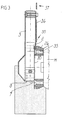
- Figure 1 is an exploded perspective view of a disk housing for an electric cutter with water-cooled disk according to the invention;
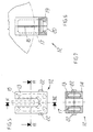
- Figure 2 is an enlarged-scale exploded perspective view of the water spray nozzle of the disk housing;
- Figure 3 is a partially sectional front view of a disk housing according to the invention;
- Figure 4 is a side view of a disk housing according to the invention, with one of the semicircular plates removed;
- Figure 5 is a top view of the nozzle of Figure 2;
- Figure 6 is a sectional side view of the nozzle, taken along the plane VI-VI of Figure 5;
- Figure 7 is a sectional front view of the nozzle, taken along the plane VII-VII of Figure 5.
-
- With particular reference to the above figures, the reference numeral 1 generally designates a disk housing for an electric cutter with water-cooled disk blade according to the invention.
- The disk housing 1 comprises two symmetrical
semicircular plates 2, 3 which are peripherally provided with holes in mutually different positions; the first semicircular plate has threeholes 4, while the second semicircular plate has twoholes 5; said holes are meant for screws for fixing to the two faces of aperimetric support 6, and the semicircular plates are arranged parallel to each other and form, together with the support, a sort of flat box. - The
semicircular plates 2, 3 are substantially shaped like half of a regular polygon and have, at the diagonal from which the cutting disk blade D protrudes,respective edges perimetric support 6, which is advantageously formed by molding materials such as the plastics known by the trade-name Nylon, has, on its two faces, respective external ridges 9 and 10 for the interlock coupling of the polygonal edges of thesemicircular plates 2, 3. - The
perimetric support 6 is provided with interlock coupling means for awater supply duct 11 and for anozzle 12 for spraying water onto the disk blade. - The
nozzle 12 is substantially fork-shaped in order to wrap around the disk and has water passage openings which are directed toward the inside of its prongs. Thenozzle 12 is produced by molding materials such as the plastics known by the trade-name Nylon and is constituted by two symmetrical half-shells corresponding pins 15 incorresponding holes 16;passage ducts 17 andwater spray openings 18 are formed in the mutually contacting surfaces of the half-shells - The means for coupling the nozzle to the support are of the type with a
tenon 19 for the base of the nozzle, which is crossed by acentral hole 20 for the passage of water, and with amortise 21 formed in the support. In order to lock the nozzle there are provided two mutuallyopposite pins 22 which protrude from the nozzle, one half of said pins being formed in the half-shell 13 and the other half being formed in the half-shell 14, said pins fitting incorresponding holes 23 of the semicircular plates. It is noted that the nozzle wraps around the cutting edge of the disk blade and that water is sprayed from all sides by means of three spraying points directly toward said disk blade; it is also noted that the nozzle can be easily disassembled and can then be opened, since it is formed by two half-shells, in order to rapidly clean the water passage ducts and openings. - The semicircular plate 2 is provided with
means 24 for hermetic rotary coupling to thehead 25 of the motor M that drives the disk blade; the coupling means 24 comprise a flaredspacer 26 which is centrally crossed by ahole 27 for the passage of the driving shaft. Thespacer 26 has, on one face, anannular indent 28 which snugly and rotatably fits in an opening 29 of the semicircular plate 2. Thereference numeral 30 designates an annular washer which is crossed by fourholes 31 which are distributed in an annular pattern and in whichcorresponding screws 32 can be inserted.Such screws 32 pass throughcorresponding holes 33 of thespacer 26 and screw into respective threaded holes of thehead 25 of the motor; the coupling means 24 allow the disk blade housing assembly to oscillate about the axis A of the shaft of the motor of the tile cutter. - An
articulation pivot 34 for theend 35 of ametal arm 36 is screwed into ahole 34a of the semicircular plate 2; theother end 37 of the metal arm is meant to be articulated, by means of apivot 37a, to the elements that support the disk blade driving motor, and such arm is meant to cause a coupling of the articulated-parallelogram type in order to turn the disk blade housing when the disk blade driving motor is made to oscillate in a known manner about an axis B in order to keep the disk blade covered in a safe configuration. - The support has, at the mortise for coupling the nozzle to the support and toward the outside, a
through hole 38 for the hermetic coupling of a 90°coupling 39 for connection to theduct 11. Theduct 11 is controlled by acock 40, which is advantageously fitted to the disk housing 2 by means of aU-shaped element 41 which has a small hole 42a for fixing to one of the screws of theholes 4 and a wide opening 42b for the passage of the wings of thecock 40. - In the
support 6, at the regions affected by theholes thicker regions 43 which are crossed byholes 44 for thescrews 45 for fixing the semicircular plates; the preferably hexagonal heads of thescrews 45 are recessed in corresponding hexagonal seats formed at one of the two ends of theholes 44, while alock nut 46, preferably of the self-locking type, is screwed at the free ends of the screws, after positioning the respective semicircular plate. - On the opposite side of the support with respect to the one where the nozzle is fixed, the thicker region continues with a
portion 47 crossed by ahole 48 which is arranged radially with respect to the half-disk and is meant to accommodate ascrew 49 for fixing, by means of areinforcement plate 50 and anut 51, aspray guard flap 52 made of a spongy material suitable to absorb sprays. Advantageously, theportion 47 has anotch 53 for the rotation-preventing coupling of the hexagonal head of thescrew 49 or rather of thecorresponding nut 51. - Conveniently, on the exposed surface of the
support 6 there is anarrow 54 which is formed in relief and indelibly indicates the direction of rotation of the cutting disk blade. - It has thus been shown that the invention achieves the intended aim and objects.
- The invention thus conceived is susceptible of numerous modifications and variations within the scope of the invention defined by the claims.
- In practice, the materials used, as well as the shapes and the dimensions, may be any according to requirements without thereby abandoning the scope of the protection of the appended claims.
- Where technical features mentioned in any claim are followed by reference signs, those reference signs have been included for the sole purpose of increasing the intelligibility of the claims and accordingly, such reference signs do not have any limiting effect on the interpretation of each element identified by way of example by such reference signs.
Claims (10)
- A disk housing for an electric cutter with a water-cooled disk blade (D), comprising a water supply duct, a nozzle (12) for spraying water onto said disk blade (D), a perimetric support (6) which is provided with interlock coupling means for coupling said nozzle (12) to said perimetric support (6), characterised in that it further comprises a pair of plates (2, 3) which are peripherally provided with holes (4, 5) for screws for fixing said plates (2, 3) onto the two faces of said perimetric support (6) and in that said interlock coupling means comprises a receptacle (21) formed in said perimetric support (6) and so configured as to receive a base portion (19) of said nozzle (12).
- A disk housing according to claim 1, wherein said interlock coupling means further comprises pins (22) protruding from said nozzle (12) and fitting in corresponding holes (23) obtained in said plates (2, 3).
- A disk housing according to claim 1, or 2, wherein said plates (2, 3) are substantially shaped like half of a regular polygon and in that at the diagonal from which said disk blade (D) protrudes they have respective borders (7, 8) which fold inward.
- A disk housing according any preceding claims, wherein said perimetric support (6) has, on its two faces, respective external ridges (9, 10) for the interlock coupling of perimetric edges of said plates.
- A disk housing according to any preceding claims, wherein said nozzle (12) is substantially fork-shaped, in order to wrap around said disk blade (D), and has openings (18) for the passage of water which are directed toward the inside of prongs of said nozzle (12).
- A disk housing according to any preceding claims, wherein one of said plates has means (24) for rotary hermetic coupling to the head of a motor (M) that drives said disk blade (D).
- A disk housing according to any preceding claims, wherein one of said plates has an articulation pivot (34) for an end (35) of an arm (36) whose other end (37) is articulated to elements that support a motor (M) that drives said disk blade (D), said arm (36) being adapted to turn said disk housing (1) when said motor (M) is made to oscillate, in order to keep said disk blade (D) in a protective configuration.
- The disk housing according to any preceding claims, wherein said nozzle (12) is constituted by two symmetrical fork-shaped half-shells (13, 14) which are mutually coupled by interlocking, passage ducts (17) and water spray openings (18) being formed in contacting surfaces thereof.
- A disk housing according any preceding claims, wherein on the part of said perimetric support (6) that lies opposite to the part where said nozzle (16) is fixed there is a thicker portion (47) which is crossed by a hole (48) for a screw (49) for fixing a spray guard flap made of spongy material.
- A disk housing according to any preceding claims, wherein on the exposed surface of said perimetric support (6) there is an arrow (54) in relief which is suitable to indicate the direction of rotation of said disk blade (D).
Priority Applications (1)
| Application Number | Priority Date | Filing Date | Title |
|---|---|---|---|
| EP04021782A EP1547713B1 (en) | 1998-05-07 | 1999-04-26 | An electric cutter with water-cooled disk |
Applications Claiming Priority (2)
| Application Number | Priority Date | Filing Date | Title |
|---|---|---|---|
| IT98BO000291A IT1300015B1 (en) | 1998-05-07 | 1998-05-07 | DISC COVER FOR ELECTRIC CUTTER WITH WATER DISC COOLING. |
| ITBO980291 | 1998-05-07 |
Related Child Applications (1)
| Application Number | Title | Priority Date | Filing Date |
|---|---|---|---|
| EP04021782A Division EP1547713B1 (en) | 1998-05-07 | 1999-04-26 | An electric cutter with water-cooled disk |
Publications (3)
| Publication Number | Publication Date |
|---|---|
| EP0955119A2 EP0955119A2 (en) | 1999-11-10 |
| EP0955119A3 EP0955119A3 (en) | 2001-10-10 |
| EP0955119B1 true EP0955119B1 (en) | 2004-12-22 |
Family
ID=11343163
Family Applications (2)
| Application Number | Title | Priority Date | Filing Date |
|---|---|---|---|
| EP99107406A Expired - Lifetime EP0955119B1 (en) | 1998-05-07 | 1999-04-26 | Disk housing for electric cutter with water-cooled cutting disk |
| EP04021782A Expired - Lifetime EP1547713B1 (en) | 1998-05-07 | 1999-04-26 | An electric cutter with water-cooled disk |
Family Applications After (1)
| Application Number | Title | Priority Date | Filing Date |
|---|---|---|---|
| EP04021782A Expired - Lifetime EP1547713B1 (en) | 1998-05-07 | 1999-04-26 | An electric cutter with water-cooled disk |
Country Status (5)
| Country | Link |
|---|---|
| EP (2) | EP0955119B1 (en) |
| AT (2) | ATE285310T1 (en) |
| DE (1) | DE69922734T2 (en) |
| ES (2) | ES2234181T3 (en) |
| IT (1) | IT1300015B1 (en) |
Families Citing this family (5)
| Publication number | Priority date | Publication date | Assignee | Title |
|---|---|---|---|---|
| US7281535B2 (en) * | 2004-02-23 | 2007-10-16 | Towa Intercon Technology, Inc. | Saw singulation |
| FR2868348B1 (en) * | 2004-04-05 | 2007-06-29 | Tecma Soc Par Actions Simplifi | SAWING MODULE |
| ES2324381B1 (en) * | 2007-04-20 | 2010-05-26 | Raquel Durban Asensio (1/3) | PROTECTIVE HOUSING OF THE CUTTING TOOL FOR CUTTING MACHINES FOR CONSTRUCTION. |
| EP2965886B1 (en) | 2014-06-18 | 2020-12-02 | Husqvarna AB | Tile or masonry saw assembly with improved blade wetting capability |
| CN107639702A (en) * | 2017-10-31 | 2018-01-30 | 天津三田协楔科技股份有限公司 | A kind of automatic worktable cutter device |
Family Cites Families (13)
| Publication number | Priority date | Publication date | Assignee | Title |
|---|---|---|---|---|
| GB826194A (en) * | 1956-05-28 | 1959-12-31 | Bull Sa Machines | Improvements relating to cooling systems for machine tools |
| US2876810A (en) * | 1958-03-04 | 1959-03-10 | Joseph M Peterson | Point of operation saw guard |
| FR1242791A (en) * | 1959-06-02 | 1960-09-30 | Felker Mfg Co | Saw |
| US2972344A (en) * | 1959-10-19 | 1961-02-21 | Felker Mfg Co | Adjustable mounting for rotary saw |
| FR1600356A (en) * | 1968-01-09 | 1970-07-20 | ||
| DE2060694C3 (en) * | 1970-12-10 | 1974-05-02 | Hutton Norman Horatio | Protective cover for a grinding wheel acting on the circumference |
| DE2904685A1 (en) * | 1979-02-08 | 1980-08-21 | Mey Kg Maschf Mafell | CIRCULAR SAW |
| US4414783A (en) * | 1981-08-19 | 1983-11-15 | Buehler Ltd. | Coolant system for rotating blade cutter |
| DE8137765U1 (en) * | 1981-12-24 | 1982-07-01 | Festo-Maschinenfabrik Gottlieb Stoll, 7300 Esslingen | HAND CIRCULAR SAW, IN PARTICULAR TO CUT ASBEST OR ACRYLIC GLASS OR PLEXIGLASS PANELS OR -PIECES, COATED MOLDING PIECES OR THE LIKE. |
| US4676557A (en) * | 1984-07-20 | 1987-06-30 | Cimline, Inc. | Cooling system for wheeled saw |
| US4619081A (en) * | 1985-02-28 | 1986-10-28 | General Signal Corporation | Combined nozzle with air foil |
| JP2517369Y2 (en) * | 1990-06-21 | 1996-11-20 | リョービ株式会社 | Tabletop cutting machine |
| DE29802546U1 (en) * | 1998-02-14 | 1998-04-23 | Lissmac Maschinenbau und Diamantwerkzeuge GmbH, 88410 Bad Wurzach | Sawing device |
-
1998
- 1998-05-07 IT IT98BO000291A patent/IT1300015B1/en active IP Right Grant
-
1999
- 1999-04-26 ES ES99107406T patent/ES2234181T3/en not_active Expired - Lifetime
- 1999-04-26 AT AT99107406T patent/ATE285310T1/en active
- 1999-04-26 EP EP99107406A patent/EP0955119B1/en not_active Expired - Lifetime
- 1999-04-26 DE DE69922734T patent/DE69922734T2/en not_active Expired - Lifetime
- 1999-04-26 EP EP04021782A patent/EP1547713B1/en not_active Expired - Lifetime
- 1999-04-26 ES ES04021782T patent/ES2380615T3/en not_active Expired - Lifetime
- 1999-04-26 AT AT04021782T patent/ATE540772T1/en active
Also Published As
| Publication number | Publication date |
|---|---|
| ES2234181T3 (en) | 2005-06-16 |
| DE69922734T2 (en) | 2005-12-08 |
| ITBO980291A0 (en) | 1998-05-07 |
| ES2380615T3 (en) | 2012-05-16 |
| ATE540772T1 (en) | 2012-01-15 |
| EP1547713B1 (en) | 2012-01-11 |
| EP1547713A2 (en) | 2005-06-29 |
| EP1547713A3 (en) | 2005-11-02 |
| EP0955119A3 (en) | 2001-10-10 |
| EP0955119A2 (en) | 1999-11-10 |
| ATE285310T1 (en) | 2005-01-15 |
| DE69922734D1 (en) | 2005-01-27 |
| IT1300015B1 (en) | 2000-04-04 |
| ITBO980291A1 (en) | 1999-11-07 |
Similar Documents
| Publication | Publication Date | Title |
|---|---|---|
| CA1286953C (en) | Compound miter saw | |
| US6241594B1 (en) | Hand machine tool adjustable front handle | |
| US7926398B2 (en) | Cutter with optical alignment system | |
| US6405624B2 (en) | Splitter and cutting member guard assembly | |
| CA1138305A (en) | Motorized miter saw fence mounting | |
| US4427042A (en) | Power tool | |
| EP0810071B1 (en) | Viewing window for circular saw guard | |
| US5953820A (en) | Chisels and scrapers with replaceable blades | |
| US6699114B1 (en) | Pivotal guards for power hand tools with rotating discs | |
| EP0653364B1 (en) | Improved shaft assembly | |
| CA1130173A (en) | Motorized circular miter chop saw | |
| CA1231236A (en) | Drill powered wet or dry abrasive apparatus | |
| US7980163B2 (en) | Air deflector assemblies for miter saws | |
| KR19990077458A (en) | The chamfering tool | |
| EP1547713B1 (en) | An electric cutter with water-cooled disk | |
| CA1122011A (en) | Dental model trimmer | |
| US4384502A (en) | Motorized circular miter chop saw | |
| US12122007B2 (en) | Blade guard for saw of saw house and method | |
| AU2024695A (en) | Rotary cutters | |
| EP1533064B1 (en) | An electric miter saw | |
| US5725419A (en) | Apparatus for removing excess material from workpieces | |
| JPH06270138A (en) | Cooler of circular saw | |
| US5022447A (en) | Safeguard apparatus for cutter of joint planer | |
| US4237853A (en) | Dresser design | |
| US20240227241A9 (en) | Concrete saw with cutting enclosure and dust collection system |
Legal Events
| Date | Code | Title | Description |
|---|---|---|---|
| PUAI | Public reference made under article 153(3) epc to a published international application that has entered the european phase |
Free format text: ORIGINAL CODE: 0009012 |
|
| AK | Designated contracting states |
Kind code of ref document: A2 Designated state(s): AT BE CH CY DE DK ES FI FR GB GR IE IT LI LU MC NL PT SE Kind code of ref document: A2 Designated state(s): AT DE ES FR GB IT |
|
| AX | Request for extension of the european patent |
Free format text: AL;LT;LV;MK;RO;SI |
|
| PUAL | Search report despatched |
Free format text: ORIGINAL CODE: 0009013 |
|
| AK | Designated contracting states |
Kind code of ref document: A3 Designated state(s): AT BE CH CY DE DK ES FI FR GB GR IE IT LI LU MC NL PT SE |
|
| AX | Request for extension of the european patent |
Free format text: AL;LT;LV;MK;RO;SI |
|
| 17P | Request for examination filed |
Effective date: 20020320 |
|
| AKX | Designation fees paid |
Free format text: AT DE ES FR GB IT |
|
| 17Q | First examination report despatched |
Effective date: 20031205 |
|
| GRAP | Despatch of communication of intention to grant a patent |
Free format text: ORIGINAL CODE: EPIDOSNIGR1 |
|
| GRAS | Grant fee paid |
Free format text: ORIGINAL CODE: EPIDOSNIGR3 |
|
| GRAA | (expected) grant |
Free format text: ORIGINAL CODE: 0009210 |
|
| AK | Designated contracting states |
Kind code of ref document: B1 Designated state(s): AT DE ES FR GB IT |
|
| REG | Reference to a national code |
Ref country code: GB Ref legal event code: FG4D |
|
| REF | Corresponds to: |
Ref document number: 69922734 Country of ref document: DE Date of ref document: 20050127 Kind code of ref document: P |
|
| REG | Reference to a national code |
Ref country code: ES Ref legal event code: FG2A Ref document number: 2234181 Country of ref document: ES Kind code of ref document: T3 |
|
| PLBE | No opposition filed within time limit |
Free format text: ORIGINAL CODE: 0009261 |
|
| STAA | Information on the status of an ep patent application or granted ep patent |
Free format text: STATUS: NO OPPOSITION FILED WITHIN TIME LIMIT |
|
| 26N | No opposition filed |
Effective date: 20050923 |
|
| ET | Fr: translation filed | ||
| PG25 | Lapsed in a contracting state [announced via postgrant information from national office to epo] |
Ref country code: IT Free format text: LAPSE BECAUSE OF NON-PAYMENT OF DUE FEES Effective date: 20080426 |
|
| PGRI | Patent reinstated in contracting state [announced from national office to epo] |
Ref country code: IT Effective date: 20110616 |
|
| PGFP | Annual fee paid to national office [announced via postgrant information from national office to epo] |
Ref country code: ES Payment date: 20120410 Year of fee payment: 14 |
|
| PGFP | Annual fee paid to national office [announced via postgrant information from national office to epo] |
Ref country code: AT Payment date: 20120323 Year of fee payment: 14 |
|
| PGFP | Annual fee paid to national office [announced via postgrant information from national office to epo] |
Ref country code: GB Payment date: 20130326 Year of fee payment: 15 |
|
| PGFP | Annual fee paid to national office [announced via postgrant information from national office to epo] |
Ref country code: DE Payment date: 20130322 Year of fee payment: 15 |
|
| PGFP | Annual fee paid to national office [announced via postgrant information from national office to epo] |
Ref country code: FR Payment date: 20130603 Year of fee payment: 15 Ref country code: IT Payment date: 20130423 Year of fee payment: 15 |
|
| REG | Reference to a national code |
Ref country code: DE Ref legal event code: R119 Ref document number: 69922734 Country of ref document: DE |
|
| REG | Reference to a national code |
Ref country code: AT Ref legal event code: MM01 Ref document number: 285310 Country of ref document: AT Kind code of ref document: T Effective date: 20140426 |
|
| GBPC | Gb: european patent ceased through non-payment of renewal fee |
Effective date: 20140426 |
|
| REG | Reference to a national code |
Ref country code: FR Ref legal event code: ST Effective date: 20141231 |
|
| REG | Reference to a national code |
Ref country code: DE Ref legal event code: R119 Ref document number: 69922734 Country of ref document: DE Effective date: 20141101 |
|
| PG25 | Lapsed in a contracting state [announced via postgrant information from national office to epo] |
Ref country code: DE Free format text: LAPSE BECAUSE OF NON-PAYMENT OF DUE FEES Effective date: 20141101 Ref country code: GB Free format text: LAPSE BECAUSE OF NON-PAYMENT OF DUE FEES Effective date: 20140426 |
|
| PG25 | Lapsed in a contracting state [announced via postgrant information from national office to epo] |
Ref country code: AT Free format text: LAPSE BECAUSE OF NON-PAYMENT OF DUE FEES Effective date: 20140426 Ref country code: FR Free format text: LAPSE BECAUSE OF NON-PAYMENT OF DUE FEES Effective date: 20140430 |
|
| PG25 | Lapsed in a contracting state [announced via postgrant information from national office to epo] |
Ref country code: IT Free format text: LAPSE BECAUSE OF NON-PAYMENT OF DUE FEES Effective date: 20140426 |
|
| PG25 | Lapsed in a contracting state [announced via postgrant information from national office to epo] |
Ref country code: ES Free format text: LAPSE BECAUSE OF NON-PAYMENT OF DUE FEES Effective date: 20140427 |