EP0954750B1 - Bauteil aus duktilem metallischem werkstoff und verfahren zur bestimmung von verformungen und/oder belastungen mittels schallemissionsanalyse - Google Patents
Bauteil aus duktilem metallischem werkstoff und verfahren zur bestimmung von verformungen und/oder belastungen mittels schallemissionsanalyse Download PDFInfo
- Publication number
- EP0954750B1 EP0954750B1 EP98907830A EP98907830A EP0954750B1 EP 0954750 B1 EP0954750 B1 EP 0954750B1 EP 98907830 A EP98907830 A EP 98907830A EP 98907830 A EP98907830 A EP 98907830A EP 0954750 B1 EP0954750 B1 EP 0954750B1
- Authority
- EP
- European Patent Office
- Prior art keywords
- particles
- component
- component according
- brittle
- sound emission
- Prior art date
- Legal status (The legal status is an assumption and is not a legal conclusion. Google has not performed a legal analysis and makes no representation as to the accuracy of the status listed.)
- Expired - Lifetime
Links
Images




Classifications
-
- C—CHEMISTRY; METALLURGY
- C22—METALLURGY; FERROUS OR NON-FERROUS ALLOYS; TREATMENT OF ALLOYS OR NON-FERROUS METALS
- C22C—ALLOYS
- C22C32/00—Non-ferrous alloys containing at least 5% by weight but less than 50% by weight of oxides, carbides, borides, nitrides, silicides or other metal compounds, e.g. oxynitrides, sulfides, whether added as such or formed in situ
- C22C32/0089—Non-ferrous alloys containing at least 5% by weight but less than 50% by weight of oxides, carbides, borides, nitrides, silicides or other metal compounds, e.g. oxynitrides, sulfides, whether added as such or formed in situ with other, not previously mentioned inorganic compounds as the main non-metallic constituent, e.g. sulfides, glass
-
- G—PHYSICS
- G01—MEASURING; TESTING
- G01N—INVESTIGATING OR ANALYSING MATERIALS BY DETERMINING THEIR CHEMICAL OR PHYSICAL PROPERTIES
- G01N29/00—Investigating or analysing materials by the use of ultrasonic, sonic or infrasonic waves; Visualisation of the interior of objects by transmitting ultrasonic or sonic waves through the object
- G01N29/14—Investigating or analysing materials by the use of ultrasonic, sonic or infrasonic waves; Visualisation of the interior of objects by transmitting ultrasonic or sonic waves through the object using acoustic emission techniques
-
- G—PHYSICS
- G01—MEASURING; TESTING
- G01N—INVESTIGATING OR ANALYSING MATERIALS BY DETERMINING THEIR CHEMICAL OR PHYSICAL PROPERTIES
- G01N29/00—Investigating or analysing materials by the use of ultrasonic, sonic or infrasonic waves; Visualisation of the interior of objects by transmitting ultrasonic or sonic waves through the object
- G01N29/22—Details, e.g. general constructional or apparatus details
- G01N29/227—Details, e.g. general constructional or apparatus details related to high pressure, tension or stress conditions
-
- B—PERFORMING OPERATIONS; TRANSPORTING
- B22—CASTING; POWDER METALLURGY
- B22F—WORKING METALLIC POWDER; MANUFACTURE OF ARTICLES FROM METALLIC POWDER; MAKING METALLIC POWDER; APPARATUS OR DEVICES SPECIALLY ADAPTED FOR METALLIC POWDER
- B22F2998/00—Supplementary information concerning processes or compositions relating to powder metallurgy
Definitions
- the invention relates to components made of ductile metallic Materials, their deformation or on them exposure to noise emission analysis should be determined.
- Another option is the components to use in the development phase and for example the deformation behavior at which actually occurring different possible loads determine and for the final construction too consider. With known deformation behavior it is of course also possible, also the to determine the respective applied load.
- highly stressed, cost-intensive components for example in the automotive industry, Aviation or heavy engineering possible as well as for components whose damage high risk potential.
- ductile metallic materials e.g. ductile Steels used. Because the ductile metallic Materials are only slightly noise-active, If at all, sound emission analysis can only are used conditionally because the signals that can be evaluated and in particular the measurable amplitudes in an area that is not accessible for evaluation is and at least the required measurement accuracy is not big enough.
- US Pat. No. 5,423,222 describes a method for Determination of deformations in sealing elements described. This teaching is followed that in such a sealing element or one Road surface a marking substance made up of individual Particles evenly distributed with a certain amount becomes. In the aftermath of a deformation the changed density and distribution of the particles of the Marking substance determined, being a suitable Energy radiation is used.
- property changes which is used for the measurement can be electrical, magnetic, acoustic or called optical property changes, being the change in acoustic impedance of the so prepared material has been mentioned and in the latter case ultrasound as a suitable energy radiation Should find use.
- the ductile metallic material that prefers a weldable structural steel but also a ductile one Light metal alloy (e.g. aluminum alloy) can, is used to increase the sound emission behavior added a substance in particulate form, which at least in Temperature range below 400 ° C is brittle. there the particles should at least be in the operating temperature range of the component in question, e.g. at Room temperature.
- a ductile one Light metal alloy e.g. aluminum alloy
- the particles are also in the forming temperature range are plastically deformable so that a certain structure (stretched or needle shape) the particles, for example during work hardening can be achieved.
- the particles can also start from the surface by rolling, pressing or plating in the metallic material are introduced.
- there can be a locally differentiated arrangement of the brittle Particles can be reached in the component, which is for certain Applications can be cheap. So can be critical Component areas become more noise-active than non-critical areas. The latter procedure lead to an accumulation of particles in the surface area the components and in particular voltages, that have the greatest impact in this area, can be better detected.
- the introduction of the Particles can be used with an otherwise necessary Process step for the production of the component can be introduced (shaping).
- the proportion of brittle particles in the metal can be relative be kept low and the small amount does not or only slightly leads to the fact that actually desired from the base material of the component Properties are adversely affected.
- the necessary Shares are below 20 vol .-%, it however, shares below 2 vol% and proportions below 1% by volume already cause one greatly improved acoustic emission activity that now also ductile materials for sound emission analysis makes accessible.
- the size of the particles should be in the range between 1 and 200 microns, preferably kept between 1 and 100 microns his.
- the respective melting point should be used for the selection be taken into account. At low melting point are correspondingly lower forming temperatures for the Possible material. However, it should also be noted that the operating temperature range for the components reduced accordingly.
- the stretched one already described as advantageous Shape of the particles that are acicular in the micrograph is recognizable, can be caused by plastic deformation mechanical or thermomechanical treatment achieved become.
- mechanical Properties e.g. strength and fracture toughness
- Base materials can be the sound emission activity through targeted selection of the number, type, size and possibly the arrangement of the brittle particles optimized become.
- a possible criterion for optimization can the noise emission behavior at the yield point of the ductile metallic material.
- the targeted Setting the sound emission activity can taking into account the increased noise emission the yield strength or just for the whole Deformation range can be optimized up to the fracture limit.
- the components of the invention are particularly for Suitable for certain areas of application, around certain loads already during construction, that affect the respective component to be able to. Weak points can be identified and be balanced constructively.
- a monitoring of the component during operation acting loads and the resulting Deformations can be carried out to be more specific when reaching or exceeding Limits to generate a signal and an exchange a critically damaged component initiate.
- the measurement is made more sensitive by coupling Piezo sensors on the component, whose measurement signals after sufficient reinforcement can be evaluated.
- a sensor can be used on the component, but advantageously also several sensors coupled locally separately his.
- a postponed or parallel evaluation The sound emission signals can be for each sensor selected.
- the use of Multiple sensors can be used when evaluating each Time delay of the measured signals the possibility open up a local assignment of the measurement signals on Allow component.
- Such components according to the invention can be advantageous be designed so that their contour is limited locally Weaknesses (e.g. notches, cross-sectional reductions) that provide a signal depending on the use, at which the break resistance or yield point of the component has not yet been reached or is in the construction phase corresponding influences in the design and material selection should be checked.
- Weaknesses e.g. notches, cross-sectional reductions
- the measurement accuracy of such a sound emission analysis can be further improved if only the number of burst signals above a predeterminable Limit value are determined and taken into account become.
- a limit can for measurements with sensitive piezoelectric Sensors, especially under actual operating conditions be increased with the invention so that sound emission analysis not only under laboratory conditions performed but with the higher Limit of the influence of the disturbance variable is reduced.
- the need to replace an inventive one The component can also be determined and displayed that the certain number of amplitudes with at least one material and / or component specific predeterminable maximum value is compared, so that if this maximum value is exceeded, a corresponding one Signal is generated.
- Figure 1 is a block diagram of a measurement setup to carry out a sound emission analysis shown.
- a sound emission receiver is placed on component 1 2 put on and acoustically coupled.
- the sound emission sensor 2 can be permanent but also releasably connected to component 1 his.
- a coupler 4 and a Bandpass filter 5 get the amplified and selected Sound emission signals in an evaluation unit 6 (e.g. personal computer).
- the evaluation takes place about calibration values or courses, which in one Are stored in the evaluation unit 6 and be compared with the measured values, e.g. the deformation or the yield point or exceeding it capture.
- Figure 2 the structure of a tensile test is on a tension rod as component 1 is shown schematically. In doing so, a defined tractive force or a corresponding one Predeterminable force curve applied and the Elongation (deformation) of the component in parallel with a conventional strain transducer 7 (e.g. using a strain gauge) and a sound emission sensor 2 measured.
- a conventional strain transducer 7 e.g. using a strain gauge
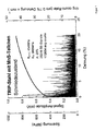
- FIG. 3 gives accordingly Figure 2 measured measured value curves on a conventional component made of a ductile steel 8.8 mass% Cr, 8.4 mass% Ni, 4.2 mass% Mo, 1.8 Mass% Mn, 1.7 mass% Si, 0.5 mass% C and 0.02 Mass% S again.
- the diagram contains the course of the measured Acoustic emission energy.
- the individual acoustic emission energy amplitudes show that these signals are an evaluation of the deformation (Stretching) or recognizing the exceeding of the Do not allow the yield strength of this material, because a relationship between these measurements and the Component stress not recognizable and verifiable is.
- an inventive Component is a steel with 8.8 mass% Cr, 8.4 mass% Ni, 4.2% by mass Mo, 1.8% by mass Mn, 1.7% by mass Si, 0.5 Mass% C, 0.02 mass% S and 0.5 mass% MnS particles 9 Powder metallurgically installed homogeneously.
- MnS particles 9 became plastic after hot deformation deformed, as can be seen in Figure 5.
- the size of the deformed particles 9 is this Example only in the area around 10 ⁇ m.
- the MnS particles 9 are at room temperature brittle and this leads surprisingly during deformation cause the yield strength to be exceeded and the additional plastic deformation also for materials that are actually used for sound emission analysis are not accessible, detectable are.
- FIG. 6 and 7 show further diagrams, where a sound emission analysis on components with other reference values is, the corresponding components from one Material with a composition that is Figure 3 for the diagram in Figure 6 and that of Figure 4 corresponds to the diagram in FIG. 7 become.
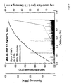
- Figures 7 and 8 show diagrams of components from AlLi 5, the diagram showing the corresponding Measured values of a sound emission analysis on a conventional and FIG. 8 with one according to the invention modified AlLi 5, the brittle particle made of SiC (17.5% by volume) have been added.
- Figure 9 is then a diagram of means voltages measured in a sound emission analysis a component according to the invention made of a 0.25% carbon steel with MnS particles (1% by volume).
Landscapes
- Chemical & Material Sciences (AREA)
- Physics & Mathematics (AREA)
- General Health & Medical Sciences (AREA)
- Pathology (AREA)
- Immunology (AREA)
- General Physics & Mathematics (AREA)
- Biochemistry (AREA)
- Analytical Chemistry (AREA)
- Health & Medical Sciences (AREA)
- Life Sciences & Earth Sciences (AREA)
- Engineering & Computer Science (AREA)
- Organic Chemistry (AREA)
- Inorganic Chemistry (AREA)
- Metallurgy (AREA)
- Mechanical Engineering (AREA)
- Materials Engineering (AREA)
- Acoustics & Sound (AREA)
- Investigating Strength Of Materials By Application Of Mechanical Stress (AREA)
- Investigating Or Analyzing Materials By The Use Of Ultrasonic Waves (AREA)
Abstract
Description
- Fig. 1
- ein Blockschaltbild einer Meßanordnung zur Schallemissionsanalyse;
- Fig. 2
- eine schematische Darstellung eines Bauteils im Zugversuch;
- Fig. 3
- ein Diagramm der gemessenen Spannung mit Schallemissionsanalyse für ein herkömmliches Bauteil;
- Fig. 4
- ein Diagramm der gemessenen Spannung mit Schallemissionsanalyse für ein erfindungsgemäßes Bauteil;
- Fig. 5
- ein vergrößertes Schliffbild eines Werkstoffes für ein erfindungsgemäßes Bauteil mit im Basismaterial aufgenommenen spröden Partikeln.
- Fig. 6
- ein Diagramm eines Bauteils gemäß Figur 3 mit weiteren Bezugsgrößen;
- Fig. 7
- ein Diagramm eines Bauteils gemäß Figur 4 mit weiteren Bezugsgrößen;
- Fig. 8
- ein Diagramm der ganzen Spannung mit Schallemissionsanalyse an ein herkömmliches Bauteil aus AlLi 5;
- Fig. 9
- ein Diagramm der gemessenen Spannung an einem erfindungsgemäß modifiziertem Bauteil aus AlLi 5 mit SiC und
- Fig. 10
- ein Diagramm der gemessenen Spannung an einem erfindungsgemäßen Bauteil aus einem 0,25 % C-Stahl mit MnS-Partikeln.
Claims (15)
- Bauteil aus duktilem metallischem Werkstoff zur Bestimmung von Verformungen und/oder auf dieses einwirkender Belastungen mittels Schallemissionsanalyse, dem zumindest bei bis unterhalb einer Temperatur von 400 °C spröde Partikel, mit einer mittleren Teilchengröße zwischen 1 und 200 µm, zugesetzt sind und die Art, Anzahl und/oder Größe der spröden Partikel im Werkstoff so eingestellt ist,
daß an der Streckgrenze des Werkstoffes eine hohe Schallemissionsaktivität erreichbar ist
und/oder der Werkstoff im gesamten Verformungsprozeß schallemissionsaktiv bleibt. - Bauteil nach Anspruch 1, dadurch gekennzeichnet, daß die spröden Partikel unterhalb ihrer Schmelztemperatur plastisch verformbar sind.
- Bauteil nach Anspruch 1 oder 2, dadurch gekennzeichnet, daß die spröden Partikel eingewalzt, eingepreßt oder plattiert sind.
- Bauteil nach einem der Ansprüche 1 bis 3, dadurch gekennzeichnet, daß die spröden Partikel mit einem Anteil < 20 Vol.-% dem Werkstoff zugesetzt sind.
- Bauteil nach Anspruch 4, dadurch gekennzeichnet, daß die spröden Partikel mit einem Anteil < 2 Vol.-% dem Werkstoff zugesetzt sind.
- Bauteil nach einem der Ansprüche 1 bis 5, dadurch gekennzeichnet, daß spröde Partikel aus MnS oder SiO2 (Quarzglas) zugesetzt sind.
- Bauteil nach einem der Ansprüche 1 bis 5, dadurch gekennzeichnet, daß spröde Partikel aus Boriden, Nitriden oder nichtoxidischen Keramikwerkstoffen zugesetzt sind.
- Bauteil nach einem der Ansprüche 1 bis 7, dadurch gekennzeichnet, daß die Partikel im Bauteil lokal differenziert eingebracht sind.
- Bauteil nach einem der Ansprüche 1 bis 8, dadurch gekennzeichnet, daß die spröden Partikel mittels einer mechanischen oder thermomechanischen Behandlung plastisch, gestreckt verformt sind.
- Bauteil nach einem der Ansprüche 1 bis 9, dadurch gekennzeichnet, daß die Kontur lokal begrenzte vorgebbare Schwachstellen ausbildend, gestaltet ist.
- Verfahren zur Herstellung eines Bauteils nach einem der Ansprüche 1 bis 10, dadurch gekennzeichnet, daß es pulvermetallurgisch hergestellt wird.
- Verfahren zur Herstellung eines Bauteils nach einem der Ansprüche 1 bis 10, dadurch gekennzeichnet, daß es schmelzmetallurgisch hergestellt wird.
- Verfahren zur Bestimmung von Verformungen und/oder Belastungen an einem Bauteil aus einem duktilen metallischen Werkstoff, dem zumindest bei bis unterhalb einer Temperatur von 400 °C spröde Partikel zugesetzt sind, und mittels Schallemissionsanalyse die Anzahl von gemessenen Burstsignalen zeit-, spannungs- und/oder dehnungsabhängig bestimmt wird.
- Verfahren nach Anspruch 13, dadurch gekennzeichnet, daß die Anzahl von Burstsignalen oberhalb eines vorgebbaren Grenzwertes bestimmt wird.
- Verfahren nach Anspruch 13 oder 14, dadurch gekennzeichnet, daß eine bestimmte Anzahl von Burstsignalen mit einem oder mehreren werkstoff- und/oder bauteilspezifischen vorgebbaren Maximalwerten verglichen und bei Erreichen oder Überschreiten ein Signal generiert wird.
Applications Claiming Priority (3)
| Application Number | Priority Date | Filing Date | Title |
|---|---|---|---|
| DE19701776A DE19701776A1 (de) | 1997-01-20 | 1997-01-20 | Bauteil aus duktilem metallischem Werkstoff |
| DE19701776 | 1997-01-20 | ||
| PCT/DE1998/000162 WO1998031490A2 (de) | 1997-01-20 | 1998-01-19 | Bauteil aus duktilem metallischem werkstoff und verfahren zur bestimmung von verformungen und/oder belastungen mittels schallemissionsanalyse |
Publications (2)
| Publication Number | Publication Date |
|---|---|
| EP0954750A2 EP0954750A2 (de) | 1999-11-10 |
| EP0954750B1 true EP0954750B1 (de) | 2003-04-02 |
Family
ID=7817806
Family Applications (1)
| Application Number | Title | Priority Date | Filing Date |
|---|---|---|---|
| EP98907830A Expired - Lifetime EP0954750B1 (de) | 1997-01-20 | 1998-01-19 | Bauteil aus duktilem metallischem werkstoff und verfahren zur bestimmung von verformungen und/oder belastungen mittels schallemissionsanalyse |
Country Status (4)
| Country | Link |
|---|---|
| US (1) | US6276208B1 (de) |
| EP (1) | EP0954750B1 (de) |
| DE (2) | DE19701776A1 (de) |
| WO (1) | WO1998031490A2 (de) |
Families Citing this family (3)
| Publication number | Priority date | Publication date | Assignee | Title |
|---|---|---|---|---|
| JP2004101407A (ja) * | 2002-09-11 | 2004-04-02 | Fuji Photo Film Co Ltd | 塗工物の脆性評価方法及び装置 |
| GB0513901D0 (en) * | 2005-07-06 | 2005-08-10 | Airbus Uk Ltd | Method and apparatus for measuring the structural integrity of a safe-life aircraft component |
| DE102024103977B3 (de) | 2024-02-13 | 2025-03-13 | Leibniz-Institut für Festkörper- und Werkstoffforschung Dresden e.V. (IFW Dresden e.V.) | Verfahren zur Defektdetektion additiv gefertigter Bauteile mittels in situ Schallemissionsanalyse |
Family Cites Families (7)
| Publication number | Priority date | Publication date | Assignee | Title |
|---|---|---|---|---|
| US4297885A (en) * | 1979-10-24 | 1981-11-03 | Conoco Inc. | Acoustic emission for detection and monitoring of crack initiation and propagation in materials |
| SU1089512A1 (ru) * | 1983-01-03 | 1984-04-30 | Ростовский Ордена Трудового Красного Знамени Государственный Университет Им.М.А.Суслова | Акустико-эмиссионный способ контрол конструкций |
| HU191162B (en) * | 1985-01-07 | 1987-01-28 | Vasipari Kutato Es Fejlesztoe Vallalat,Hu | Test body for evaluating the results of non-destructive testing as well as method for producing test bodies |
| US4944185A (en) * | 1989-01-17 | 1990-07-31 | Westinghouse Electric Corp. | System and method for qualitatively and nondestructively inspecting adhesive joints and other materials |
| US5024092A (en) * | 1990-08-16 | 1991-06-18 | Westinghouse Electric Corp. | Method and apparatus for selective transmission and reflection of sound through a solid |
| ES2108728T3 (es) * | 1991-03-13 | 1998-01-01 | Westinghouse Electric Corp | Procedimiento para determinar la magnitud de la deformacion inducida en un material en respuesta a una fuerza de compresion. |
| US5814734A (en) * | 1997-06-30 | 1998-09-29 | The Aerospace Corporation | Microballoon impregnated fiber reinforced RTV film compression stress |
-
1997
- 1997-01-20 DE DE19701776A patent/DE19701776A1/de not_active Ceased
-
1998
- 1998-01-19 DE DE59807736T patent/DE59807736D1/de not_active Expired - Lifetime
- 1998-01-19 US US09/341,942 patent/US6276208B1/en not_active Expired - Fee Related
- 1998-01-19 EP EP98907830A patent/EP0954750B1/de not_active Expired - Lifetime
- 1998-01-19 WO PCT/DE1998/000162 patent/WO1998031490A2/de not_active Ceased
Also Published As
| Publication number | Publication date |
|---|---|
| US6276208B1 (en) | 2001-08-21 |
| WO1998031490A3 (de) | 1998-10-01 |
| EP0954750A2 (de) | 1999-11-10 |
| DE19701776A1 (de) | 1998-07-23 |
| DE59807736D1 (de) | 2003-05-08 |
| WO1998031490A2 (de) | 1998-07-23 |
Similar Documents
| Publication | Publication Date | Title |
|---|---|---|
| EP2646590B1 (de) | Oberflächenstrukturierte metallische gläser und verfahren zur herstellung | |
| DE19615681C2 (de) | Ultraschallwerkzeug-Horn | |
| DE10296558B4 (de) | Langzeitermüdungsfestigkeitsauslegungsverfahren für metallisches Material | |
| DE60314589T2 (de) | Verfahren zur Herstellung von Titan-Legierungen mit feiner Kornstruktur zur verbesserten Ultraschall-Prüfbarkeit | |
| DE3000171A1 (de) | Faserverstaerkter verbundwerkstoff und verfahren zu seiner herstellung | |
| DE102007047078A1 (de) | Sensorelement zur Detektion von Partikeln in einem Gas und Verfahren zu dessen Herstellung | |
| Mirone et al. | Analysis and modelling of tensile and torsional behaviour at different strain rates of Ti6Al4V alloy additive manufactured by electron beam melting (EBM) | |
| EP0574727A1 (de) | Verfahren zur Herstellung eines hochtemperatur-festen Bauteils aus zwei unterschiedlichen Werkstoffen | |
| DE102013214464A1 (de) | Verfahren zum Herstellen einer chromhaltigen Legierung und chromhaltige Legierung | |
| Doege et al. | Properties and application of TRIP‐steel in sheet metal forming | |
| DD284904A5 (de) | Verfahren zur herstellung von teilen aus aluminiumlegierung, die eine gute festigkeit bei werkstoffermuedung durch lange erwaermung behaelt | |
| EP2999677B1 (de) | Verfahren zur reduzierung der reversiblen wärmedehnung eines graphithaltigen feuerfesten geformten erzeugnisses | |
| WO1998031490A2 (de) | Bauteil aus duktilem metallischem werkstoff und verfahren zur bestimmung von verformungen und/oder belastungen mittels schallemissionsanalyse | |
| DE69514303T2 (de) | Sensor für mechanische spannungen | |
| DE3603220A1 (de) | Verformungsdilatometer | |
| DE112014005579B4 (de) | Verfahren zum Herstellen eines magnetostriktiven Materials | |
| EP1801812A2 (de) | Wärmesenke aus einer Kupferlegierung | |
| AT15262U1 (de) | Glasschmelz-Komponente | |
| DE102021107330A1 (de) | Beschichtetes Stahlflachprodukt und Verfahren zu seiner Herstellung | |
| DE202006004118U1 (de) | Bauteil auf der Basis eines Hybridwerkstoffes | |
| DE102007033980B3 (de) | Verfahren zur Erfassung einer Werkstoffschädigung | |
| EP1779947A1 (de) | Pulvermetallurgisch hergestelltes Material mit verbesserter Isotropie der mechanischen Eigenschaften | |
| DE2436983C3 (de) | Verfahren zur Bestimmung von Härtbarkeits- und Umwandlungsverhalten sowie Korngröße metallischer Werkstoffe | |
| DE102016012941B4 (de) | Verfahren zur Bearbeitung einer Zahnstange und danach bearbeitete Zahnstange | |
| AT18365U1 (de) | Grundkörperverbund für ein Zerspanungswerkzeug |
Legal Events
| Date | Code | Title | Description |
|---|---|---|---|
| PUAI | Public reference made under article 153(3) epc to a published international application that has entered the european phase |
Free format text: ORIGINAL CODE: 0009012 |
|
| 17P | Request for examination filed |
Effective date: 19990721 |
|
| AK | Designated contracting states |
Kind code of ref document: A2 Designated state(s): DE FR GB NL |
|
| 17Q | First examination report despatched |
Effective date: 20011017 |
|
| GRAH | Despatch of communication of intention to grant a patent |
Free format text: ORIGINAL CODE: EPIDOS IGRA |
|
| GRAH | Despatch of communication of intention to grant a patent |
Free format text: ORIGINAL CODE: EPIDOS IGRA |
|
| GRAA | (expected) grant |
Free format text: ORIGINAL CODE: 0009210 |
|
| AK | Designated contracting states |
Designated state(s): DE FR GB NL |
|
| REG | Reference to a national code |
Ref country code: GB Ref legal event code: FG4D Free format text: NOT ENGLISH |
|
| REF | Corresponds to: |
Ref document number: 59807736 Country of ref document: DE Date of ref document: 20030508 Kind code of ref document: P |
|
| GBT | Gb: translation of ep patent filed (gb section 77(6)(a)/1977) |
Effective date: 20030801 |
|
| RAP2 | Party data changed (patent owner data changed or rights of a patent transferred) |
Owner name: FRAUNHOFER-GESELLSCHAFT ZUR FOERDERUNG DERANGEWAND |
|
| NLT2 | Nl: modifications (of names), taken from the european patent patent bulletin |
Owner name: FRAUNHOFER-GESELLSCHAFT ZUR FOERDERUNG DER |
|
| ET | Fr: translation filed | ||
| PLBE | No opposition filed within time limit |
Free format text: ORIGINAL CODE: 0009261 |
|
| STAA | Information on the status of an ep patent application or granted ep patent |
Free format text: STATUS: NO OPPOSITION FILED WITHIN TIME LIMIT |
|
| 26N | No opposition filed |
Effective date: 20040105 |
|
| PGFP | Annual fee paid to national office [announced via postgrant information from national office to epo] |
Ref country code: FR Payment date: 20120201 Year of fee payment: 15 |
|
| PGFP | Annual fee paid to national office [announced via postgrant information from national office to epo] |
Ref country code: DE Payment date: 20120321 Year of fee payment: 15 |
|
| PGFP | Annual fee paid to national office [announced via postgrant information from national office to epo] |
Ref country code: GB Payment date: 20120124 Year of fee payment: 15 |
|
| PGFP | Annual fee paid to national office [announced via postgrant information from national office to epo] |
Ref country code: NL Payment date: 20120127 Year of fee payment: 15 |
|
| REG | Reference to a national code |
Ref country code: NL Ref legal event code: V1 Effective date: 20130801 |
|
| GBPC | Gb: european patent ceased through non-payment of renewal fee |
Effective date: 20130119 |
|
| REG | Reference to a national code |
Ref country code: FR Ref legal event code: ST Effective date: 20130930 |
|
| PG25 | Lapsed in a contracting state [announced via postgrant information from national office to epo] |
Ref country code: DE Free format text: LAPSE BECAUSE OF NON-PAYMENT OF DUE FEES Effective date: 20130801 Ref country code: NL Free format text: LAPSE BECAUSE OF NON-PAYMENT OF DUE FEES Effective date: 20130801 |
|
| REG | Reference to a national code |
Ref country code: DE Ref legal event code: R119 Ref document number: 59807736 Country of ref document: DE Effective date: 20130801 |
|
| PG25 | Lapsed in a contracting state [announced via postgrant information from national office to epo] |
Ref country code: GB Free format text: LAPSE BECAUSE OF NON-PAYMENT OF DUE FEES Effective date: 20130119 Ref country code: FR Free format text: LAPSE BECAUSE OF NON-PAYMENT OF DUE FEES Effective date: 20130131 |