EP0954062A2 - A lever type connector - Google Patents
A lever type connector Download PDFInfo
- Publication number
- EP0954062A2 EP0954062A2 EP99107499A EP99107499A EP0954062A2 EP 0954062 A2 EP0954062 A2 EP 0954062A2 EP 99107499 A EP99107499 A EP 99107499A EP 99107499 A EP99107499 A EP 99107499A EP 0954062 A2 EP0954062 A2 EP 0954062A2
- Authority
- EP
- European Patent Office
- Prior art keywords
- lever
- moving plate
- cam
- connection
- type connector
- Prior art date
- Legal status (The legal status is an assumption and is not a legal conclusion. Google has not performed a legal analysis and makes no representation as to the accuracy of the status listed.)
- Granted
Links
Images


Classifications
-
- H—ELECTRICITY
- H01—ELECTRIC ELEMENTS
- H01R—ELECTRICALLY-CONDUCTIVE CONNECTIONS; STRUCTURAL ASSOCIATIONS OF A PLURALITY OF MUTUALLY-INSULATED ELECTRICAL CONNECTING ELEMENTS; COUPLING DEVICES; CURRENT COLLECTORS
- H01R13/00—Details of coupling devices of the kinds covered by groups H01R12/70 or H01R24/00 - H01R33/00
- H01R13/62—Means for facilitating engagement or disengagement of coupling parts or for holding them in engagement
- H01R13/629—Additional means for facilitating engagement or disengagement of coupling parts, e.g. aligning or guiding means, levers, gas pressure electrical locking indicators, manufacturing tolerances
- H01R13/62933—Comprising exclusively pivoting lever
- H01R13/62938—Pivoting lever comprising own camming means
-
- H—ELECTRICITY
- H01—ELECTRIC ELEMENTS
- H01R—ELECTRICALLY-CONDUCTIVE CONNECTIONS; STRUCTURAL ASSOCIATIONS OF A PLURALITY OF MUTUALLY-INSULATED ELECTRICAL CONNECTING ELEMENTS; COUPLING DEVICES; CURRENT COLLECTORS
- H01R13/00—Details of coupling devices of the kinds covered by groups H01R12/70 or H01R24/00 - H01R33/00
- H01R13/44—Means for preventing access to live contacts
- H01R13/447—Shutter or cover plate
- H01R13/453—Shutter or cover plate opened by engagement of counterpart
- H01R13/4538—Covers sliding or withdrawing in the direction of engagement
-
- H—ELECTRICITY
- H01—ELECTRIC ELEMENTS
- H01R—ELECTRICALLY-CONDUCTIVE CONNECTIONS; STRUCTURAL ASSOCIATIONS OF A PLURALITY OF MUTUALLY-INSULATED ELECTRICAL CONNECTING ELEMENTS; COUPLING DEVICES; CURRENT COLLECTORS
- H01R13/00—Details of coupling devices of the kinds covered by groups H01R12/70 or H01R24/00 - H01R33/00
- H01R13/62—Means for facilitating engagement or disengagement of coupling parts or for holding them in engagement
- H01R13/629—Additional means for facilitating engagement or disengagement of coupling parts, e.g. aligning or guiding means, levers, gas pressure electrical locking indicators, manufacturing tolerances
- H01R13/62933—Comprising exclusively pivoting lever
Definitions
- the present invention relates to a lever type connector.
- lever type connectors are provided with a male housing having a receptacle and carrying a lever, a female housing to be fittable into the receptacle, and a moving plate movable in the receptacle.
- cam pins of the female housing and those of the moving plate are engaged with cam grooves of the lever with the lever held in a connection start position, and the lever is rotated to a connection end position in this state. Then, the female housing and the moving plate are drawn into the receptacle by the action of cams, thereby connecting the male and female connectors.
- the lever type connector of this type may be connected as follows. After the lever and the moving plate are assembled with the male housing at a factory, this housing is shipped to a site of assembling where it is assembled with a bracket and then connected with the female housing. In this case, a rotatable range of the lever during the connection is set such that the lever will not interfere the bracket.
- the lever may project from the outer surface of the male housing in an isolated manner before being assembled with the bracket. If the male housing is shipped in such a state, the lever may be broken by being interfered with by other members.
- the rotatable range of the lever may be made wider than its rotatable range during the connection of the housings so as to locate the lever in such a position where other members are unlikely to interfere with the lever when the male housing is shipped.
- the cam pins of the moving plate are engaged with the cam grooves of the lever, the widening of the rotatable range of the lever means a larger moving stroke of the moving plate in the receptacle.
- there is a limit in widening the rotatable range of the lever A forcible attempt to widen the rotatable range results the enlargement of the receptacle.
- an object of the present invention is to make the rotatable or pivotable range of a lever wider than its rotatable or pivotable range during the connection of male and female housings without changing a moving stroke of a moving plate.
- lever type connector according to claim 1.
- Preferred embodiments of the invention are subject of the dependent claims. According to the invention, there is provided a lever type connector, comprising:
- the male housing is formed with a receiving portion for receiving the lever when the lever is rotated to the standby position.
- the receiving portion projects from the male housing such that the lever cannot be externally reached in a direction opposite to the fitting direction. Accordingly, the lever cannot be inadvertently displaced (e.g. during shipping) by an external object hitting the connector from a side opposed to the mating side (e.g. from below in the FIGURES).
- cam pins of the female housing and those of the moving plate are unitable and each pair of the united cam pins are engaged with the corresponding cam groove.
- the cam groove comprises a receiving inlet for receiving the corresponding cam pin upon mating the female housing with the male housing.
- the male housing and/or the female housing are provided with locking means for temporarily locking the lever in the connection start position, the connection end position and/or the standby position.
- the cam pins of the moving plate are substantially held by the inner surfaces of the play areas along the fitting direction, preferably when the lever is positioned in the standby position.
- the male housing is fittable into or onto a bracket preferably with the lever being positioned in a substantially upright position.
- the lever comes into contact with the bracket in a direction opposite to the connection direction when the lever is positioned in the connection start position.
- the moving plate comprises a guide wall portion for guiding the movement of the moving plate inside the receptacle of the male housing.
- a lever type connector according to this embodiment is comprised of a male housing 10, a lever 20, a moving plate 30 and a female housing 40.
- the male housing 10 has a receptacle 11 which is open towards a mating side or upward and has a substantially rectangular cross section, and a plurality of unillustrated male terminal fittings project upward inside the receptacle 11.
- the male housing 10 is connected or connectable with the female housing 40 while being assembled with a bracket 50 substantially surrounding it.
- the male housing 10 is assembled with the bracket 50 by being fitted or arranged thereinto or thereonto, preferably from below and, in its assembled state, has its movement in an assembling direction (upward direction) restricted by receiving portions 12 projecting from the outer surface thereof and is locked or lockable by elastic locking pieces 51 provided preferably on the inner side of the bracket 50.
- the moving plate 30 which is movable upward and downward with the respective male terminal fittings penetrated or displaceable therethrough.
- the moving plate 30 has a substantially tubular guide wall portion 31 on its periphery. By arranging or mating this guide wall portion 31 substantially along or on (portions of) the inner surface of the receptacle 11, the moving plate 30 can be moved while being held or oriented or positioned in a specified orientation or position.
- a pair of cam pins 32 project from the outer surface of each of the lateral or left and right walls of the guide wall portion 31 of the moving plate 30.
- the pair of cam pins 32 are preferably so formed as to have a comb-like shape or one or more notches or recesses by cutting a center portion of a cylinder as enlargedly shown in FIGS. 10 and 11, and a cam pin 42 of the female housing 40 is fitted or fittable into a clearance 33 between the cam pins 32.
- the female housing 40 is so shaped and dimensioned as to be fittable into the receptacle 11, and a wire cover 41 is mounted or mountable on the upper surface thereof.
- One each of the cam pins 42 preferably projects from the lateral or left and right side surfaces of the female housing 40 or the surface thereof opposed to the mating surface for mating the female housing 40 with the male housing 10.
- the cam pins 42 preferably have a substantially oval-shaped or rounded cross section, and are fitted or fittable between the comb-shaped cam pins 32 of the moving plate 30 preferably from above to be united or mated or to interact with the cam pins 32.
- An assembly of the united cam pins 32, 42 has a substantially cylindrical shape as a whole (see FIG. 11). Such cam pins 42 in their united state are engaged in cam grooves 24 of the lever 20 to be described later.
- the lever 20 is shaped such that the leading ends of a pair of plate-shaped arms 21 are connected by an operation portion 22. At the base end portion of each arm 21 are formed a bearing hole 23 and a cam groove or recess 24 substantially surrounding the bearing hole 23.
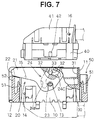
- This lever 20 is rotatably or pivotably supported by engaging the bearing holes 23 with support shafts 13 of the male housing 10. Specifically, the lever 20 is rotatable or pivotable between a connection start position (shown in FIGS. 2, 3, 7, 8) and a connection end position (shown in FIGS. 4 and 9) and also rotatable or pivotable from the connection start position to a standby position (shown in FIGS. 1 and 5) located substantially opposite from the connection end position.
- a rotational or pivotal range of the lever 20 between the connection start position (FIGS. 2 and 3) and the connection end position (FIGS. 4 and 9) is set such that the lever 20 does not interfere with the bracket 50 with the male housing 10 assembled with the bracket 50.
- the operation portion 22 of the lever 20 in the connection start position, is preferably substantially in contact with the upper end surface of a side wall portion 52 of the bracket 50 on the left side of FIGS. 7 and 8.
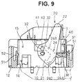
- the operation portion 22 is displaced to a position above the bracket 50 and the male housing 10 in a clockwise direction in FIGS. 9.
- the lever 20 when the lever 20 is rotated or pivoted to the standby position (FIGS. 1 and 5), the male housing 10 must be detached from the bracket 50.
- the operation portion 22 is displaced substantially downward in an area where there was or is to be arranged the left side wall 52 of the bracket 50 while being rotated or pivoted to the standby position.
- the operation portion 22 substantially reaches its standby position, it substantially comes into contact with the receiving portion 12 and any further rotation thereof is prevented (FIGS. 1 and 5).
- Each cam groove 24 is formed with a receiving inlet 24A for permitting the cam pins 32, 42 to enter the cam groove 24 with the lever 20 in its connection start position.
- a part of the cam groove 24 with which the cam pins 32, 42 are engaged or engageable while the lever 20 is rotated or pivoted from the connection start position to the connection end position is a substantially spiral or arcuate engaging area 24B for connection which gradually approaches the bearing hole 23 (support shaft 13).
- a part of the cam groove 24 extending from the receiving inlet 24A in a direction opposite from the engaging area 24B is a play area 24C (or loose movement area or clearance area) in the shape of a right arc about the bearing hole 23.
- the cam pins 32 of the moving plate 30 are relatively displaced in circumferential direction in the play areas 24C while the lever 20 is rotated or pivoted from the connection start position (FIGS. 7 and 8) to the standby position (FIG. 5). Since the play areas 24C are substantially in the shape of an arc substantially concentric with the center of rotation of the lever 20, the moving plate 30 and/or the female housing 40 will not move together with the lever 20.
- the male housing 10 is assembled with the lever 20 and the moving plate 30 as follows preferably at a factory from which it is shipped. First, the lever 20 is mounted. With the lever 20 in its connection start position, the moving plate 30 is fitted into the receptacle 11, and the cam pins 32 are introduced into the cam grooves 24 through the receiving inlets 24A. Thereafter, the lever 20 is rotated or pivoted from the connection start position to the standby position (see FIGS. 1 and 5). The assembling is completed in this manner and the male housing 10 is preferably shipped to a site of assembling. It should be noted that the lever 20 is temporarily held in the standby position by one or more locking projections 14 formed on the preferably outer surface of the male housing 10 and preferably interacting with the plate-shaped arm(s) 21 of the lever 20.
- the moving plate 30 While the lever 20 is rotated or pivoted to the standby position, the moving plate 30 is not displaced from its initial position since the cam pins 32 of the moving plate 30 are not engaged with the play areas 24C of the cam grooves 24. Further, since the cam pins 32 of the moving plate 30 are held from substantially opposing sides along the fitting direction FD or the vertical direction by the inner surface of the play areas 24C, a loose movement of the moving plate 30 with respect to the receptacle 11 is also prevented.
- the operation portion 22 of the lever 20 projects leftward from the left outer surface of the male housing 10 in the FIGS. 1 and 5 and is substantially in contact with the upper surface of the receiving portion 12. Accordingly, even if an other member pushes the operation portion 22 from above during shipment, this pushing force is received by the receiving portion 12. Thus, no excessive stress acts on the lever 20. Conversely, even if an upward pushing force from an other member acts on the receiving portion 12 from below, this pushing force is received by the receiving portion 12 without directly acting on the operation portion 22. Thus, in this case, a stress does not act on the lever 20, either.
- the operation portion 22 When the lever 20 is in its connection start position, the operation portion 22 thereof projects from the left side surface of the male housing 10 in an isolated manner (see FIGS. 2 and 3). In other words, the operation portion 22 is positioned at a distance from the male housing 10. Accordingly, if the male housing 10 is shipped in this state, other members may interfere with the operation portion 22 e.g. in vertical direction, thereby displacing the lever 20 from the connection start position or creating an excessive stress unless the lever 20 is displaced. Contrary to this, since the male housing 10 is shipped with the lever 20 in the standby position in this embodiment, there is no likelihood that the lever 20 is displaced or an excessive stress acts on the lever 20.
- the male housing 10 preferably transported to the assembling site in this state is connected with the female housing 40 after being assembled with the bracket 50.
- this process is described.
- the lever 20 in the standby position is rotated or pivoted in a connection direction CD (FIG. 8) toward the connection end position until the arms 21 are brought to substantially upright positions after passing the connection start position (see FIG. 6). In this substantially upright position the lever 20 does not substantially interfere with the bracket 50.
- the male housing 10 in this state is fitted into or onto the bracket 50 from below and then the lever 20 is returned to the connection start position (see FIGS. 2 and 7).
- the lever 20 preferably is temporarily held in the connection start position by locking projections 15 formed on the male housing 10.
- a wire cover 19 shown in FIGS. 2 to 4 is preferably mounted or mountable on the male housing 10 before the male housing 10 is assembled with the bracket 10.
- the female housing 40 preferably having the wire cover 41 mounted thereon is fitted into the receptacle 11 from a mating or fitting direction FD (FIG. 2), e.g. from above.
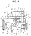
- the cam pins 42 of the female housing 40 substantially enter the cam grooves 24 through the receiving inlets 24A to be united or combined with the cam pins 32 of the moving plate 30 (see FIGS. 3 and 8).
- the lever 20 is rotated or pivoted toward the connection end position in this state, the female housing 40 and the moving plate 30 are drawn or pulled or forced or urged together into the back of the receptacle 11 by the engagement of the cam pins 32, 42 and the engaging areas 24B of the cam grooves 24.
- the housings 10, 40 are substantially properly connected (see FIGS. 4 and 9). In this connected state, the lever 20 is locked in the connection end position by being engaged with projections 16 formed on the wire cover 41.
- the cam grooves 24 of the lever 20 have the play areas 24C which are not engageable with the cam pins 32 of the moving plate 30. Accordingly, the moving plate 30 does not move together with the lever 20 while the lever 20 is rotated or pivoted from the connection start position to the standby position.
- the receptacle 11 needs not be enlarged in a direction of connection since the moving plate 30 will not be disengaged from the receptacle 11 even if the rotatable or pivotable range of the lever 20 is enlarged.
- cam pins 42 of the female housing 40 and the cam pins 32 of the moving plate 30 are engaged with the cam grooves 24 while being so united as to have a cylindrical shape, one cam groove 24 per arm 21 is sufficient and, as a result, the connector can be made smaller. If required even only one cam pin 42 of the female housing 40 and one cam pin 32 of the moving plain 30 may be arranged on the same side and engaged with one cam groove 24.
- the moving plate 30 Upon disconnecting the male housing 10 and the female housing 40 by rotating the lever 20 in a direction opposite to the connection direction CD, the moving plate 30 sustains the disconnection by being oriented by the guide wall portion 31 and substantially prevents the housings to be angled or jammed. Moreover the moving plate 30 preferably prevents the male terminals from being excessively bent during the disconnection.
Abstract
Description
- The present invention relates to a lever type connector.
- Some known lever type connectors are provided with a male housing having a receptacle and carrying a lever, a female housing to be fittable into the receptacle, and a moving plate movable in the receptacle.
- When the male and female connectors are to be connected, cam pins of the female housing and those of the moving plate are engaged with cam grooves of the lever with the lever held in a connection start position, and the lever is rotated to a connection end position in this state. Then, the female housing and the moving plate are drawn into the receptacle by the action of cams, thereby connecting the male and female connectors.
- The lever type connector of this type may be connected as follows. After the lever and the moving plate are assembled with the male housing at a factory, this housing is shipped to a site of assembling where it is assembled with a bracket and then connected with the female housing. In this case, a rotatable range of the lever during the connection is set such that the lever will not interfere the bracket.
- However, if there is a limit in the rotatable range of the lever, the lever may project from the outer surface of the male housing in an isolated manner before being assembled with the bracket. If the male housing is shipped in such a state, the lever may be broken by being interfered with by other members.
- In order to avoid this problem, the rotatable range of the lever may be made wider than its rotatable range during the connection of the housings so as to locate the lever in such a position where other members are unlikely to interfere with the lever when the male housing is shipped. However, since the cam pins of the moving plate are engaged with the cam grooves of the lever, the widening of the rotatable range of the lever means a larger moving stroke of the moving plate in the receptacle. Thus, there is a limit in widening the rotatable range of the lever. A forcible attempt to widen the rotatable range results the enlargement of the receptacle.
- In view of the above problems, an object of the present invention is to make the rotatable or pivotable range of a lever wider than its rotatable or pivotable range during the connection of male and female housings without changing a moving stroke of a moving plate.
- This object is solved according to the invention by a lever type connector according to
claim 1. Preferred embodiments of the invention are subject of the dependent claims.
According to the invention, there is provided a lever type connector, comprising: - a male housing having a receptacle,
- a female housing at least partially fittable or insertable into the receptacle and having one or more cam pins,
- a moving plate movable along a fitting direction in the receptacle and having one or more cam pins, and
- a lever having one or more cam grooves engageable with the cam pins and
rotatably or pivotably supported on the male housing,
wherein: - the female housing and the moving plate are drawn into the receptacle (in the fitting direction) by rotating or pivoting the lever (in a connection direction) from the connection start position to the connection end position with the cam pins and the cam grooves engaged with each other,
- the lever is permitted to rotate or pivote (in a direction opposite to the connection direction) from the connection start position to a standby position being preferably opposite from the connection end position, and
- the cam grooves are each provided with a play area which is substantially not in engagement (preferably in a rotational or pivotal direction) with the corresponding cam pin of the moving plate during the rotation or pivotal movement of the lever (in a direction opposite to the connection direction) from the connection start position toward the standby position.
-
- Since the cam grooves of the lever and the cam pins of the moving plates are not engaged with each other during the rotation of the lever from the connection start position and the standby position, the moving plate will not move together with the lever.
- According to a preferred embodiment of the invention, the male housing is formed with a receiving portion for receiving the lever when the lever is rotated to the standby position.
- With the lever rotated to the standby position and received by the receiving portion, a contact force given to the lever from an other member is received by the receiving portion. Accordingly, no excessive stress acts on the lever.
- Preferably, the receiving portion projects from the male housing such that the lever cannot be externally reached in a direction opposite to the fitting direction. Accordingly, the lever cannot be inadvertently displaced (e.g. during shipping) by an external object hitting the connector from a side opposed to the mating side (e.g. from below in the FIGURES).
- Further preferably, the cam pins of the female housing and those of the moving plate are unitable and each pair of the united cam pins are engaged with the corresponding cam groove.
- Since each pair of the cam pins of the moving plate and the female connector housing are engaged with the corresponding cam grooves while being united, one cam groove is sufficient for one pair of the cam pins of the moving plate and the female connector. As a result, the lever can be made smaller.
- Most preferably, the cam groove comprises a receiving inlet for receiving the corresponding cam pin upon mating the female housing with the male housing.
- According to a further preferred embodiment, the male housing and/or the female housing are provided with locking means for temporarily locking the lever in the connection start position, the connection end position and/or the standby position.
- Preferably, the cam pins of the moving plate are substantially held by the inner surfaces of the play areas along the fitting direction, preferably when the lever is positioned in the standby position.
- Thus a loose movement of the moving plate with respect to the receptacle is prevented.
- Further preferably, the male housing is fittable into or onto a bracket preferably with the lever being positioned in a substantially upright position.
- Still further preferably, the lever comes into contact with the bracket in a direction opposite to the connection direction when the lever is positioned in the connection start position.
- Most preferably, the moving plate comprises a guide wall portion for guiding the movement of the moving plate inside the receptacle of the male housing.
- These and other objects, features and advantages of the present invention will become more apparent upon a reading of the following detailed description and accompanying drawings in which:
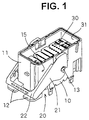
- FIG. 1 is a perspective view showing a state of one embodiment where a lever is in a standby position,
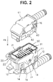
- FIG. 2 is a perspective view showing a state where the lever is in a connection start position,
- FIG. 3 is a perspective view showing a state where the connection of male and female housings is started,
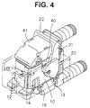
- FIG. 4 is a perspective view showing a state where the connection of the male and female housings is completed,
- FIG. 5 is a side view partly in section showing a state where the lever is in the standby position,
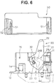
- FIG. 6 is a side view partly in section showing a state where the lever is in such a position that the male housing can be assembled with a bracket,
- FIG. 7 is a side view partly in section showing a state where the lever is in the connection start position,
- FIG. 8 is a side view partly in section showing a state where the connection of the male and female housings is started,
- FIG. 9 is a side view partly in section showing a state where the connection of the male and female housings is completed,
- FIG. 10 is an enlarged partial view showing a state where a cam pin of the female housing and a cam pin of a moving plate are separated, and
- FIG. 11 is an enlarged partial view showing a state where the cam pin of the female housing and the cam pin of the moving plate are united.
-
- Hereafter, one embodiment of the invention is described with reference to FIGS. 1 to 11.
- A lever type connector according to this embodiment is comprised of a
male housing 10, alever 20, a movingplate 30 and afemale housing 40. - The
male housing 10 has areceptacle 11 which is open towards a mating side or upward and has a substantially rectangular cross section, and a plurality of unillustrated male terminal fittings project upward inside thereceptacle 11. Themale housing 10 is connected or connectable with thefemale housing 40 while being assembled with abracket 50 substantially surrounding it. Themale housing 10 is assembled with thebracket 50 by being fitted or arranged thereinto or thereonto, preferably from below and, in its assembled state, has its movement in an assembling direction (upward direction) restricted by receivingportions 12 projecting from the outer surface thereof and is locked or lockable byelastic locking pieces 51 provided preferably on the inner side of thebracket 50. - In the
receptacle 11 is accommodated or accommodatable themoving plate 30 which is movable upward and downward with the respective male terminal fittings penetrated or displaceable therethrough. The movingplate 30 has a substantially tubularguide wall portion 31 on its periphery. By arranging or mating thisguide wall portion 31 substantially along or on (portions of) the inner surface of thereceptacle 11, the movingplate 30 can be moved while being held or oriented or positioned in a specified orientation or position. A pair ofcam pins 32 project from the outer surface of each of the lateral or left and right walls of theguide wall portion 31 of themoving plate 30. The pair ofcam pins 32 are preferably so formed as to have a comb-like shape or one or more notches or recesses by cutting a center portion of a cylinder as enlargedly shown in FIGS. 10 and 11, and acam pin 42 of thefemale housing 40 is fitted or fittable into aclearance 33 between thecam pins 32. - The
female housing 40 is so shaped and dimensioned as to be fittable into thereceptacle 11, and awire cover 41 is mounted or mountable on the upper surface thereof. One each of thecam pins 42 preferably projects from the lateral or left and right side surfaces of thefemale housing 40 or the surface thereof opposed to the mating surface for mating thefemale housing 40 with themale housing 10. The cam pins 42 preferably have a substantially oval-shaped or rounded cross section, and are fitted or fittable between the comb-shaped cam pins 32 of the movingplate 30 preferably from above to be united or mated or to interact with the cam pins 32. An assembly of the united cam pins 32, 42 has a substantially cylindrical shape as a whole (see FIG. 11). Such cam pins 42 in their united state are engaged incam grooves 24 of thelever 20 to be described later. - The
lever 20 is shaped such that the leading ends of a pair of plate-shapedarms 21 are connected by anoperation portion 22. At the base end portion of eacharm 21 are formed abearing hole 23 and a cam groove orrecess 24 substantially surrounding the bearinghole 23. Thislever 20 is rotatably or pivotably supported by engaging the bearing holes 23 withsupport shafts 13 of themale housing 10. Specifically, thelever 20 is rotatable or pivotable between a connection start position (shown in FIGS. 2, 3, 7, 8) and a connection end position (shown in FIGS. 4 and 9) and also rotatable or pivotable from the connection start position to a standby position (shown in FIGS. 1 and 5) located substantially opposite from the connection end position. - A rotational or pivotal range of the
lever 20 between the connection start position (FIGS. 2 and 3) and the connection end position (FIGS. 4 and 9) is set such that thelever 20 does not interfere with thebracket 50 with themale housing 10 assembled with thebracket 50. In other words, in the connection start position, theoperation portion 22 of thelever 20 is preferably substantially in contact with the upper end surface of aside wall portion 52 of thebracket 50 on the left side of FIGS. 7 and 8. When thelever 20 is rotated or pivoted toward the connection end position, theoperation portion 22 is displaced to a position above thebracket 50 and themale housing 10 in a clockwise direction in FIGS. 9. - Further, when the
lever 20 is rotated or pivoted to the standby position (FIGS. 1 and 5), themale housing 10 must be detached from thebracket 50. In other words, theoperation portion 22 is displaced substantially downward in an area where there was or is to be arranged theleft side wall 52 of thebracket 50 while being rotated or pivoted to the standby position. When theoperation portion 22 substantially reaches its standby position, it substantially comes into contact with the receivingportion 12 and any further rotation thereof is prevented (FIGS. 1 and 5). - Each
cam groove 24 is formed with a receivinginlet 24A for permitting the cam pins 32, 42 to enter thecam groove 24 with thelever 20 in its connection start position. A part of thecam groove 24 with which the cam pins 32, 42 are engaged or engageable while thelever 20 is rotated or pivoted from the connection start position to the connection end position is a substantially spiral or arcuate engagingarea 24B for connection which gradually approaches the bearing hole 23 (support shaft 13). When thelever 20 is rotated or pivoted from the connection start position (FIGS. 7 and 8) to the connection end position (FIG. 9), thefemale housing 40 and the movingplate 30 are drawn or pulled or forced at least partially into thereceptacle 11 by the engagement of the engagingareas 24B and the cam pins 32, 42. When thelever 20 reaches the connection end position (FIGS. 4 and 9), thehousings - On the other hand, a part of the
cam groove 24 extending from the receivinginlet 24A in a direction opposite from the engagingarea 24B is aplay area 24C (or loose movement area or clearance area) in the shape of a right arc about the bearinghole 23. The cam pins 32 of the movingplate 30 are relatively displaced in circumferential direction in theplay areas 24C while thelever 20 is rotated or pivoted from the connection start position (FIGS. 7 and 8) to the standby position (FIG. 5). Since theplay areas 24C are substantially in the shape of an arc substantially concentric with the center of rotation of thelever 20, the movingplate 30 and/or thefemale housing 40 will not move together with thelever 20. - Next, the assembling, mounting and/or action of this embodiment is described.
- The
male housing 10 is assembled with thelever 20 and the movingplate 30 as follows preferably at a factory from which it is shipped. First, thelever 20 is mounted. With thelever 20 in its connection start position, the movingplate 30 is fitted into thereceptacle 11, and the cam pins 32 are introduced into thecam grooves 24 through the receivinginlets 24A. Thereafter, thelever 20 is rotated or pivoted from the connection start position to the standby position (see FIGS. 1 and 5). The assembling is completed in this manner and themale housing 10 is preferably shipped to a site of assembling. It should be noted that thelever 20 is temporarily held in the standby position by one ormore locking projections 14 formed on the preferably outer surface of themale housing 10 and preferably interacting with the plate-shaped arm(s) 21 of thelever 20. - While the
lever 20 is rotated or pivoted to the standby position, the movingplate 30 is not displaced from its initial position since the cam pins 32 of the movingplate 30 are not engaged with theplay areas 24C of thecam grooves 24. Further, since the cam pins 32 of the movingplate 30 are held from substantially opposing sides along the fitting direction FD or the vertical direction by the inner surface of theplay areas 24C, a loose movement of the movingplate 30 with respect to thereceptacle 11 is also prevented. - With the
lever 20 located in the standby position, theoperation portion 22 of thelever 20 projects leftward from the left outer surface of themale housing 10 in the FIGS. 1 and 5 and is substantially in contact with the upper surface of the receivingportion 12. Accordingly, even if an other member pushes theoperation portion 22 from above during shipment, this pushing force is received by the receivingportion 12. Thus, no excessive stress acts on thelever 20. Conversely, even if an upward pushing force from an other member acts on the receivingportion 12 from below, this pushing force is received by the receivingportion 12 without directly acting on theoperation portion 22. Thus, in this case, a stress does not act on thelever 20, either. - When the
lever 20 is in its connection start position, theoperation portion 22 thereof projects from the left side surface of themale housing 10 in an isolated manner (see FIGS. 2 and 3). In other words, theoperation portion 22 is positioned at a distance from themale housing 10. Accordingly, if themale housing 10 is shipped in this state, other members may interfere with theoperation portion 22 e.g. in vertical direction, thereby displacing thelever 20 from the connection start position or creating an excessive stress unless thelever 20 is displaced. Contrary to this, since themale housing 10 is shipped with thelever 20 in the standby position in this embodiment, there is no likelihood that thelever 20 is displaced or an excessive stress acts on thelever 20. - The
male housing 10 preferably transported to the assembling site in this state is connected with thefemale housing 40 after being assembled with thebracket 50. Hereafter, this process is described. - First, the
lever 20 in the standby position is rotated or pivoted in a connection direction CD (FIG. 8) toward the connection end position until thearms 21 are brought to substantially upright positions after passing the connection start position (see FIG. 6). In this substantially upright position thelever 20 does not substantially interfere with thebracket 50. Subsequently, themale housing 10 in this state is fitted into or onto thebracket 50 from below and then thelever 20 is returned to the connection start position (see FIGS. 2 and 7). Then, thelever 20 preferably is temporarily held in the connection start position by lockingprojections 15 formed on themale housing 10. It should be noted that awire cover 19 shown in FIGS. 2 to 4 is preferably mounted or mountable on themale housing 10 before themale housing 10 is assembled with thebracket 10. - Subsequently, in this state, the
female housing 40 preferably having thewire cover 41 mounted thereon is fitted into thereceptacle 11 from a mating or fitting direction FD (FIG. 2), e.g. from above. Then, the cam pins 42 of thefemale housing 40 substantially enter thecam grooves 24 through the receivinginlets 24A to be united or combined with the cam pins 32 of the moving plate 30 (see FIGS. 3 and 8). If thelever 20 is rotated or pivoted toward the connection end position in this state, thefemale housing 40 and the movingplate 30 are drawn or pulled or forced or urged together into the back of thereceptacle 11 by the engagement of the cam pins 32, 42 and the engagingareas 24B of thecam grooves 24. When thelever 20 reaches the connection end position, thehousings lever 20 is locked in the connection end position by being engaged withprojections 16 formed on thewire cover 41. - As described above, the
cam grooves 24 of thelever 20 have theplay areas 24C which are not engageable with the cam pins 32 of the movingplate 30. Accordingly, the movingplate 30 does not move together with thelever 20 while thelever 20 is rotated or pivoted from the connection start position to the standby position. - Further, the
receptacle 11 needs not be enlarged in a direction of connection since the movingplate 30 will not be disengaged from thereceptacle 11 even if the rotatable or pivotable range of thelever 20 is enlarged. - Since the cam pins 42 of the
female housing 40 and the cam pins 32 of the movingplate 30 are engaged with thecam grooves 24 while being so united as to have a cylindrical shape, onecam groove 24 perarm 21 is sufficient and, as a result, the connector can be made smaller. If required even only onecam pin 42 of thefemale housing 40 and onecam pin 32 of the moving plain 30 may be arranged on the same side and engaged with onecam groove 24. - Upon disconnecting the
male housing 10 and thefemale housing 40 by rotating thelever 20 in a direction opposite to the connection direction CD, the movingplate 30 sustains the disconnection by being oriented by theguide wall portion 31 and substantially prevents the housings to be angled or jammed. Moreover the movingplate 30 preferably prevents the male terminals from being excessively bent during the disconnection. - The present invention is not limited to the described and illustrated embodiment, but the following embodiments are also embraced by the technical scope of the present invention as defined in the claims. Besides the following embodiments, a variety of other changes can be made without departing from the scope and spirit of the invention as defined in the claims.
- (1) The male housing is formed with the receiving portion in the foregoing embodiment. However, according to the invention, the receiving portion may be dispensed with if there is no likelihood that the lever is interfered with by other members in the standby position.
- (2) In the foregoing embodiment, the cam pin of the female housing and that of the moving plate are engaged with the one cam groove while being united. However, according to the invention, each arm may be provided with two cam grooves, so that the cam pin of the female housing and that of the moving plate can be separately engaged with the respective cam grooves.
- (3) Although the bracket is assembled with the male housing after the shipment of the male housing to the assembling site in the foregoing embodiment, it may be already assembled with the male housing before shipment.
- (4) Even though the invention was described with reference to an at least partially assembled lever type connector, the invention is meant to include also a lever type connector kit, i.e. a lever type connector according to the claims in its disassembled state.
- (5) Even though the invention was described with reference to cam grooves being provided on the lever and cam pins being provided on the female housing and moving plate, the invention is meant also to include embodiments in which the cam grooves are provided on the female housing and/or moving plate and the cam pins are provided on the lever.
-
-
- 10
- Male Housing
- 11
- Receptacle
- 12
- Receiving Portion
- 20
- Lever
- 24
- Cam Groove
- 24C
- Play Area
- 30
- Moving Plate
- 32
- Cam Pin of the Moving Plate
- 40
- Female Housing
- 42
- Cam Pin of the Female Housing
Claims (10)
- A lever type connector, comprising:a male housing (10) having a receptacle (11),a female housing (40) at least partially fittable into the receptacle (11) and having one or more cam pins (42),a moving plate (30) movable along a fitting (or mating) direction (FD) in the receptacle (11) and having one or more cam pins (32), anda lever (20) having one or more cam grooves (24) engageable with the housing cam pins (42) and rotatably or pivotably supported on the male housing (10),
wherein:the female housing (40) and the moving plate (30) are drawn in the fitting direction (FD) into the receptacle (11) by rotating or pivoting the lever (20) in a connection direction (CD) from the connection start position (FIG. 2; 3; 7; 8) to the connection end position (FIG. 4; 9) with the cam pins (32, 42) and the cam grooves (24) engaged with each other,the lever (20) is permitted to rotate or pivote in a direction opposite to the connection direction (CD) from the connection start position (FIG. 2; 3; 7; 8) to a standby position (FIG. 1; 5) being preferably opposite from the connection end position (FIG. 4; 9), andthe cam grooves (24) are each provided with a play area (24C) which is substantially not in engagement with the corresponding cam pin (32) of the moving plate (30) during the rotation or pivotal movement of the lever (20) in a direction opposite to the connection direction (CD) from the connection start position (FIG. 2; 3; 7; 8) toward the standby position (FIG. 1; 5). - A lever type connector according to claim 1, wherein the male housing (10) is formed with a receiving portion (12) for receiving the lever (20) when the lever (20) is rotated to the standby position (FIG. 1; 5).
- A lever type connector according to claim 2, wherein the receiving portion (12) projects from the male housing (10) such that the lever (20) cannot be externally reached in a direction opposite to the fitting direction.
- A lever type connector according to one or more of the preceding claims, wherein the cam pins (42) of the female housing (40) and those (32) of the moving plate (30) are unitable (FIG. 11) and each pair of the united cam pins (32, 42) are engaged with the corresponding cam groove (24).
- A lever type connector according to one or more of the preceding claims, wherein the cam groove (24) comprises a receiving inlet (24A) for receiving the corresponding cam pin (42; 32) upon mating the female housing (40) with the male housing (10).
- A lever type connector according to one or more of the preceding claims, wherein the male housing (10) and/or the female housing (40) are provided with locking means (15; 16; 14) for temporarily locking the lever (20) in the connection start position (FIG. 2; 3; 7; 8), the connection end position (FIG. 4; 9) and/or the standby position (FIG. 1; 5).
- A lever type connector according to one or more of the preceding claims, wherein the cam pins (32) of the moving plate (30) are substantially held by the inner surfaces of the play areas (24C) along the fitting direction (FD), preferably when the lever (20) is positioned in the standby position (FIG. 1; 5).
- A lever type connector according to one or more of the preceding claims, wherein the male housing (10) is fittable into or onto a bracket (50) preferably with the lever (20) being positioned in a substantially upright position (FIG. 6).
- A lever type connector according to claim 8, wherein the lever (20) comes into contact with the bracket (50) in a direction opposite to the connection direction (CD) when the lever is positioned in the connection start position (FIG. 7; 8).
- A lever type connector according to one or more of the preceding claims, wherein the moving plate (30) comprises a guide wall portion (31) for guiding the movement of the moving plate (30) inside the receptacle (11) of the male housing (10).
Applications Claiming Priority (2)
| Application Number | Priority Date | Filing Date | Title |
|---|---|---|---|
| JP12218598 | 1998-05-01 | ||
| JP12218598A JP3319387B2 (en) | 1998-05-01 | 1998-05-01 | Lever connector |
Publications (3)
| Publication Number | Publication Date |
|---|---|
| EP0954062A2 true EP0954062A2 (en) | 1999-11-03 |
| EP0954062A3 EP0954062A3 (en) | 2002-01-23 |
| EP0954062B1 EP0954062B1 (en) | 2003-07-16 |
Family
ID=14829691
Family Applications (1)
| Application Number | Title | Priority Date | Filing Date |
|---|---|---|---|
| EP99107499A Expired - Lifetime EP0954062B1 (en) | 1998-05-01 | 1999-04-30 | A lever type connector |
Country Status (5)
| Country | Link |
|---|---|
| US (1) | US6193531B1 (en) |
| EP (1) | EP0954062B1 (en) |
| JP (1) | JP3319387B2 (en) |
| CN (1) | CN1158727C (en) |
| DE (1) | DE69909550T2 (en) |
Cited By (5)
| Publication number | Priority date | Publication date | Assignee | Title |
|---|---|---|---|---|
| KR20010089269A (en) * | 2000-03-20 | 2001-09-29 | 루이스 에이. 헥트 | Lever type electrical connector |
| EP1257013A1 (en) * | 2001-05-07 | 2002-11-13 | Sumitomo Wiring Systems, Ltd. | A terminal fitting |
| WO2007064999A1 (en) * | 2005-12-01 | 2007-06-07 | Molex Incorporated | Lever type electrical connector |
| EP1981128A1 (en) | 2007-04-09 | 2008-10-15 | Sumitomo Wiring Systems, Ltd. | A lever-type connector and connector assembly |
| WO2011015532A1 (en) * | 2009-08-06 | 2011-02-10 | Tyco Electronics Amp Gmbh | Combined electrical connector with tolerance compensation |
Families Citing this family (29)
| Publication number | Priority date | Publication date | Assignee | Title |
|---|---|---|---|---|
| JP4156774B2 (en) * | 2000-05-01 | 2008-09-24 | 住友電装株式会社 | Lever type connector |
| JP3961228B2 (en) * | 2001-03-28 | 2007-08-22 | 矢崎総業株式会社 | Lever fitting type connector |
| JP3985570B2 (en) * | 2002-04-08 | 2007-10-03 | 住友電装株式会社 | Electrical junction box |
| US6739896B2 (en) * | 2002-05-09 | 2004-05-25 | American Megatrends, Inc. | Cable retention apparatus |
| EP2063499A3 (en) * | 2002-09-19 | 2009-11-11 | Sumitomo Wiring Systems, Ltd. | A connector assembly, connector, connector assembling construction and method of assembling them |
| DE102005050625B4 (en) * | 2004-10-22 | 2011-07-28 | Sumitomo Wiring Systems, Ltd., Mie | Connector and connector assembly |
| JP4597852B2 (en) * | 2005-12-07 | 2010-12-15 | 矢崎総業株式会社 | connector |
| JP4622930B2 (en) * | 2006-04-20 | 2011-02-02 | 住友電装株式会社 | Lever type connector |
| JP4966625B2 (en) * | 2006-10-27 | 2012-07-04 | 矢崎総業株式会社 | connector |
| JP5012086B2 (en) * | 2007-02-26 | 2012-08-29 | 住友電装株式会社 | connector |
| US7559779B1 (en) | 2008-05-14 | 2009-07-14 | Cinch Connectors, Inc. | Electrical connector |
| JP5217994B2 (en) * | 2008-12-10 | 2013-06-19 | 住友電装株式会社 | Lever type connector |
| JP5534501B2 (en) * | 2009-10-09 | 2014-07-02 | 矢崎総業株式会社 | Lever type connector |
| JP5454446B2 (en) * | 2010-10-08 | 2014-03-26 | 住友電装株式会社 | connector |
| JP2012109174A (en) * | 2010-11-19 | 2012-06-07 | Sumitomo Wiring Syst Ltd | Lever-type connector |
| CN102074841B (en) * | 2010-11-24 | 2013-04-24 | 胡连精密股份有限公司 | Electric coupler |
| US9431749B2 (en) * | 2014-06-30 | 2016-08-30 | Tyco Electronics Corporation | Electrical connector assembly comprising an array of elongated electrical contacts |
| US9455521B2 (en) * | 2014-12-03 | 2016-09-27 | Hyundai Motor Company | Lever type connector |
| US9520675B2 (en) * | 2014-12-04 | 2016-12-13 | Hyundai Motor Company | Lever type connector |
| JP6185960B2 (en) * | 2015-05-27 | 2017-08-23 | 矢崎総業株式会社 | connector |
| US10246034B2 (en) * | 2016-12-08 | 2019-04-02 | Sumitomo Wiring Systems, Ltd. | Power distribution center mounting assembly |
| JP6852606B2 (en) * | 2017-07-18 | 2021-03-31 | 住友電装株式会社 | Lever type connector |
| JP6924386B2 (en) * | 2018-01-25 | 2021-08-25 | 住友電装株式会社 | Lever type connector |
| EP3544125B1 (en) * | 2018-03-19 | 2022-12-07 | Tyco Electronics AMP Korea Co., Ltd. | Connector assembly comprising a male connector |
| JP6944410B2 (en) * | 2018-06-06 | 2021-10-06 | 住友電装株式会社 | Lever type connector |
| JP6933190B2 (en) * | 2018-06-06 | 2021-09-08 | 住友電装株式会社 | Lever type connector |
| EP3806246A4 (en) | 2018-06-06 | 2021-07-14 | Sumitomo Wiring Systems, Ltd. | Lever-type connector |
| JP7021150B2 (en) * | 2019-05-27 | 2022-02-16 | 矢崎総業株式会社 | How to assemble the lever type connector and the lever type connector |
| KR20220067228A (en) * | 2020-11-17 | 2022-05-24 | 현대자동차주식회사 | Wiring connector assembly |
Citations (6)
| Publication number | Priority date | Publication date | Assignee | Title |
|---|---|---|---|---|
| US5230635A (en) * | 1991-06-25 | 1993-07-27 | Yazaki Corporation | Connector with lever |
| US5263871A (en) * | 1991-08-27 | 1993-11-23 | Yazaki Corporation | Device for interconnecting connectors |
| EP0579428A1 (en) * | 1992-07-13 | 1994-01-19 | Sumitomo Wiring Systems, Ltd. | Lever type connector |
| EP0606151A2 (en) * | 1993-01-06 | 1994-07-13 | Sumitomo Wiring Systems, Ltd. | Connector using lever action |
| US5476390A (en) * | 1993-03-17 | 1995-12-19 | Yazaki Corporation | Lever-coupling type connector |
| EP0722203A1 (en) * | 1995-01-16 | 1996-07-17 | Molex Incorporated | Electrical connector assembly with improved camming system |
Family Cites Families (3)
| Publication number | Priority date | Publication date | Assignee | Title |
|---|---|---|---|---|
| JP2624049B2 (en) | 1991-09-13 | 1997-06-25 | 住友電装株式会社 | connector |
| JP2568730Y2 (en) * | 1992-12-24 | 1998-04-15 | 住友電装株式会社 | Lever connector |
| JP2940894B2 (en) * | 1993-02-24 | 1999-08-25 | 矢崎総業株式会社 | Lever connector |
-
1998
- 1998-05-01 JP JP12218598A patent/JP3319387B2/en not_active Expired - Lifetime
-
1999
- 1999-04-23 CN CNB991058623A patent/CN1158727C/en not_active Expired - Lifetime
- 1999-04-26 US US09/299,442 patent/US6193531B1/en not_active Expired - Lifetime
- 1999-04-30 EP EP99107499A patent/EP0954062B1/en not_active Expired - Lifetime
- 1999-04-30 DE DE69909550T patent/DE69909550T2/en not_active Expired - Lifetime
Patent Citations (6)
| Publication number | Priority date | Publication date | Assignee | Title |
|---|---|---|---|---|
| US5230635A (en) * | 1991-06-25 | 1993-07-27 | Yazaki Corporation | Connector with lever |
| US5263871A (en) * | 1991-08-27 | 1993-11-23 | Yazaki Corporation | Device for interconnecting connectors |
| EP0579428A1 (en) * | 1992-07-13 | 1994-01-19 | Sumitomo Wiring Systems, Ltd. | Lever type connector |
| EP0606151A2 (en) * | 1993-01-06 | 1994-07-13 | Sumitomo Wiring Systems, Ltd. | Connector using lever action |
| US5476390A (en) * | 1993-03-17 | 1995-12-19 | Yazaki Corporation | Lever-coupling type connector |
| EP0722203A1 (en) * | 1995-01-16 | 1996-07-17 | Molex Incorporated | Electrical connector assembly with improved camming system |
Cited By (7)
| Publication number | Priority date | Publication date | Assignee | Title |
|---|---|---|---|---|
| KR20010089269A (en) * | 2000-03-20 | 2001-09-29 | 루이스 에이. 헥트 | Lever type electrical connector |
| EP1257013A1 (en) * | 2001-05-07 | 2002-11-13 | Sumitomo Wiring Systems, Ltd. | A terminal fitting |
| WO2007064999A1 (en) * | 2005-12-01 | 2007-06-07 | Molex Incorporated | Lever type electrical connector |
| US7267564B2 (en) | 2005-12-01 | 2007-09-11 | Molex Incorporated | Lever type electrical connector |
| EP1981128A1 (en) | 2007-04-09 | 2008-10-15 | Sumitomo Wiring Systems, Ltd. | A lever-type connector and connector assembly |
| CN101335403B (en) * | 2007-04-09 | 2011-04-06 | 住友电装株式会社 | Lever-type connector and connector assembly |
| WO2011015532A1 (en) * | 2009-08-06 | 2011-02-10 | Tyco Electronics Amp Gmbh | Combined electrical connector with tolerance compensation |
Also Published As
| Publication number | Publication date |
|---|---|
| DE69909550T2 (en) | 2004-05-13 |
| CN1234632A (en) | 1999-11-10 |
| CN1158727C (en) | 2004-07-21 |
| EP0954062A3 (en) | 2002-01-23 |
| JPH11317255A (en) | 1999-11-16 |
| DE69909550D1 (en) | 2003-08-21 |
| JP3319387B2 (en) | 2002-08-26 |
| US6193531B1 (en) | 2001-02-27 |
| EP0954062B1 (en) | 2003-07-16 |
Similar Documents
| Publication | Publication Date | Title |
|---|---|---|
| EP0954062B1 (en) | A lever type connector | |
| EP0843386A1 (en) | A lever connector | |
| US5575671A (en) | Lever-type connector | |
| US7670157B2 (en) | Lever connector | |
| CA2494457C (en) | Electrical connector assembly with connection assurance features | |
| JP3152155B2 (en) | Lever connector | |
| CN103636077B (en) | Lever-fitting-type connector | |
| JP4236034B2 (en) | Electrical connector | |
| US20020064987A1 (en) | Low insertion force type connector | |
| JPH07230850A (en) | Lever type connector | |
| JP2003234146A (en) | Electric connector | |
| JP3023868B2 (en) | Lever connection type connector | |
| CN103636076A (en) | Lever-fitting-type connector | |
| US20210013675A1 (en) | Lever-type connector | |
| US6863463B2 (en) | Lever-type connector and connector assembly | |
| CN103636075B (en) | Lever-fitting-type connector | |
| EP1253677B1 (en) | Connector assembly | |
| US5427539A (en) | Lever type connector | |
| JP3244034B2 (en) | Lever connector | |
| JP2004319140A (en) | Connector | |
| JPH09147973A (en) | Lever type connector | |
| JP2006185772A (en) | Lever type connector | |
| JP3488197B2 (en) | Lever mating connector | |
| JP3449947B2 (en) | Electric junction box lever structure | |
| JP3520684B2 (en) | Lever type connector |
Legal Events
| Date | Code | Title | Description |
|---|---|---|---|
| PUAI | Public reference made under article 153(3) epc to a published international application that has entered the european phase |
Free format text: ORIGINAL CODE: 0009012 |
|
| 17P | Request for examination filed |
Effective date: 19990520 |
|
| AK | Designated contracting states |
Kind code of ref document: A2 Designated state(s): AT BE CH CY DE DK ES FI FR GB GR IE IT LI LU MC NL PT SE Kind code of ref document: A2 Designated state(s): DE FR |
|
| AX | Request for extension of the european patent |
Free format text: AL;LT;LV;MK;RO;SI |
|
| PUAL | Search report despatched |
Free format text: ORIGINAL CODE: 0009013 |
|
| AK | Designated contracting states |
Kind code of ref document: A3 Designated state(s): AT BE CH CY DE DK ES FI FR GB GR IE IT LI LU MC NL PT SE |
|
| AX | Request for extension of the european patent |
Free format text: AL;LT;LV;MK;RO;SI |
|
| 17Q | First examination report despatched |
Effective date: 20020523 |
|
| GRAH | Despatch of communication of intention to grant a patent |
Free format text: ORIGINAL CODE: EPIDOS IGRA |
|
| AKX | Designation fees paid |
Free format text: DE FR |
|
| GRAH | Despatch of communication of intention to grant a patent |
Free format text: ORIGINAL CODE: EPIDOS IGRA |
|
| GRAA | (expected) grant |
Free format text: ORIGINAL CODE: 0009210 |
|
| AK | Designated contracting states |
Designated state(s): DE FR |
|
| REG | Reference to a national code |
Ref country code: IE Ref legal event code: FG4D |
|
| REF | Corresponds to: |
Ref document number: 69909550 Country of ref document: DE Date of ref document: 20030821 Kind code of ref document: P |
|
| ET | Fr: translation filed | ||
| PLBE | No opposition filed within time limit |
Free format text: ORIGINAL CODE: 0009261 |
|
| STAA | Information on the status of an ep patent application or granted ep patent |
Free format text: STATUS: NO OPPOSITION FILED WITHIN TIME LIMIT |
|
| 26N | No opposition filed |
Effective date: 20040419 |
|
| REG | Reference to a national code |
Ref country code: IE Ref legal event code: MM4A |
|
| REG | Reference to a national code |
Ref country code: FR Ref legal event code: PLFP Year of fee payment: 18 |
|
| REG | Reference to a national code |
Ref country code: FR Ref legal event code: PLFP Year of fee payment: 19 |
|
| REG | Reference to a national code |
Ref country code: FR Ref legal event code: PLFP Year of fee payment: 20 |
|
| PGFP | Annual fee paid to national office [announced via postgrant information from national office to epo] |
Ref country code: FR Payment date: 20180315 Year of fee payment: 20 |
|
| PGFP | Annual fee paid to national office [announced via postgrant information from national office to epo] |
Ref country code: DE Payment date: 20180417 Year of fee payment: 20 |
|
| REG | Reference to a national code |
Ref country code: DE Ref legal event code: R071 Ref document number: 69909550 Country of ref document: DE |