EP0954040A1 - Safety device and secondary battery using the same - Google Patents
Safety device and secondary battery using the same Download PDFInfo
- Publication number
- EP0954040A1 EP0954040A1 EP99303274A EP99303274A EP0954040A1 EP 0954040 A1 EP0954040 A1 EP 0954040A1 EP 99303274 A EP99303274 A EP 99303274A EP 99303274 A EP99303274 A EP 99303274A EP 0954040 A1 EP0954040 A1 EP 0954040A1
- Authority
- EP
- European Patent Office
- Prior art keywords
- thin plate
- safety device
- plate
- pressure chamber
- reference pressure
- Prior art date
- Legal status (The legal status is an assumption and is not a legal conclusion. Google has not performed a legal analysis and makes no representation as to the accuracy of the status listed.)
- Granted
Links
- 239000000463 material Substances 0.000 claims abstract description 39
- 238000000034 method Methods 0.000 claims description 50
- 125000006850 spacer group Chemical group 0.000 claims description 30
- 229910010293 ceramic material Inorganic materials 0.000 claims description 17
- 239000011521 glass Substances 0.000 claims description 12
- 238000005245 sintering Methods 0.000 claims description 10
- 239000006112 glass ceramic composition Substances 0.000 claims description 9
- 239000008151 electrolyte solution Substances 0.000 claims description 6
- 230000002093 peripheral effect Effects 0.000 claims description 4
- 238000004519 manufacturing process Methods 0.000 description 29
- 230000008569 process Effects 0.000 description 28
- 239000000758 substrate Substances 0.000 description 25
- 238000010276 construction Methods 0.000 description 17
- MCMNRKCIXSYSNV-UHFFFAOYSA-N Zirconium dioxide Chemical compound O=[Zr]=O MCMNRKCIXSYSNV-UHFFFAOYSA-N 0.000 description 12
- 230000007246 mechanism Effects 0.000 description 11
- PNEYBMLMFCGWSK-UHFFFAOYSA-N aluminium oxide Inorganic materials [O-2].[O-2].[O-2].[Al+3].[Al+3] PNEYBMLMFCGWSK-UHFFFAOYSA-N 0.000 description 10
- 230000002159 abnormal effect Effects 0.000 description 9
- 230000015572 biosynthetic process Effects 0.000 description 7
- 229910052751 metal Inorganic materials 0.000 description 7
- 239000002184 metal Substances 0.000 description 7
- 229910001416 lithium ion Inorganic materials 0.000 description 6
- 238000007639 printing Methods 0.000 description 6
- 239000002002 slurry Substances 0.000 description 6
- HBBGRARXTFLTSG-UHFFFAOYSA-N Lithium ion Chemical compound [Li+] HBBGRARXTFLTSG-UHFFFAOYSA-N 0.000 description 5
- 239000011230 binding agent Substances 0.000 description 4
- 238000010586 diagram Methods 0.000 description 4
- 238000006073 displacement reaction Methods 0.000 description 4
- 238000002360 preparation method Methods 0.000 description 4
- 238000005549 size reduction Methods 0.000 description 4
- 238000012360 testing method Methods 0.000 description 4
- 239000000919 ceramic Substances 0.000 description 3
- 238000005520 cutting process Methods 0.000 description 3
- 239000000945 filler Substances 0.000 description 3
- 238000000465 moulding Methods 0.000 description 3
- 239000004014 plasticizer Substances 0.000 description 3
- 238000005096 rolling process Methods 0.000 description 3
- SVTBMSDMJJWYQN-UHFFFAOYSA-N 2-methylpentane-2,4-diol Chemical compound CC(O)CC(C)(C)O SVTBMSDMJJWYQN-UHFFFAOYSA-N 0.000 description 2
- GWEVSGVZZGPLCZ-UHFFFAOYSA-N Titan oxide Chemical compound O=[Ti]=O GWEVSGVZZGPLCZ-UHFFFAOYSA-N 0.000 description 2
- 239000000853 adhesive Substances 0.000 description 2
- 230000001070 adhesive effect Effects 0.000 description 2
- 239000000956 alloy Substances 0.000 description 2
- 229910045601 alloy Inorganic materials 0.000 description 2
- 229910052782 aluminium Inorganic materials 0.000 description 2
- 238000005336 cracking Methods 0.000 description 2
- 239000008367 deionised water Substances 0.000 description 2
- 229910021641 deionized water Inorganic materials 0.000 description 2
- 239000002270 dispersing agent Substances 0.000 description 2
- 230000005489 elastic deformation Effects 0.000 description 2
- 229920006332 epoxy adhesive Polymers 0.000 description 2
- 238000004880 explosion Methods 0.000 description 2
- 239000002241 glass-ceramic Substances 0.000 description 2
- 229910052737 gold Inorganic materials 0.000 description 2
- 238000003754 machining Methods 0.000 description 2
- 238000002156 mixing Methods 0.000 description 2
- 229910052759 nickel Inorganic materials 0.000 description 2
- 230000002265 prevention Effects 0.000 description 2
- 229920005989 resin Polymers 0.000 description 2
- 239000011347 resin Substances 0.000 description 2
- 230000004044 response Effects 0.000 description 2
- 229910052709 silver Inorganic materials 0.000 description 2
- 239000002904 solvent Substances 0.000 description 2
- XLYOFNOQVPJJNP-UHFFFAOYSA-N water Chemical compound O XLYOFNOQVPJJNP-UHFFFAOYSA-N 0.000 description 2
- QNAYBMKLOCPYGJ-REOHCLBHSA-N L-alanine Chemical compound C[C@H](N)C(O)=O QNAYBMKLOCPYGJ-REOHCLBHSA-N 0.000 description 1
- 235000004279 alanine Nutrition 0.000 description 1
- 238000005219 brazing Methods 0.000 description 1
- 150000001722 carbon compounds Chemical class 0.000 description 1
- 238000004891 communication Methods 0.000 description 1
- 230000000052 comparative effect Effects 0.000 description 1
- 239000002131 composite material Substances 0.000 description 1
- 229910052802 copper Inorganic materials 0.000 description 1
- 229910052878 cordierite Inorganic materials 0.000 description 1
- 238000000354 decomposition reaction Methods 0.000 description 1
- 230000007547 defect Effects 0.000 description 1
- 238000001514 detection method Methods 0.000 description 1
- JSKIRARMQDRGJZ-UHFFFAOYSA-N dimagnesium dioxido-bis[(1-oxido-3-oxo-2,4,6,8,9-pentaoxa-1,3-disila-5,7-dialuminabicyclo[3.3.1]nonan-7-yl)oxy]silane Chemical compound [Mg++].[Mg++].[O-][Si]([O-])(O[Al]1O[Al]2O[Si](=O)O[Si]([O-])(O1)O2)O[Al]1O[Al]2O[Si](=O)O[Si]([O-])(O1)O2 JSKIRARMQDRGJZ-UHFFFAOYSA-N 0.000 description 1
- 238000007606 doctor blade method Methods 0.000 description 1
- 238000011156 evaluation Methods 0.000 description 1
- 229910052839 forsterite Inorganic materials 0.000 description 1
- 229940051250 hexylene glycol Drugs 0.000 description 1
- FUJCRWPEOMXPAD-UHFFFAOYSA-N lithium oxide Chemical compound [Li+].[Li+].[O-2] FUJCRWPEOMXPAD-UHFFFAOYSA-N 0.000 description 1
- 229910001947 lithium oxide Inorganic materials 0.000 description 1
- HCWCAKKEBCNQJP-UHFFFAOYSA-N magnesium orthosilicate Chemical compound [Mg+2].[Mg+2].[O-][Si]([O-])([O-])[O-] HCWCAKKEBCNQJP-UHFFFAOYSA-N 0.000 description 1
- 150000002739 metals Chemical class 0.000 description 1
- 230000005012 migration Effects 0.000 description 1
- 238000013508 migration Methods 0.000 description 1
- 239000000203 mixture Substances 0.000 description 1
- 239000003960 organic solvent Substances 0.000 description 1
- 229910052763 palladium Inorganic materials 0.000 description 1
- 238000005192 partition Methods 0.000 description 1
- 238000007747 plating Methods 0.000 description 1
- 239000000843 powder Substances 0.000 description 1
- 230000001681 protective effect Effects 0.000 description 1
- 230000009467 reduction Effects 0.000 description 1
- 238000004544 sputter deposition Methods 0.000 description 1
- 239000010935 stainless steel Substances 0.000 description 1
- 229910001220 stainless steel Inorganic materials 0.000 description 1
- 238000007740 vapor deposition Methods 0.000 description 1
- 238000005019 vapor deposition process Methods 0.000 description 1
Images



Classifications
-
- H—ELECTRICITY
- H01—ELECTRIC ELEMENTS
- H01M—PROCESSES OR MEANS, e.g. BATTERIES, FOR THE DIRECT CONVERSION OF CHEMICAL ENERGY INTO ELECTRICAL ENERGY
- H01M50/00—Constructional details or processes of manufacture of the non-active parts of electrochemical cells other than fuel cells, e.g. hybrid cells
- H01M50/50—Current conducting connections for cells or batteries
- H01M50/572—Means for preventing undesired use or discharge
- H01M50/574—Devices or arrangements for the interruption of current
- H01M50/578—Devices or arrangements for the interruption of current in response to pressure
-
- G—PHYSICS
- G01—MEASURING; TESTING
- G01L—MEASURING FORCE, STRESS, TORQUE, WORK, MECHANICAL POWER, MECHANICAL EFFICIENCY, OR FLUID PRESSURE
- G01L19/00—Details of, or accessories for, apparatus for measuring steady or quasi-steady pressure of a fluent medium insofar as such details or accessories are not special to particular types of pressure gauges
- G01L19/08—Means for indicating or recording, e.g. for remote indication
- G01L19/12—Alarms or signals
-
- H—ELECTRICITY
- H01—ELECTRIC ELEMENTS
- H01H—ELECTRIC SWITCHES; RELAYS; SELECTORS; EMERGENCY PROTECTIVE DEVICES
- H01H35/00—Switches operated by change of a physical condition
- H01H35/24—Switches operated by change of fluid pressure, by fluid pressure waves, or by change of fluid flow
-
- H—ELECTRICITY
- H01—ELECTRIC ELEMENTS
- H01M—PROCESSES OR MEANS, e.g. BATTERIES, FOR THE DIRECT CONVERSION OF CHEMICAL ENERGY INTO ELECTRICAL ENERGY
- H01M50/00—Constructional details or processes of manufacture of the non-active parts of electrochemical cells other than fuel cells, e.g. hybrid cells
- H01M50/50—Current conducting connections for cells or batteries
- H01M50/572—Means for preventing undesired use or discharge
- H01M50/574—Devices or arrangements for the interruption of current
-
- Y—GENERAL TAGGING OF NEW TECHNOLOGICAL DEVELOPMENTS; GENERAL TAGGING OF CROSS-SECTIONAL TECHNOLOGIES SPANNING OVER SEVERAL SECTIONS OF THE IPC; TECHNICAL SUBJECTS COVERED BY FORMER USPC CROSS-REFERENCE ART COLLECTIONS [XRACs] AND DIGESTS
- Y02—TECHNOLOGIES OR APPLICATIONS FOR MITIGATION OR ADAPTATION AGAINST CLIMATE CHANGE
- Y02E—REDUCTION OF GREENHOUSE GAS [GHG] EMISSIONS, RELATED TO ENERGY GENERATION, TRANSMISSION OR DISTRIBUTION
- Y02E60/00—Enabling technologies; Technologies with a potential or indirect contribution to GHG emissions mitigation
- Y02E60/10—Energy storage using batteries
Definitions
- the present invention relates to a safety device for maintaining the safety of an apparatus by cutting off a current flow path in response to pressure buildup inside the apparatus.
- the invention relates to a safety device for use in smaller size apparatuses such as rechargeable secondary batteries, typically lithium ion batteries, with an imperative need for size reduction.
- the invention relates to a secondary battery using such a safety device.
- Fig. 9 is a schematic diagram illustrating the basic construction of a conventional lithium ion battery.
- the lithium ion battery has such a simple construction that a positive electrode 90 and a negative electrode 100 are disposed in an electrolytic solution 70 of an organic solvent with a separator 80 interposed therebetween. Migration of Li ions between the positive electrode 90 and the negative electrode 100 causes the battery to be charged and discharged. Lithium oxide is employed for the positive electrode 90, and a carbon compound is employed for the negative electrode 100.
- the secondary battery offers high performance.
- a gas evolves due to decomposition of the electrolytic solution thereby to increase the inside pressure of the battery. In the worst case, this results in explosion of the battery. Therefore, batteries of this type are provided with various types of safety devices.
- the safety devices are generally classified into two types, i.e., safety valve mechanisms and current flow interruption mechanisms.
- the safety valve mechanisms are designed such that a safety valve provided in a battery surface is opened by buildup of the battery inside pressure thereby to release the inside gas for prevention of further increase in the inside pressure.
- the current flow interruption mechanisms are adapted to cut off a conductive path by utilizing the buildup of the inside gas pressure or to cut off a conductive path in response to detection of a temperature rise caused by the pressure build-up inside the battery.
- thermosensitive element As a current flow interruption mechanism responsive to a temperature rise, a simple mechanism employing a positive temperature coefficient (PTC) element as a thermosensitive element has been put to practical use. However, there is a time lag between the buildup of the battery inside pressure and the temperature rise. Therefore, such a mechanism fails to ensure a stable operation, making it difficult to provide a highly reliable safety device.
- PTC positive temperature coefficient
- a current flow interruption mechanism responsive to the buildup of the gas pressure inside a battery is disclosed, for example, in Japanese Unexamined Patent Publication (KOKAI) No. 9-55197 (1997).
- the mechanism includes a pressure-responsive displacement member adapted to be displaced by the increase in the battery inside pressure, and is designed so that a conductive path is cut off by the displacement of the pressure-responsive displacement member.
- the conductive path, the pressure-responsive displacement member and a support member for supporting these components are required. Therefore, the mechanism has a complicated construction, presenting problems associated with the size reduction and cost reduction.
- the safety device includes a thin plate of a brittle material adapted to be ruptured by a difference between pressures exerted on opposite sides thereof, and a conductive path provided on the thin plate and adapted to be cut off by the rupture of the thin plate.
- the thin plate may be provided integrally with a peripheral greater thickness portion.
- One surface of the thin plate is preferably present in a reference pressure chamber.
- a greater (or smaller) pressure is exerted on the other surface of the thin plate, the thin plate is ruptured, thereby cutting off the conductive path.
- the safety device is of a pressure-responsive type which is effectuated when the pressure is out of a predetermined allowable range.
- the safety device of the pressure-responsive type is preferably embodied such that the reference pressure chamber is defined by a partition wall partly constituted by the thin plate.
- the reference pressure chamber is preferably sealed.
- the safety device may otherwise be constructed such that the reference pressure chamber is defined by a plate member having a cavity and a cover member which covers the cavity, and the cover member or a bottom of the cavity is comprised of the thin plate.
- the safety device may otherwise be constructed such that the reference pressure chamber is partly defined by a spacer plate provided integrally with the thin plate on the one surface thereof and having a through-hole through which a portion of the one surface of the thin plate is exposed.
- a juncture between the spacer plate and the thin plate preferably has an inner corner having a curvature radius of not greater than 0.1mm.
- the reference pressure chamber is preferably sealed by a cover plate provided on a side of the spacer plate opposite from the thin plate as covering the spacer plate.
- the reference pressure chamber preferably has a major- to minor-axis length ratio of 1.0 to 1.2 as viewed in plan. This ensures the rupture of the thin plate when the pressure difference between the opposite sides thereof reaches the predetermined level.
- the brittle material may be selected from the group consisting of ceramic materials, glass materials and glass ceramic materials.
- the brittle material preferably has a Young's modulus of not lower than 60GPa and a flexural strength of 80 to 1000MPa.
- the thin plate preferably has a thickness of 10 to 100 ⁇ m.
- the thin plate is easy to handle in production thereof, and has stable rupture characteristics.
- the thin plate preferably has a thickness of 25 to 75 ⁇ m.
- the secondary battery according to the present invention includes the aforesaid safety device which is interposed between an internal electrode and an external electrode in a battery casing.
- the safety device Since the safety device has a small and simple construction, it is easy to incorporate the safety device in the battery. Thus, the secondary battery with the safety device is highly reliable with a smaller size.
- the thin plate if composed of a ceramic material, is virtually free from time-related changes, so that operational variations of the safety device can be suppressed for an extended period without provision of a special protective film on the thin plate.
- the fabrication method for the safety device includes the steps of: forming a green sheet for a thin plate from a brittle material; forming a green sheet for a spacer plate having a hole which later serves as a reference pressure chamber; and combining the thin plate green sheet with the spacer plate green sheet into a laminate and integrally sintering the laminate.
- the curvature radius of a corner of a juncture between the thin plate and the spacer plate can be reduced, and the safety device can be fabricated at lower costs.
- the fabrication method further includes the step of forming a green sheet for a cover plate.
- the spacer plate green sheet is combined with the thin plate green sheet and the cover plate green sheet as being held therebetween and the three combined sheets are integrally sintered.
- the fabrication method preferably further includes the steps of forming a through-hole in a portion of the cover plate which opposes to the reference pressure chamber and, after the sintering step, closing the through-hole.
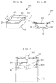
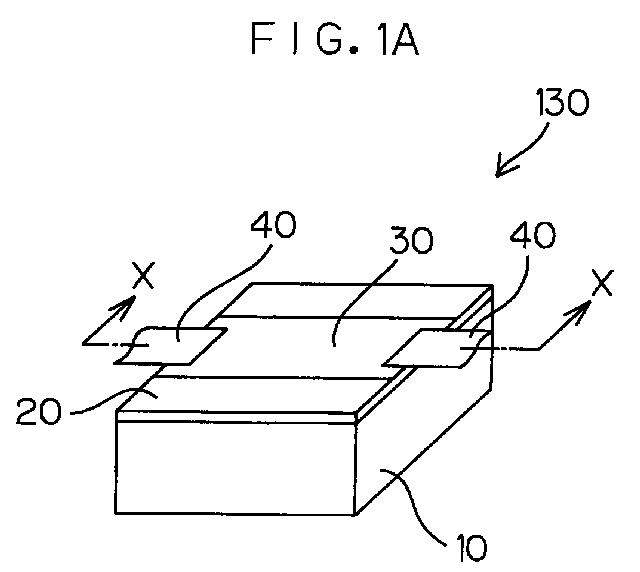
- Figs. 1A and 1B are a perspective view and a sectional view, respectively, which illustrate a safety device according to one embodiment of the present invention.
- the safety device 130 includes a container 10 having a recess formed in the center thereof and a thin plate 20 as a cover member which sealingly covers the mouth of the container 10.
- the thin plate 20 is composed of a brittle material and adapted to be ruptured when a difference between pressures exerted on opposite sides of the thin plate 20 exceeds a predetermined level.
- the thin plate 20 is bonded to the container 10, for example, with an adhesive.
- Examples of specific brittle materials include ceramic materials, glass materials and glass ceramic materials.
- the container 10 is not necessarily required to be composed of a ceramic material, but preferably composed of the same material as the thin plate 20 for stable attachment of the thin plate 20 to the container 10. Where the thin plate 20 and the container 10 are composed of the same ceramic material, it is also possible to fix the thin plate 20 to the container 10 in a ceramic sintering process.
- a sealed reference pressure chamber 50 is formed by covering the recess 10a of the container 10 with the thin plate 20.
- one surface of the thin plate 20 is present in the reference pressure chamber 50 so as to be subjected to the inside pressure (e.g., atmospheric pressure) of the reference pressure chamber 50.
- a conductive path 30 is formed on the other surface of the thin plate 20 not facing to the reference pressure chamber 50 by a thick film printing technique. Electrodes 40, 40 are brazed to opposite edges of the thin plate 20.
- Fig. 2 illustrates a secondary battery in which the safety device 130 shown in Figs. 1A and 1B is incorporated.
- a casing 110 is filled with an electrolytic solution 70, in which a positive electrode 90 and a negative electrode 100 as internal electrodes are immersed with a separator 80 interposed therebetween.
- the positive electrode 90 and the negative electrode 100 are actually of a plural-layer structure with the separator 80 interposed therebetween, these electrodes are schematically illustrated in Fig. 2.
- the positive electrode 90 is connected via the safety device 130 to an output portion 120 as an external electrode led out of the casing 110.
- the negative electrode 100 is electrically connected to the casing 110 via an interconnection not shown.
- the safety device 130 is provided between the output portion 120 and the positive electrode 90 in the electrolytic solution 70 within the casing 110.
- the electrodes 40, 40 connected to opposite ends of the conductive path 30 formed on the thin plate 20 of the safety device 130 are respectively connected to the output portion 120 and the positive electrode 90.
- the safety device 130 is connected to the positive electrode 90, but may be connected to the negative electrode 100.
- the secondary battery of such a construction If the secondary battery of such a construction is overcharged for some reason, a gas evolves inside the battery, thereby increasing the inside pressure.
- the battery inside pressure reaches a certain level, the pressure difference between the opposite sides of the thin plate 20 exceeds the predetermined level, so that the thin plate 20 is ruptured.
- the conductive path 30 formed on the thin plate 20 is cut off to interrupt the charging process. The interruption of the charging process ceases the evolution of the gas inside the battery, thereby preventing further pressure increase.
- the thin plate 20, which is composed of the brittle material, is assuredly ruptured without elastic deformation thereby to cut off the conductive path 30 when the pressure difference between the opposite sides thereof reaches the predetermined level.
- the thickness and material of the thin plate 20 may properly be determined or selected depending on the inside pressure level at which the conductive path is to be cut off and the allowable size of the safety device 130.
- the following is a specific example of the safety device 130 shown in Figs. 1A and 1B.
- the container 10 herein employed was a 5-mm square and 3-mm thick rectangular container having a 4-mm square and 2-mm deep recess therein.
- the thin plate 20 had a thickness of 0.1mm.
- the container 10 and the thin plate 20 were each formed of an alumina-based ceramic material.
- the conductive path 30 was formed of Cu by the thick film printing method.
- the thin plate 20 was sealingly bonded to the container 10 with an epoxy adhesive, and a cavity defined therein was at a normal pressure.
- the container and the cavity each had a rectangular configuration in this specific example, but may have any other configurations, as long as the thin plate is so dimensioned as to be ruptured at a required pressure level.
- Fig. 3 is a sectional view illustrating the construction of a safety device 131 according to a second embodiment of the present invention.
- the safety device 131 can be used instead of the safety device 130 in the secondary battery shown in Fig. 2.
- components corresponding those shown in Fig. 1 are denoted by the same reference numerals as in Fig. 1.
- the thin plate 20 having a very small thickness.
- the thin plate 20 is composed of a ceramic material, for example, the thickness thereof is about 0.1mm or smaller.
- Such a thin ceramic plate may be cracked even only by holding it with tweezers and, therefore, is difficult to handle in the fabrication process.
- a cover member 22 which has a thin plate portion 20A and a peripheral greater thickness portion 21 integrally formed with the thin plate portion 20A. More specifically, the safety device 131 is constructed such that a container 10 having a recess 10a in the center thereof is covered with the cover member 22 to define a sealed reference pressure chamber 50 therein.
- the cover member 22 is free from cracking in the fabrication process, because the cover member 22 can be handled by holding the greater thickness portion 21 thereof.
- the pressure difference between opposite sides of the thin plate portion 20A of the cover member 22 the thin plate portion 20A is assuredly ruptured.
- the safety device 131 is highly reliable as in the first embodiment.
- Fig. 4 is a perspective view illustrating the construction of a safety device 132 according to a third embodiment of the present invention.
- the safety device 132 can be employed instead of the safety device 130 in the secondary battery shown in Fig. 2.
- components corresponding those shown in Fig. 1 are denoted by the same reference numerals as in Fig. 1.
- the safety device 132 is constructed such that the mouth of a container 10 having a recess 10a is covered with a substrate 24 which has a greater thickness than the thin plate 20 to define a reference pressure chamber 50 therein.
- a groove having a flat bottom face is provided in a surface of the substrate 24 opposite from the reference pressure chamber 50, and a portion of the substrate 24 under the groove serves as a thin plate portion 20B.
- the thickness of the thin plate portion 20B can accurately be set by properly selecting a working method.
- the thin plate portion 20B is adapted to be ruptured when a pressure difference between opposite sides thereof reaches a predetermined level.
- a conductive path 30 is formed on a surface of the thin plate portion 20B facing to the reference pressure chamber (or opposite from the groove 23), and adapted to be cut off when the thin plate portion 20B is ruptured.
- the substrate 24 has a rectangular configuration of a size slightly greater than the container 10 as viewed in plan.
- the electrodes 40, 40 are brazed to the conductive path 30 on portions of the substrate 24 projecting outside the container 10.
- Figs. 5A, 5B and 5C are diagrams schematically illustrating a fabrication process for the safety device 132 of this embodiment.
- a substrate 60 having split grooves 61 formed in one surface thereof is prepared which is to be split along the grooves 61 into a plurality of substrate pieces.
- the thickness of the substrate 60 is greater than the thickness of the thin plate portion 20B which is adapted to be ruptured for cut-off of the conductive path 30.
- a plurality of conductive paths 30 for a plurality of safety devices 132 are formed on the substrate 60 by a printing process or the like (Fig. 5A).
- the substrate 60 is turned over, and a plurality of grooves 23 are formed on the other surface of the substrate 60 as extending perpendicularly to the conductive paths 30 by a laser machining process or a sand-blast process for formation of thin plate portions 20B (Fig. 5B).
- the substrate 60 is turned over again, and a plurality of containers 10 each having a recess 10a in the center thereof are bonded onto the surface of the substrate 60 formed with the conductive paths 30 with an adhesive or the like (Fig. 5C). Thereafter, the substrate 60 is split along the split grooves 61 to provide the plurality of safety devices 132 each having the construction shown in Fig. 4.
- the printing process for the formation of the conductive paths 30 and the groove forming process for formation of the thin plate portions 20B can be performed in a batch for fabrication of the plurality of safety devices 132. Therefore, the safety devices 132 can efficiently be mass-produced.
- the electrode attaching step can also easily be adapted for the mass production.
- the substrate 60 shown in Fig. 5C is split into a plurality of elongate substrate strips extending along the conductive paths 30 in the substrate splitting process, and the electrodes 40 are attached to the conductive paths of each of the elongate substrate strips for plural safety devices. Then, the electrodes 40 and the substrate strips are further split. Accordingly, there is no need to handle the electrodes 40 on a one-by-one basis, thereby facilitating the fabrication process.
- the brazing process can effectively be performed, since the plurality of electrodes 40 can be brazed to the conductive paths at a time.
- a 0.3-mm thick alumina-based ceramic plate which was formed with split slits and relatively easy to handle was employed as the splittable substrate 60.
- Conductive portions 30 for a plurality of safety devices 132 were formed of Cu on one surface of the substrate 60 by a thick film printing process.
- Grooves 23 each having a width of about 1mm and a depth of 0.25mm were formed on the other surface of the substrate 60 as extending perpendicularly to the conductive portions 30 by a laser machining process.
- containers 10 separately prepared were bonded onto the surface of the substrate 60 not formed with the grooves 23 with an epoxy adhesive. Then, the substrate 60 was split along the split slits for provision of the individual devices. This fabrication process allowed for easy mass production of the very small size devices.
- Fig. 6A is a partially broken perspective view illustrating a safety device 133 of a fourth embodiment of the present invention.
- a spacer plate 7 is provided integrally with a thin plate 5 on one surface thereof.
- the thin plate 5 is composed of a brittle material such as a ceramic material, a glass material or a glass ceramic material.
- the spacer plate 7 is a hollow cylindrical member which has a hollow central portion serving as a reference pressure chamber 6 and is connected to the peripheral edge of the thin plate 5.
- a cover plate 9 is provided integrally with the spacer plate 7 on a side thereof opposite from the thin plate 5 as covering the reference pressure chamber 6.
- the cover plate 9 is formed with a through-hole 9a, which is closed with a filler 8.
- a conductive path 10 is formed on the other surface (exposed surface) of the thin plate 5 by a vapor deposition process.
- the safety device 133 can be employed instead of the safety device 130 in the secondary battery shown in Fig. 2.
- a greater pressure is exerted on the surface of the thin plate 5 opposite from the reference pressure chamber 6 due to overcharging or the like so that a pressure difference between the opposite sides of the thin plate 5 reaches an abnormal level greater than a predetermined level, the thin plate 5 is ruptured to cut off the conductive path 10 for interruption of the charging of the secondary battery from a main power source. Since the thin plate 5 is formed of a brittle material such as a ceramic material, a glass material or a glass ceramic material, the thin plate 5 can assuredly be ruptured without elastic deformation to cut off the conductive path 10.
- a juncture between the spacer plate 7 and the thin plate 5 has a corner A (inner corner facing to the reference pressure chamber 6) having a curvature radius R of not greater than 0.1mm, so that the thin plate 5 can assuredly be ruptured at an abnormal pressure.
- a curvature radius R of not greater than 0.1mm
- the juncture corner is not a round corner but a flat face corner as indicated in Fig. 6C
- the breadth C of a flat face is herein defined as the curvature radius. Such definition is applied to any other configuration of the juncture corner.
- the safety device 133 is fabricated by stacking green sheets one on another, so that the curvature radius R of the juncture corner A can be made not greater than 0.1mm.
- the reference pressure chamber 6 preferably has such a plan configuration that the major- to minor-axis length ratio thereof is in a range between 1.0 and 1.2.
- the conductive path 10 can instantaneously and completely be cut off when abnormal pressure occurs.
- the terms "major axis length” and “minor axis length” herein mean the greatest diameter and the smallest diameter, respectively, of the reference pressure chamber 6 as viewed in plan.
- the major axis length and the minor axis length are regarded as corresponding to the length of the diagonal thereof and the length of the side thereof, respectively. In such a case, the major- to minor-axis length ratio is about 1.4 and, hence, falls out of the preferred scope.
- the material for the thin plate 5 to be ruptured has a Young's modulus of not lower than 60GPa and a flexural strength of 70 to 1000MPa, and the thickness of the thin plate 5 is 10 to 100 ⁇ m.
- the spacer plate 7 and the cover plate 9 are preferably composed of the same material as the thin plate 5.
- a slurry is prepared by blending a powdery ceramic material such as alumina or zirconia, a powdery glass material or a powdery glass ceramic material with an organic binder, an plasticizer and a solvent.
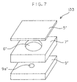
- a thin green sheet 5' for preparation of the thin plate 5, a thick green sheet 7' for preparation of the spacer plate 7 and a green sheet 9' for preparation of the cover plate 9 as shown in Fig. 7 are formed from the resulting slurry by a doctor blade method, a calender roll method, a rolling method or a press method.
- a water-soluble slurry may be employed, instead of the solvent-based slurry, which is prepared by blending a powdery ceramic material with an organic binder, a plasticizer, a dispersant and deionized water.
- the thick sheet may otherwise be prepared by combining a plurality of thin green sheets into a laminate.
- the thick green sheet 7' is formed with a through-hole 6' which will later serve as the reference pressure chamber 6 and the green sheet 9' is formed with a minute through-hole 9a' by a stamping process using a metal stamping die.
- the thin green sheet 5', the thick green sheet 7' having the through-hole 6' and the thick green sheet 9' having the minute through-hole 9a' are stacked one on another to be combined into a laminate and, after a while, the resulting laminate is integrally sintered at a temperature of not lower than 800 C in an atmospheric environment.
- the spacer plate 7 and the cover plate 9 are thus integrally sintered, the conducive path 10 is formed on the thin plate 5. Then, the through-hole 9a extending to the reference pressure chamber 6 is closed with a filler 8 such as of a resin. Thus, the safety device 133 of the present embodiement is obtained.
- the through-hole 9a which is finally closed with the filler 8 serves to keep the reference pressure chamber 6 at an atmospheric pressure for prevention of breakage of the laminate during the fabrication process.
- a powdery ceramic material such as alumina or zirconia, a glass material or a glass ceramic material is mixed with a binder, and green sheets for the spacer plate 7 and the thin plate 5 are formed from the resulting mixture by a press method.
- the sheets are stacked one on the other to be combined into a laminate, and integrally sintered at a temperature of not lower than 800 C in an atmospheric environment.
- the reference pressure chamber 6 is covered with the cover plate 9 and, after the thin plate 5 is processed to a desired thickness, the conductive path 10 is formed on the thin plate 5.
- the conductive path 10 is formed of a metal such as Cu, Ni, Al, Au, Ag or Pd or an alloy thereof by a plating method, a sputtering method, a vapor deposition method or a printing method.
- the safety device 133 has a very small size, so that a multiplicity of such safety devices can be produced at a time by a multi-production method.
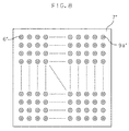
- a multiplicity of through-holes 6' are formed in a single green sheet 7', which is then combined into a laminate with a green sheet 9' formed with a multiplicity of through-holes 9a' and a thin green sheet 5'. Then, the laminate is sintered. After formation of conduction paths 10, the resulting product is cut.
- the multiplicity of safety devices 133 are produced at a time.
- the curvature radius R of the corner A of the juncture between the thin plate 5 and the spacer plate 7 can be reduced to not greater than 0.1mm by integrally sintering at least the green sheets for the thin plate 5 and the spacer plate 7 combined into a laminate. This allows for assured rupture of the thin plate 5 under an abnormal pressure.
- the safety device of this embodiment is constructed such that the cover plate 9 is proviced on one side of the thin plate 5 to define the sealed reference pressure chamber 6, the safety device may include only the thin plate 5 and the spacer plate 7 and be designed so that the thin plate 5 is ruptured by a pressure difference between the opposite sides of the thin plate 5 in another embodiment.
- the alumina power was blended with an acrylic-ester-based binder, a plasticizer of hexylene glycol, a dispersant and deionized water for preparation of a water-soluble slurry.
- a thin alumina green sheet and thick alumina green sheets were prepared from the slurry by the calender roll method.
- the thick sheets were respectively stamped out with metal dies for formation of a through-hole 6' which will later serve as the reference pressure chamber 6 and a minute through-hole 9a' in the respective sheets.
- the metal dies herein used were configured so as to allow the through-holes 6' and 9' to have desired shapes after the sintering.
- the metal die for the stamping of the minute through-hole 9a' has a diameter of 0.3mm.
- the thin green sheet 5', the green sheet 7' having the through-hole 6' and the green sheet 9' having the minute through-hole 9a' were stacked one on another as shown in Fig. 7 to be combined into a laminate.
- the resulting laminate was thermocompress-bonded at 60 C and 50kgf/cm 2 , and then sintered at 1570 C in an atmospheric environment.
- the safety device 133 was obtained.
- safety device samples were each fabricated by integrally press-molding a spacer plate portion and a thin plate portion with a mold by a known press molding method and then subjecting the thin plate portion to a thickness adjustment process.
- the molds used herein were designed so as to have different corner configurations which each corresponded to an inner corner of the juncture between the spacer plate portion and the thin plate portion.
- safety device samples which had inner corners having different curvature radii R within a range between 0.01 to 0.20mm at the juncture between the spacer plate 7 and the thin plate 5 were fabricated, and a relationship between the curvature radius of the juncture corner and the thin plate rupture ratio was examined.
- the thin plates 5 of the safety device smaples each had a thickness of 50 ⁇ m.
- the thin plate rupture ratio was determined in the following manner.
- the fabricated safety device samples were put in a pressure vessel, and the inside pressure of the vessel was gradually increased.
- the rupture ratio was calculated on the basis of the number of safety device samples in which the thin plate was ruptured until the pressure reached a maximum pressure of 7kg/cm 2 .
- the maximum pressure was set to a level corresponding to an inside pressure level of a secondary battery which was considered to be abnormal.
- the safety device samples A-4, A-5 in which the curvature radius R of the corner of the juncture between the spacer plate 7 and the thin plate 5 was greater than 0.1mm were fabricated by the press molding method, and had lower levels of rupture ratio, i.e., not higher than 60%.
- the other safety device samples which were fabricated by the green sheet stacking method each had a curvature radius R of not greater than 0.1mm with a higher rupture ratio, i.e., not lower than 70%.
- the curvature radius of the juncture corner of the safety device should be 0.1mm or smaller, preferably as small as possible. It is also understood that the safety device fabrication process using green sheets is more advantageous.
- a major- to minor-axis length ratio of not higher than 1.2 (samples A-1 to A-3, B-1, B-2, and D-1 to D-2) provided for a rupture ratio of 100%. Even where the reference pressure chamber had any other configuration, the rupture ratio was not influenced by the configuration, as long as the major- to minor-axis length ratio of the juncture corner is within the aforesaid range.
- Safety device samples having substantially the same construction as the safety device 133 were each fabricated in substantially the same manner as described above by stacking green sheets composed of a powdery ceramic material (alumina or zirconia), a glass material or a glass ceramic material as shown by A to F in Table 3.
- the sintering temperature was properly selected depending on the type of the material.
- Material Characteristics of material Young's modulus(GPa) Flexural strength(MPa) A Alumina 325 300 B Zirconia 180 1000 C Zirconia 200 1500 D Glass ceramic 100 200 E Glass 58 70 F Crystallized Glass 100 240
- the safety device samples were each constructed such that: the thin plate 5 thereof had a thickness of 8 to 150 ⁇ m; the reference pressure chamber 6 was of a circular configuration having a diameter of 3mm and a major- to minor-axis length ratio of 1.0; and the through-hole 9a communicating with the reference pressure chamber 6 had a diameter of 0.3mm and was closed with a resin.
- the safety device samples thus fabricated were put in a pressure vessel, and the inside pressure of the vessel was gradually increased to a maximum pressure of 7kg/cm 2 for determination of the thin plate rupture ratio.
- the maximum pressure was set to a level corresponding to an inside pressure level of a secondary battery which was considered to be abnormal.
- the material for the thin plate 5 has a Young's modulus of not lower than 60GPa and a flexural strength of 80 to 1000MPa. This is applicable to the thin plate 20 and the thin plate portions 20A and 20B according to the first to third embodiments.
- the thin plate 5 had a thickness of smaller than 10 ⁇ m
- the thin plate was liable to have minute defects therein because of its smaller thickness. Accordingly, there was air communication between the inside and outside of the reference pressure chamber 6, making it impossible to rupture the thin plate 5 or resulting in a lower rupture ratio.
- a greater thickness of the thin plate resulted in a lower rupture rate because a higher pressure was required for the rupture of the thin plate.
- the thickness of the thin plate 5 is 10 to 100 ⁇ m. This is applicable to the thin plate 20 of the first embodiment. It is more preferred that the thickness of the thin plate 5 for the safety device is 25 to 75 ⁇ m. This is applicable to the thin plate 20 and the thin plate portions 20A and 20B according to the first to third embodiments.
- the thin plates 20, 5 and the substrate 60 may be composed of any brittle material selected from ceramic materials such as alumina-, zirconia- and titania-based ceramic materials, forsterite, steatite and cordierite, various glass materials, and glass-ceramic composite materials.
- the conductive paths 30, 10 may be composed of any metal selected from Cu, Ni, Al, Au, Ag and stainless steel or an alloy of any of these metals.
- a single safety device is incorporated in the casing of the secondary battery in the embodiments described above, two or more safety devices may be connected in series and interposed between the internal and external electrodes. In such a case, effectuation of any of these safety devices interrupts the charging process of the battery. Thus, the reliability of the secondary battery can further be improved.
- the safety device of the present invention can be used as an explosion-preventive safety device for preventing an explosion due to pressure buildup for use not only in the secondary battery but also in any of various apparatuses such as air compressors. That is, the safety device of the present invention is applicable to various pressure-responsive safety devices which can be effectuated at a desired pressure level by properly selecting the thickness of the thin plate.
Landscapes
- Chemical & Material Sciences (AREA)
- Chemical Kinetics & Catalysis (AREA)
- Electrochemistry (AREA)
- General Chemical & Material Sciences (AREA)
- Physics & Mathematics (AREA)
- General Physics & Mathematics (AREA)
- Fluid Mechanics (AREA)
- Connection Of Batteries Or Terminals (AREA)
- Gas Exhaust Devices For Batteries (AREA)
Abstract
Description
- The present invention relates to a safety device for maintaining the safety of an apparatus by cutting off a current flow path in response to pressure buildup inside the apparatus. Particularly, the invention relates to a safety device for use in smaller size apparatuses such as rechargeable secondary batteries, typically lithium ion batteries, with an imperative need for size reduction. Further, the invention relates to a secondary battery using such a safety device.
- With the spread of portable information systems such as portable phones, video cameras and notebook personal computers, high performance rechargeable secondary batteries such as lithium ion batteries have come into widespread use.
- Fig. 9 is a schematic diagram illustrating the basic construction of a conventional lithium ion battery. The lithium ion battery has such a simple construction that a
positive electrode 90 and anegative electrode 100 are disposed in anelectrolytic solution 70 of an organic solvent with aseparator 80 interposed therebetween. Migration of Li ions between thepositive electrode 90 and thenegative electrode 100 causes the battery to be charged and discharged. Lithium oxide is employed for thepositive electrode 90, and a carbon compound is employed for thenegative electrode 100. - The secondary battery offers high performance. However, when the battery is overcharged or short-circuited, a gas evolves due to decomposition of the electrolytic solution thereby to increase the inside pressure of the battery. In the worst case, this results in explosion of the battery. Therefore, batteries of this type are provided with various types of safety devices.
- The safety devices are generally classified into two types, i.e., safety valve mechanisms and current flow interruption mechanisms. The safety valve mechanisms are designed such that a safety valve provided in a battery surface is opened by buildup of the battery inside pressure thereby to release the inside gas for prevention of further increase in the inside pressure. On the other hand, the current flow interruption mechanisms are adapted to cut off a conductive path by utilizing the buildup of the inside gas pressure or to cut off a conductive path in response to detection of a temperature rise caused by the pressure build-up inside the battery.
- As a current flow interruption mechanism responsive to a temperature rise, a simple mechanism employing a positive temperature coefficient (PTC) element as a thermosensitive element has been put to practical use. However, there is a time lag between the buildup of the battery inside pressure and the temperature rise. Therefore, such a mechanism fails to ensure a stable operation, making it difficult to provide a highly reliable safety device.
- A current flow interruption mechanism responsive to the buildup of the gas pressure inside a battery is disclosed, for example, in Japanese Unexamined Patent Publication (KOKAI) No. 9-55197 (1997). In accordance with this art, the mechanism includes a pressure-responsive displacement member adapted to be displaced by the increase in the battery inside pressure, and is designed so that a conductive path is cut off by the displacement of the pressure-responsive displacement member.
- In this art, the conductive path, the pressure-responsive displacement member and a support member for supporting these components are required. Therefore, the mechanism has a complicated construction, presenting problems associated with the size reduction and cost reduction.
- In recent years, the portable information systems have remarkably been downsized, and further size reduction thereof will inevitably be in demand. Therefore, the size reduction of the batteries to be incorporated in such portable information systems is imperative. Since a safety device including any of the aforesaid complicated mechanisms of the prior art has a relatively large size, it is very difficult to embody a smaller size battery with such a safety device.
- It is a first object of the present invention to provide a safety device which has an easily downsizable construction.
- It is a second object of the present invention to provide a safety device which can readily be incorporated in a battery.
- It is a third object of the present invention to provide a highly reliable secondary battery provided with a safety device.
- It is a fourth object of the present invention to provide an advantageous fabrication method for a highly reliable safety device.
- The safety device according to the present invention includes a thin plate of a brittle material adapted to be ruptured by a difference between pressures exerted on opposite sides thereof, and a conductive path provided on the thin plate and adapted to be cut off by the rupture of the thin plate.
- The thin plate may be provided integrally with a peripheral greater thickness portion.
- One surface of the thin plate is preferably present in a reference pressure chamber. In this case, when a greater (or smaller) pressure is exerted on the other surface of the thin plate, the thin plate is ruptured, thereby cutting off the conductive path. Thus, the safety device is of a pressure-responsive type which is effectuated when the pressure is out of a predetermined allowable range.
- More specifically, the safety device of the pressure-responsive type is preferably embodied such that the reference pressure chamber is defined by a partition wall partly constituted by the thin plate. In this case, the reference pressure chamber is preferably sealed.
- The safety device may otherwise be constructed such that the reference pressure chamber is defined by a plate member having a cavity and a cover member which covers the cavity, and the cover member or a bottom of the cavity is comprised of the thin plate.
- The safety device may otherwise be constructed such that the reference pressure chamber is partly defined by a spacer plate provided integrally with the thin plate on the one surface thereof and having a through-hole through which a portion of the one surface of the thin plate is exposed.
- In this case, a juncture between the spacer plate and the thin plate preferably has an inner corner having a curvature radius of not greater than 0.1mm. Thus, when the pressure difference between the opposite sides of the thin plate reaches a predetermined level, the rupture of the thin plate can instantaneously and assuredly be caused. Hence, the safety device is highly reliable.
- Further, the reference pressure chamber is preferably sealed by a cover plate provided on a side of the spacer plate opposite from the thin plate as covering the spacer plate.
- The reference pressure chamber preferably has a major- to minor-axis length ratio of 1.0 to 1.2 as viewed in plan. This ensures the rupture of the thin plate when the pressure difference between the opposite sides thereof reaches the predetermined level.
- The brittle material may be selected from the group consisting of ceramic materials, glass materials and glass ceramic materials.
- The brittle material preferably has a Young's modulus of not lower than 60GPa and a flexural strength of 80 to 1000MPa.
- The thin plate preferably has a thickness of 10 to 100µm. Thus, the thin plate is easy to handle in production thereof, and has stable rupture characteristics.
- For more stable rupture characteristics of the thin plate, the thin plate preferably has a thickness of 25 to 75µm.
- The secondary battery according to the present invention includes the aforesaid safety device which is interposed between an internal electrode and an external electrode in a battery casing.
- Since the safety device has a small and simple construction, it is easy to incorporate the safety device in the battery. Thus, the secondary battery with the safety device is highly reliable with a smaller size.
- The thin plate, if composed of a ceramic material, is virtually free from time-related changes, so that operational variations of the safety device can be suppressed for an extended period without provision of a special protective film on the thin plate.
- The fabrication method for the safety device according to the present invention includes the steps of: forming a green sheet for a thin plate from a brittle material; forming a green sheet for a spacer plate having a hole which later serves as a reference pressure chamber; and combining the thin plate green sheet with the spacer plate green sheet into a laminate and integrally sintering the laminate.
- In accordance with the present invention, the curvature radius of a corner of a juncture between the thin plate and the spacer plate can be reduced, and the safety device can be fabricated at lower costs.
- In accordance with one embodiment of the present invention, the fabrication method further includes the step of forming a green sheet for a cover plate. In the combining and sintering step, the spacer plate green sheet is combined with the thin plate green sheet and the cover plate green sheet as being held therebetween and the three combined sheets are integrally sintered.
- The fabrication method preferably further includes the steps of forming a through-hole in a portion of the cover plate which opposes to the reference pressure chamber and, after the sintering step, closing the through-hole.
- By way of example only, specific embodiments of the present invention will now be described, with reference to the accompanying drawings, in which:-
- Fig. 1A is a perspective view illustrating the construction of a safety device according to a first embodiment of the present invention, and Fig. 1B is a sectional view taken along a line X-X in Fig. 1A;
- Fig. 2 is a partially broken side view schematically illustrating the construction of a secondary battery which employs the safety device of the present invention;
- Fig. 3 is a sectional view illustrating the construction of a safety device according to a second embodiment of the present invention;
- Fig. 4 is a perspective view illustrating the construction of a safety device according to a third embodiment of the present invention;
- Figs. 5A, 5B and 5C are diagrams illustrating a fabrication process for the safety device of the third embodiment;
- Fig. 6A is a partially broken perspective view illustrating a safety device according to a fourth embodiment of the present invention, and Figs. 6B and 6C are sectional views illustrating a portion of the safety device indicated at A in Fig. 6A;
- Fig. 7 is a perspective view for explaining a fabrication method for the safety device of the fourth embodiment;
- Fig. 8 is a plan view of green sheets to be employed in the fabrication of the safety device of the fourth embodiment; and
- Fig. 9 is a schematic diagram illustrating the construction of a typical lithium ion battery.
-
- Figs. 1A and 1B are a perspective view and a sectional view, respectively, which illustrate a safety device according to one embodiment of the present invention. The
safety device 130 includes acontainer 10 having a recess formed in the center thereof and athin plate 20 as a cover member which sealingly covers the mouth of thecontainer 10. Thethin plate 20 is composed of a brittle material and adapted to be ruptured when a difference between pressures exerted on opposite sides of thethin plate 20 exceeds a predetermined level. Thethin plate 20 is bonded to thecontainer 10, for example, with an adhesive. - Examples of specific brittle materials include ceramic materials, glass materials and glass ceramic materials.
- The
container 10 is not necessarily required to be composed of a ceramic material, but preferably composed of the same material as thethin plate 20 for stable attachment of thethin plate 20 to thecontainer 10. Where thethin plate 20 and thecontainer 10 are composed of the same ceramic material, it is also possible to fix thethin plate 20 to thecontainer 10 in a ceramic sintering process. - In the
safety device 130, a sealedreference pressure chamber 50 is formed by covering therecess 10a of thecontainer 10 with thethin plate 20. Thus, one surface of thethin plate 20 is present in thereference pressure chamber 50 so as to be subjected to the inside pressure (e.g., atmospheric pressure) of thereference pressure chamber 50. Aconductive path 30 is formed on the other surface of thethin plate 20 not facing to thereference pressure chamber 50 by a thick film printing technique.Electrodes thin plate 20. - Fig. 2 illustrates a secondary battery in which the
safety device 130 shown in Figs. 1A and 1B is incorporated. Acasing 110 is filled with anelectrolytic solution 70, in which apositive electrode 90 and anegative electrode 100 as internal electrodes are immersed with aseparator 80 interposed therebetween. Although thepositive electrode 90 and thenegative electrode 100 are actually of a plural-layer structure with theseparator 80 interposed therebetween, these electrodes are schematically illustrated in Fig. 2. - The
positive electrode 90 is connected via thesafety device 130 to anoutput portion 120 as an external electrode led out of thecasing 110. Thenegative electrode 100 is electrically connected to thecasing 110 via an interconnection not shown. - The
safety device 130 is provided between theoutput portion 120 and thepositive electrode 90 in theelectrolytic solution 70 within thecasing 110. Theelectrodes conductive path 30 formed on thethin plate 20 of thesafety device 130 are respectively connected to theoutput portion 120 and thepositive electrode 90. - In the embodiment shown in Fig. 2, the
safety device 130 is connected to thepositive electrode 90, but may be connected to thenegative electrode 100. - If the secondary battery of such a construction is overcharged for some reason, a gas evolves inside the battery, thereby increasing the inside pressure. When the battery inside pressure reaches a certain level, the pressure difference between the opposite sides of the
thin plate 20 exceeds the predetermined level, so that thethin plate 20 is ruptured. Thus, theconductive path 30 formed on thethin plate 20 is cut off to interrupt the charging process. The interruption of the charging process ceases the evolution of the gas inside the battery, thereby preventing further pressure increase. - The
thin plate 20, which is composed of the brittle material, is assuredly ruptured without elastic deformation thereby to cut off theconductive path 30 when the pressure difference between the opposite sides thereof reaches the predetermined level. - The thickness and material of the
thin plate 20 may properly be determined or selected depending on the inside pressure level at which the conductive path is to be cut off and the allowable size of thesafety device 130. - The following is a specific example of the
safety device 130 shown in Figs. 1A and 1B. - The
container 10 herein employed was a 5-mm square and 3-mm thick rectangular container having a 4-mm square and 2-mm deep recess therein. Thethin plate 20 had a thickness of 0.1mm. Thecontainer 10 and thethin plate 20 were each formed of an alumina-based ceramic material. Theconductive path 30 was formed of Cu by the thick film printing method. - The
thin plate 20 was sealingly bonded to thecontainer 10 with an epoxy adhesive, and a cavity defined therein was at a normal pressure. - For a rupture test, 100 safety devices each having such a construction were prepared. An air pressure was externally applied to each of the safety devices, and rupture conditions of the
thin plate 20 were recorded when thethin plate 20 was ruptured. The test results are shown in Table 1. The safety devices were all ruptured in a pressure range between 6 and 8kg/cm2, which satisfied a required rupture pressure level. Further, it was confirmed that theconductive path 30 was assuredly cut off in each of the safety devices.External pressure(kg/cm2) -6 6-6.5 6.5-7 7-7.5 7.5-8 8- Number of ruptured devices 0 8 31 50 11 0 - The container and the cavity each had a rectangular configuration in this specific example, but may have any other configurations, as long as the thin plate is so dimensioned as to be ruptured at a required pressure level.
- Fig. 3 is a sectional view illustrating the construction of a
safety device 131 according to a second embodiment of the present invention. Thesafety device 131 can be used instead of thesafety device 130 in the secondary battery shown in Fig. 2. In Fig. 3, components corresponding those shown in Fig. 1 are denoted by the same reference numerals as in Fig. 1. - In the fabrication of the
safety device 130 according to the first embodiment, it is necessary to handle thethin plate 20 having a very small thickness. Where thethin plate 20 is composed of a ceramic material, for example, the thickness thereof is about 0.1mm or smaller. Such a thin ceramic plate may be cracked even only by holding it with tweezers and, therefore, is difficult to handle in the fabrication process. - In the case of the
safety device 131 shown in Fig. 3, acover member 22 is employed which has athin plate portion 20A and a peripheralgreater thickness portion 21 integrally formed with thethin plate portion 20A. More specifically, thesafety device 131 is constructed such that acontainer 10 having arecess 10a in the center thereof is covered with thecover member 22 to define a sealedreference pressure chamber 50 therein. - With this arrangement, the
cover member 22 is free from cracking in the fabrication process, because thecover member 22 can be handled by holding thegreater thickness portion 21 thereof. When the pressure difference between opposite sides of thethin plate portion 20A of thecover member 22, thethin plate portion 20A is assuredly ruptured. Thus, thesafety device 131 is highly reliable as in the first embodiment. - Fig. 4 is a perspective view illustrating the construction of a
safety device 132 according to a third embodiment of the present invention. Thesafety device 132 can be employed instead of thesafety device 130 in the secondary battery shown in Fig. 2. In Fig. 4, components corresponding those shown in Fig. 1 are denoted by the same reference numerals as in Fig. 1. - In this embodiment, the
safety device 132 is constructed such that the mouth of acontainer 10 having arecess 10a is covered with asubstrate 24 which has a greater thickness than thethin plate 20 to define areference pressure chamber 50 therein. A groove having a flat bottom face is provided in a surface of thesubstrate 24 opposite from thereference pressure chamber 50, and a portion of thesubstrate 24 under the groove serves as athin plate portion 20B. The thickness of thethin plate portion 20B can accurately be set by properly selecting a working method. Thethin plate portion 20B is adapted to be ruptured when a pressure difference between opposite sides thereof reaches a predetermined level. - A
conductive path 30 is formed on a surface of thethin plate portion 20B facing to the reference pressure chamber (or opposite from the groove 23), and adapted to be cut off when thethin plate portion 20B is ruptured. Thesubstrate 24 has a rectangular configuration of a size slightly greater than thecontainer 10 as viewed in plan. Theelectrodes conductive path 30 on portions of thesubstrate 24 projecting outside thecontainer 10. - Figs. 5A, 5B and 5C are diagrams schematically illustrating a fabrication process for the
safety device 132 of this embodiment. First, asubstrate 60 having splitgrooves 61 formed in one surface thereof is prepared which is to be split along thegrooves 61 into a plurality of substrate pieces. The thickness of thesubstrate 60 is greater than the thickness of thethin plate portion 20B which is adapted to be ruptured for cut-off of theconductive path 30. A plurality ofconductive paths 30 for a plurality ofsafety devices 132 are formed on thesubstrate 60 by a printing process or the like (Fig. 5A). In turn, thesubstrate 60 is turned over, and a plurality ofgrooves 23 are formed on the other surface of thesubstrate 60 as extending perpendicularly to theconductive paths 30 by a laser machining process or a sand-blast process for formation ofthin plate portions 20B (Fig. 5B). Thesubstrate 60 is turned over again, and a plurality ofcontainers 10 each having arecess 10a in the center thereof are bonded onto the surface of thesubstrate 60 formed with theconductive paths 30 with an adhesive or the like (Fig. 5C). Thereafter, thesubstrate 60 is split along thesplit grooves 61 to provide the plurality ofsafety devices 132 each having the construction shown in Fig. 4. - In this fabrication process, the printing process for the formation of the
conductive paths 30 and the groove forming process for formation of thethin plate portions 20B can be performed in a batch for fabrication of the plurality ofsafety devices 132. Therefore, thesafety devices 132 can efficiently be mass-produced. - Although the step of attaching the
electrodes 40 to the conductive paths is not shown in Figs. 5A to 5C, the electrode attaching step can also easily be adapted for the mass production. For example, thesubstrate 60 shown in Fig. 5C is split into a plurality of elongate substrate strips extending along theconductive paths 30 in the substrate splitting process, and theelectrodes 40 are attached to the conductive paths of each of the elongate substrate strips for plural safety devices. Then, theelectrodes 40 and the substrate strips are further split. Accordingly, there is no need to handle theelectrodes 40 on a one-by-one basis, thereby facilitating the fabrication process. The brazing process can effectively be performed, since the plurality ofelectrodes 40 can be brazed to the conductive paths at a time. - The following is a specific example of the fabrication process for the
safety device 132 shown in Figs. 5A to 5C. - A 0.3-mm thick alumina-based ceramic plate which was formed with split slits and relatively easy to handle was employed as the
splittable substrate 60.Conductive portions 30 for a plurality ofsafety devices 132 were formed of Cu on one surface of thesubstrate 60 by a thick film printing process.Grooves 23 each having a width of about 1mm and a depth of 0.25mm were formed on the other surface of thesubstrate 60 as extending perpendicularly to theconductive portions 30 by a laser machining process. Thereafter,containers 10 separately prepared were bonded onto the surface of thesubstrate 60 not formed with thegrooves 23 with an epoxy adhesive. Then, thesubstrate 60 was split along the split slits for provision of the individual devices. This fabrication process allowed for easy mass production of the very small size devices. - Fig. 6A is a partially broken perspective view illustrating a
safety device 133 of a fourth embodiment of the present invention. A spacer plate 7 is provided integrally with athin plate 5 on one surface thereof. Thethin plate 5 is composed of a brittle material such as a ceramic material, a glass material or a glass ceramic material. The spacer plate 7 is a hollow cylindrical member which has a hollow central portion serving as areference pressure chamber 6 and is connected to the peripheral edge of thethin plate 5. Acover plate 9 is provided integrally with the spacer plate 7 on a side thereof opposite from thethin plate 5 as covering thereference pressure chamber 6. Thecover plate 9 is formed with a through-hole 9a, which is closed with afiller 8. Aconductive path 10 is formed on the other surface (exposed surface) of thethin plate 5 by a vapor deposition process. - The
safety device 133 can be employed instead of thesafety device 130 in the secondary battery shown in Fig. 2. When a greater pressure is exerted on the surface of thethin plate 5 opposite from thereference pressure chamber 6 due to overcharging or the like so that a pressure difference between the opposite sides of thethin plate 5 reaches an abnormal level greater than a predetermined level, thethin plate 5 is ruptured to cut off theconductive path 10 for interruption of the charging of the secondary battery from a main power source. Since thethin plate 5 is formed of a brittle material such as a ceramic material, a glass material or a glass ceramic material, thethin plate 5 can assuredly be ruptured without elastic deformation to cut off theconductive path 10. - In this
safety device 133, a juncture between the spacer plate 7 and thethin plate 5 has a corner A (inner corner facing to the reference pressure chamber 6) having a curvature radius R of not greater than 0.1mm, so that thethin plate 5 can assuredly be ruptured at an abnormal pressure. Thus, when an abnormal pressure occurs, cracking of the thin plate starts from the juncture corner A for the assured rupture of thethin plate 5. - Where the juncture corner is not a round corner but a flat face corner as indicated in Fig. 6C, the breadth C of a flat face is herein defined as the curvature radius. Such definition is applied to any other configuration of the juncture corner.
- Where the formation of the
reference pressure chamber 6 is to be achieved by a press forming process or a cutting process in the fabrication process for this safety device, it is impossible to make the curvature radius R of the juncture corner A not greater than 0.1mm, so that the rupture of thethin plate 5 at an abnormal pressure cannot be ensured. In a fabrication method to be described later, thesafety device 133 is fabricated by stacking green sheets one on another, so that the curvature radius R of the juncture corner A can be made not greater than 0.1mm. - In the present invention, the
reference pressure chamber 6 preferably has such a plan configuration that the major- to minor-axis length ratio thereof is in a range between 1.0 and 1.2. Thus, theconductive path 10 can instantaneously and completely be cut off when abnormal pressure occurs. The terms "major axis length" and "minor axis length" herein mean the greatest diameter and the smallest diameter, respectively, of thereference pressure chamber 6 as viewed in plan. Where the reference pressure chamber has a square configuration, the major axis length and the minor axis length are regarded as corresponding to the length of the diagonal thereof and the length of the side thereof, respectively. In such a case, the major- to minor-axis length ratio is about 1.4 and, hence, falls out of the preferred scope. - In the present invention, the material for the
thin plate 5 to be ruptured has a Young's modulus of not lower than 60GPa and a flexural strength of 70 to 1000MPa, and the thickness of thethin plate 5 is 10 to 100µm. Thus, the effectuation pressure of the safety device 33 (at which thethin plate 5 is to be ruptured) is properly adjusted, so that the instantaneous and complete cut-off of theconductive path 10 can be achieved when an abnormal pressure occurs. - Examples of specific materials for the
thin plate 5 include ceramic materials such as alanine and zirconia, glass materials such as crystallized glass materials, and glass ceramic materials. The spacer plate 7 and thecover plate 9 are preferably composed of the same material as thethin plate 5. - Next, an explanation will be given to a fabrication method for the
safety deice 133 of this embodiment. - A slurry is prepared by blending a powdery ceramic material such as alumina or zirconia, a powdery glass material or a powdery glass ceramic material with an organic binder, an plasticizer and a solvent. A thin green sheet 5' for preparation of the
thin plate 5, a thick green sheet 7' for preparation of the spacer plate 7 and a green sheet 9' for preparation of thecover plate 9 as shown in Fig. 7 are formed from the resulting slurry by a doctor blade method, a calender roll method, a rolling method or a press method. - For the formation of the thin and thick green sheets, a water-soluble slurry may be employed, instead of the solvent-based slurry, which is prepared by blending a powdery ceramic material with an organic binder, a plasticizer, a dispersant and deionized water. The thick sheet may otherwise be prepared by combining a plurality of thin green sheets into a laminate.
- The thick green sheet 7' is formed with a through-
hole 6' which will later serve as thereference pressure chamber 6 and the green sheet 9' is formed with a minute through-hole 9a' by a stamping process using a metal stamping die. The thin green sheet 5', the thick green sheet 7' having the through-hole 6' and the thick green sheet 9' having the minute through-hole 9a' are stacked one on another to be combined into a laminate and, after a while, the resulting laminate is integrally sintered at a temperature of not lower than 800 C in an atmospheric environment. - After the
thin plate 5, the spacer plate 7 and thecover plate 9 are thus integrally sintered, theconducive path 10 is formed on thethin plate 5. Then, the through-hole 9a extending to thereference pressure chamber 6 is closed with afiller 8 such as of a resin. Thus, thesafety device 133 of the present embodiement is obtained. - The through-
hole 9a which is finally closed with thefiller 8 serves to keep thereference pressure chamber 6 at an atmospheric pressure for prevention of breakage of the laminate during the fabrication process. - Another fabrication process is as follows. A powdery ceramic material such as alumina or zirconia, a glass material or a glass ceramic material is mixed with a binder, and green sheets for the spacer plate 7 and the
thin plate 5 are formed from the resulting mixture by a press method. The sheets are stacked one on the other to be combined into a laminate, and integrally sintered at a temperature of not lower than 800 C in an atmospheric environment. Then, thereference pressure chamber 6 is covered with thecover plate 9 and, after thethin plate 5 is processed to a desired thickness, theconductive path 10 is formed on thethin plate 5. - The
conductive path 10 is formed of a metal such as Cu, Ni, Al, Au, Ag or Pd or an alloy thereof by a plating method, a sputtering method, a vapor deposition method or a printing method. - The
safety device 133 has a very small size, so that a multiplicity of such safety devices can be produced at a time by a multi-production method. As shown in Fig. 8, a multiplicity of through-holes 6' are formed in a single green sheet 7', which is then combined into a laminate with a green sheet 9' formed with a multiplicity of through-holes 9a' and a thin green sheet 5'. Then, the laminate is sintered. After formation ofconduction paths 10, the resulting product is cut. Thus, the multiplicity ofsafety devices 133 are produced at a time. - In the fabrication process of this embodiment, the curvature radius R of the corner A of the juncture between the
thin plate 5 and the spacer plate 7 can be reduced to not greater than 0.1mm by integrally sintering at least the green sheets for thethin plate 5 and the spacer plate 7 combined into a laminate. This allows for assured rupture of thethin plate 5 under an abnormal pressure. - Although the safety device of this embodiment is constructed such that the
cover plate 9 is proviced on one side of thethin plate 5 to define the sealedreference pressure chamber 6, the safety device may include only thethin plate 5 and the spacer plate 7 and be designed so that thethin plate 5 is ruptured by a pressure difference between the opposite sides of thethin plate 5 in another embodiment. - There will next be described a specific example of the fabrication process for the
safety device 133 using alumina powder. - The alumina power was blended with an acrylic-ester-based binder, a plasticizer of hexylene glycol, a dispersant and deionized water for preparation of a water-soluble slurry. A thin alumina green sheet and thick alumina green sheets were prepared from the slurry by the calender roll method. The thick sheets were respectively stamped out with metal dies for formation of a through-
hole 6' which will later serve as thereference pressure chamber 6 and a minute through-hole 9a' in the respective sheets. The metal dies herein used were configured so as to allow the through-holes 6' and 9' to have desired shapes after the sintering. The metal die for the stamping of the minute through-hole 9a' has a diameter of 0.3mm. - Thereafter, the thin green sheet 5', the green sheet 7' having the through-
hole 6' and the green sheet 9' having the minute through-hole 9a' were stacked one on another as shown in Fig. 7 to be combined into a laminate. The resulting laminate was thermocompress-bonded at 60 C and 50kgf/cm2, and then sintered at 1570 C in an atmospheric environment. Thus, thesafety device 133 was obtained. - As comparative examples, safety device samples were each fabricated by integrally press-molding a spacer plate portion and a thin plate portion with a mold by a known press molding method and then subjecting the thin plate portion to a thickness adjustment process. The molds used herein were designed so as to have different corner configurations which each corresponded to an inner corner of the juncture between the spacer plate portion and the thin plate portion.
- Thus, safety device samples which had inner corners having different curvature radii R within a range between 0.01 to 0.20mm at the juncture between the spacer plate 7 and the
thin plate 5 were fabricated, and a relationship between the curvature radius of the juncture corner and the thin plate rupture ratio was examined. Thethin plates 5 of the safety device smaples each had a thickness of 50µm. - The thin plate rupture ratio was determined in the following manner. The fabricated safety device samples were put in a pressure vessel, and the inside pressure of the vessel was gradually increased. The rupture ratio was calculated on the basis of the number of safety device samples in which the thin plate was ruptured until the pressure reached a maximum pressure of 7kg/cm2. The maximum pressure was set to a level corresponding to an inside pressure level of a secondary battery which was considered to be abnormal.
- Further, safety device samples which respectively included
reference pressure chambers 6 having different plan configurations were fabricated, and a relationship between the configuration of the reference pressure chamber and the thin plate rupture ratio was examined in the same manner as described above. The configurations of the reference pressure chambers herein employed were a circular configuration (major axis/minor axis = 1.0), an oval configuration (major axis/minor axis = 1.1, 1.2, 1.3, 1.4), a square configuration (major axis/minor axis = 1.4), and a hexagonal configuration (major axis/minor axis = 1.1, 1.2, 1.3, 1.4). - The results are shown in Table 2.
Configuration Ratio Curvature radius Rupture ratio(%) A-1 Circular 1.0 0.01 100 A-2 Circular 1.0 0.05 100 A-3 Circular 1.0 0.10 100 A-4 Circular 1.0 0.15 60 A-5 Circular 1.0 0.20 40 B-1 Oval 1.1 0.05 100 B-2 Oval 1.2 0.05 100 B-3 Oval 1.3 0.05 80 B-4 Oval 1.4 0.05 70 C-1 Square 1.4 0.05 70 D-1 Hexagonal 1.1 0.05 100 D-2 Hexagonal 1.2 0.05 100 D-3 Hexagonal 1.3 0.05 80 D-4 Hexagonal 1.4 0.05 80 - The safety device samples A-4, A-5 in which the curvature radius R of the corner of the juncture between the spacer plate 7 and the
thin plate 5 was greater than 0.1mm were fabricated by the press molding method, and had lower levels of rupture ratio, i.e., not higher than 60%. The other safety device samples which were fabricated by the green sheet stacking method each had a curvature radius R of not greater than 0.1mm with a higher rupture ratio, i.e., not lower than 70%. - Therefore, the curvature radius of the juncture corner of the safety device should be 0.1mm or smaller, preferably as small as possible. It is also understood that the safety device fabrication process using green sheets is more advantageous.
- As for the plan configuration of the
reference pressure chamber 6, a major- to minor-axis length ratio of not higher than 1.2 (samples A-1 to A-3, B-1, B-2, and D-1 to D-2) provided for a rupture ratio of 100%. Even where the reference pressure chamber had any other configuration, the rupture ratio was not influenced by the configuration, as long as the major- to minor-axis length ratio of the juncture corner is within the aforesaid range. - Next, an explanation will be given to the results of a test for examination of a relationship between the characteristics of the material and the rupture ratio.
- Safety device samples having substantially the same construction as the
safety device 133 were each fabricated in substantially the same manner as described above by stacking green sheets composed of a powdery ceramic material (alumina or zirconia), a glass material or a glass ceramic material as shown by A to F in Table 3. The sintering temperature was properly selected depending on the type of the material.Material Characteristics of material Young's modulus(GPa) Flexural strength(MPa) A Alumina 325 300 B Zirconia 180 1000 C Zirconia 200 1500 D Glass ceramic 100 200 E Glass 58 70 F Crystallized Glass 100 240 - The safety device samples were each constructed such that: the
thin plate 5 thereof had a thickness of 8 to 150µm; thereference pressure chamber 6 was of a circular configuration having a diameter of 3mm and a major- to minor-axis length ratio of 1.0; and the through-hole 9a communicating with thereference pressure chamber 6 had a diameter of 0.3mm and was closed with a resin. - The safety device samples thus fabricated were put in a pressure vessel, and the inside pressure of the vessel was gradually increased to a maximum pressure of 7kg/cm2 for determination of the thin plate rupture ratio. The maximum pressure was set to a level corresponding to an inside pressure level of a secondary battery which was considered to be abnormal.
- The results are shown in Table 4.
Thickness of thin plate(µm) Rupture ratio(%) A-1 8 40 A-2 10 100 A-3 25 100 A-4 50 100 A-5 75 100 A-6 100 100 A-7 125 50 A-8 150 10 B-1 8 20 B-2 10 80 B-3 25 100 B-4 50 100 B-5 75 60 B-6 100 0 C-1 8 0 C-2 10 0 C-3 25 0 C-4 50 0 C-5 75 0 C-6 100 0 D-1 8 0 D-2 10 80 D-3 25 100 D-4 50 100 D-5 75 100 D-6 100 100 D-7 125 50 D-8 150 10 E-1 8 E-2 10 E-3 25 10 E-4 50 50 E-5 75 50 E-6 100 40 E-7 125 30 E-8 150 10 E-9 170 0 F-1 8 0 F-2 10 80 F-3 25 100 F-4 50 100 F-5 75 100 F-6 100 100 F-7 125 60 - In the case of the samples E-1 to E-9 in which the material had a Young's modulus of lower than 60GPa and a flexural strength of lower than 80MPa, a smaller thickness of the thin plate resulted in unstable production because of breakage of the thin plate in handling thereof, and a greater thickness of the thin plate resulted in unstable rupture characteristics of the thin plate with a lower rupture ratio. This is because the thin plate composed of the material having a lower Young's modulus was liable to be deformed by application of pressure, so that it was difficult to assuredly cause the rupture of the thin plate.
- In the case of the samples C-1 to C-6 in which the material had a flexural strength of greater than 1000MPa, rupture of the thin plate did not occur because the strength thereof was too high.
- Therefore, it is desirable that the material for the
thin plate 5 has a Young's modulus of not lower than 60GPa and a flexural strength of 80 to 1000MPa. This is applicable to thethin plate 20 and thethin plate portions - In the case of the samples A-1, B-1, C-1, D-1, E-1 and F-1 in which the
thin plate 5 had a thickness of smaller than 10µm, the thin plate was liable to have minute defects therein because of its smaller thickness. Accordingly, there was air communication between the inside and outside of thereference pressure chamber 6, making it impossible to rupture thethin plate 5 or resulting in a lower rupture ratio. On the other hand, a greater thickness of the thin plate resulted in a lower rupture rate because a higher pressure was required for the rupture of the thin plate. - In view of the breakage of the thin plate during the handling thereof and the rupture ratio, it is preferred that the thickness of the
thin plate 5 is 10 to 100µm. This is applicable to thethin plate 20 of the first embodiment. It is more preferred that the thickness of thethin plate 5 for the safety device is 25 to 75µm. This is applicable to thethin plate 20 and thethin plate portions - An operation test was performed in which safety devices having the same construction as the
safety device 133 of the third embodiment were employed as safeguards for rechargeable secondary batteries for evaluation thereof. As a result, 100% rupture of the thin plates at a pressure of 7kg/cm2 was observed, so that the requirement for the rupture pressure was satisfied. It was also confirmed that theconductive portions 10 were assuredly cut off. - While several embodiments of the present invention have thus been described, the invention is not limited thereto. For example, the
thin plates substrate 60 may be composed of any brittle material selected from ceramic materials such as alumina-, zirconia- and titania-based ceramic materials, forsterite, steatite and cordierite, various glass materials, and glass-ceramic composite materials. Further, theconductive paths - Although a single safety device is incorporated in the casing of the secondary battery in the embodiments described above, two or more safety devices may be connected in series and interposed between the internal and external electrodes. In such a case, effectuation of any of these safety devices interrupts the charging process of the battery. Thus, the reliability of the secondary battery can further be improved.
- The safety device of the present invention can be used as an explosion-preventive safety device for preventing an explosion due to pressure buildup for use not only in the secondary battery but also in any of various apparatuses such as air compressors. That is, the safety device of the present invention is applicable to various pressure-responsive safety devices which can be effectuated at a desired pressure level by properly selecting the thickness of the thin plate.
- While the present invention has been described in detail by way of the embodiment thereof, it should be understood that the foregoing disclosure is merely illustrative of the technical principles of the present invention but not limitative of the same. The spirit and scope of the present invention are to be limited only by the appended claims.
- This application claims conventional priority benefits on the basis of Japanese Patent Applications No. 10-119756 and No. 10-337226 filed to the Japanese Patent Office on April 28, 1998 and November 27, 1998, respectively, the disclosure thereof being incorporated herein by reference.
Claims (15)
- A safety device, comprising:a thin plate (20, 20A, 20B, 5) of a brittle material adapted to be ruptured by a difference between pressures exerted on opposite sides thereof; anda conductive path (30, 10) provided on the thin plate (20, 20A, 20B, 5) and adapted to be cut off by the rupture of the thin plate (20, 20A, 20B, 5).
- A safety device as claimed in claim 1, wherein the thin plate (20A, 20B) is provided integrally with a peripheral greater thickness portion (21, 24).
- A safety device as claimed in claim 1 or 2, wherein one surface of the thin plate (20, 20A, 20B, 5) is present in a reference pressure chamber (50, 6).
- A safety device as claimed in any of claims 1 to 3, wherein a reference pressure chamber (50) is defined by a plate member (10) having a cavity (10a) and a cover member which covers the cavity, and the cover member or a bottom of the cavity is comprised of the thin plate (20, 20A, 20B).
- A safety device as claimed in claim 1, further comprising a spacer plate (7) provided integrally with the thin plate (5) on one surface thereof and having a through-hole (6) through which a portion of the one surface of the thin plate (7) is exposed.
- A safety device as claimed in claim 5, wherein a juncture (A) between the spacer plate (7) and the thin plate (5) has an inner corner having a curvature radius of not greater than 0.1mm.
- A safety device as claimed in claim 5 or 6, wherein a cover plate (9) is provided on a side of the spacer plate (7) opposite from the thin plate (5) to cover the side to define a reference pressure chamber (6).
- A safety device as claimed in claim 7, wherein the reference pressure chamber (6) has a major- to minor-axis length ratio of 1.0 to 1.2 as viewed in plan.
- A safety device as claimed in any of claims 1 to 8, wherein the brittle material is selected from the group consisting of ceramic materials, glass materials and glass ceramic materials.
- A safety device as claimed in any of claims 1 to 9, wherein the brittle material has a Young's modulus of not lower than 60GPa and a flexural strength of 80 to 1000MPa.
- A safety device as claimed in any of claims 1 to 10, wherein the thin plate (20, 20A, 20B, 5) has a thickness of 10 to 100µm.
- A secondary battery which includes a casing (110), an electrolytic solution (70), a plurality of internal electrodes (90, 100) immersed in the electrolytic solution (70) within the casing (110), and an external electrode (120) connected to one of the internal electrodes (90, 100), the secondary battery comprising a safety device (130, 131, 132, 133) as recited in any of claims 1 to 11, the safety device (130, 131, 132, 133) being connected between the one internal electrode (90) and the external electrode (120).
- A method for fabricating a safety device, comprising the steps of:forming a green sheet for a thin plate from a brittle material;forming a green sheet for a spacer plate having a hole which later serves as a reference pressure chamber; andcombining the green sheets for the thin plate and the spacer plate into a laminate, and integrally sintering the laminate.
- A method as claimed in claim 13, further comprising the step of forming a green sheet for a cover plate, wherein the combining step includes combining the green sheets for the spacer plate, the thin plate and the cover plate into a laminate with the green sheet for the spacer plate being held therebetween and integrally sintering the laminate.
- A method as claimed in claim 14, further comprising the steps of forming a through-hole in a portion of the cover plate which opposes to the reference pressure chamber and, after the sintering step, closing the through-hole.
Applications Claiming Priority (4)
| Application Number | Priority Date | Filing Date | Title |
|---|---|---|---|
| JP10119756A JPH11312515A (en) | 1998-04-28 | 1998-04-28 | Safety device and secondary battery using the same |
| JP11975698 | 1998-04-28 | ||
| JP33722698 | 1998-11-27 | ||
| JP10337226A JP2000164203A (en) | 1998-11-27 | 1998-11-27 | Safety device, manufacturing method thereof, and secondary battery using the same |
Publications (2)
| Publication Number | Publication Date |
|---|---|
| EP0954040A1 true EP0954040A1 (en) | 1999-11-03 |
| EP0954040B1 EP0954040B1 (en) | 2004-06-16 |
Family
ID=26457430
Family Applications (1)
| Application Number | Title | Priority Date | Filing Date |
|---|---|---|---|
| EP99303274A Expired - Lifetime EP0954040B1 (en) | 1998-04-28 | 1999-04-27 | Safety device and secondary battery using the same |
Country Status (3)
| Country | Link |
|---|---|
| US (1) | US6335109B1 (en) |
| EP (1) | EP0954040B1 (en) |
| DE (1) | DE69917987T2 (en) |
Cited By (1)
| Publication number | Priority date | Publication date | Assignee | Title |
|---|---|---|---|---|
| DE102022115840A1 (en) | 2022-06-24 | 2024-01-04 | Volkswagen Aktiengesellschaft | Battery with weakened connection between casing and casing cover |
Families Citing this family (4)
| Publication number | Priority date | Publication date | Assignee | Title |
|---|---|---|---|---|
| JP3698925B2 (en) * | 1999-08-23 | 2005-09-21 | アルプス電気株式会社 | Battery pressure-sensitive breaker |
| US6602633B1 (en) * | 1999-09-13 | 2003-08-05 | Hosiden Corporation | Crush type pressure detecting device, rechargeable battery with pressure detecting device, and portable electronic device |
| JP2001216954A (en) * | 2000-01-31 | 2001-08-10 | Alps Electric Co Ltd | Battery with pressure-sensitive current interruption mechanism |
| DE102011018866A1 (en) * | 2010-12-17 | 2012-06-21 | Ads-Tec Gmbh | Rechargeable battery pack used for e.g. motor car, mechanical separating device that is arranged near anode and cathode arresters in housing for mechanically splitting rechargeable battery cells |
Citations (10)
| Publication number | Priority date | Publication date | Assignee | Title |
|---|---|---|---|---|
| DE2436443A1 (en) * | 1974-07-29 | 1976-02-19 | Standard Elektrik Lorenz Ag | Anti-explosion capacitor with safety disconnector - has hollow insulator breaking under overpressure with leads at opposite ends |
| DE3151469A1 (en) * | 1981-12-24 | 1983-07-07 | Diehl GmbH & Co, 8500 Nürnberg | Chargeable electric cell |
| US4757414A (en) * | 1985-05-01 | 1988-07-12 | Ric Limited | Protective devices for electrical equipment and components |
| JPH07105932A (en) * | 1993-10-08 | 1995-04-21 | Sony Corp | Pressure-sensitive current interrupt device and sealed battery |
| EP0674351A2 (en) * | 1994-03-03 | 1995-09-27 | Japan Storage Battery Company Limited | Battery and safety device therefor |
| DE4411289A1 (en) * | 1994-03-31 | 1995-10-05 | Varta Batterie | Multi-cell storage battery e.g for electric road vehicle |
| JPH07335274A (en) * | 1994-06-13 | 1995-12-22 | Alps Electric Co Ltd | Object deformation detecting sensor and storage battery with current path disconnecting function additionally provided with this object deformation detecting sensor |
| DE19524870A1 (en) * | 1994-07-07 | 1996-02-29 | Alps Electric Co Ltd | Protection device for rechargeable secondary battery cell |
| JPH09329507A (en) * | 1996-06-12 | 1997-12-22 | Alps Electric Co Ltd | Pressure cutoff sensor |
| EP0818866A2 (en) * | 1996-07-03 | 1998-01-14 | Makoto Yamamoto | Abnormality detecting device for a phase advancing capacitor |
Family Cites Families (2)
| Publication number | Priority date | Publication date | Assignee | Title |
|---|---|---|---|---|
| GB1223576A (en) | 1968-10-18 | 1971-02-24 | Steelweld Ltd | Improvements in and relating to friction welding |
| JP3306257B2 (en) * | 1995-08-11 | 2002-07-24 | アルプス電気株式会社 | Safety device for secondary battery |
-
1999
- 1999-04-27 EP EP99303274A patent/EP0954040B1/en not_active Expired - Lifetime
- 1999-04-27 DE DE69917987T patent/DE69917987T2/en not_active Expired - Fee Related
- 1999-04-27 US US09/299,583 patent/US6335109B1/en not_active Expired - Fee Related
Patent Citations (10)
| Publication number | Priority date | Publication date | Assignee | Title |
|---|---|---|---|---|
| DE2436443A1 (en) * | 1974-07-29 | 1976-02-19 | Standard Elektrik Lorenz Ag | Anti-explosion capacitor with safety disconnector - has hollow insulator breaking under overpressure with leads at opposite ends |
| DE3151469A1 (en) * | 1981-12-24 | 1983-07-07 | Diehl GmbH & Co, 8500 Nürnberg | Chargeable electric cell |
| US4757414A (en) * | 1985-05-01 | 1988-07-12 | Ric Limited | Protective devices for electrical equipment and components |
| JPH07105932A (en) * | 1993-10-08 | 1995-04-21 | Sony Corp | Pressure-sensitive current interrupt device and sealed battery |
| EP0674351A2 (en) * | 1994-03-03 | 1995-09-27 | Japan Storage Battery Company Limited | Battery and safety device therefor |
| DE4411289A1 (en) * | 1994-03-31 | 1995-10-05 | Varta Batterie | Multi-cell storage battery e.g for electric road vehicle |
| JPH07335274A (en) * | 1994-06-13 | 1995-12-22 | Alps Electric Co Ltd | Object deformation detecting sensor and storage battery with current path disconnecting function additionally provided with this object deformation detecting sensor |
| DE19524870A1 (en) * | 1994-07-07 | 1996-02-29 | Alps Electric Co Ltd | Protection device for rechargeable secondary battery cell |
| JPH09329507A (en) * | 1996-06-12 | 1997-12-22 | Alps Electric Co Ltd | Pressure cutoff sensor |
| EP0818866A2 (en) * | 1996-07-03 | 1998-01-14 | Makoto Yamamoto | Abnormality detecting device for a phase advancing capacitor |
Non-Patent Citations (3)
| Title |
|---|
| PATENT ABSTRACTS OF JAPAN vol. 095, no. 007 31 August 1995 (1995-08-31) * |
| PATENT ABSTRACTS OF JAPAN vol. 096, no. 004 30 April 1996 (1996-04-30) * |
| PATENT ABSTRACTS OF JAPAN vol. 098, no. 004 31 March 1998 (1998-03-31) * |
Cited By (1)
| Publication number | Priority date | Publication date | Assignee | Title |
|---|---|---|---|---|
| DE102022115840A1 (en) | 2022-06-24 | 2024-01-04 | Volkswagen Aktiengesellschaft | Battery with weakened connection between casing and casing cover |
Also Published As
| Publication number | Publication date |
|---|---|
| DE69917987D1 (en) | 2004-07-22 |
| EP0954040B1 (en) | 2004-06-16 |
| DE69917987T2 (en) | 2005-06-23 |
| US6335109B1 (en) | 2002-01-01 |
Similar Documents
| Publication | Publication Date | Title |
|---|---|---|
| EP3723154B1 (en) | Top pressing plate, secondary battery and manufacturing method for secondary battery | |
| CN109980149B (en) | Explosion-proof housing for an energy storage device and energy storage device | |
| JP7353383B2 (en) | Explosion-proof casing for energy storage devices and energy storage devices | |
| KR100602504B1 (en) | Sealed Batteries and Seals | |
| WO1995011526A3 (en) | Bipolar electrochemical battery of stacked wafer cells | |
| CN100448068C (en) | Secondary protection element for secondary battery | |
| JP2001135301A (en) | Sealed battery | |
| EP0954040B1 (en) | Safety device and secondary battery using the same | |
| KR20040030043A (en) | A Fuel Cell Gas Separator Plate | |
| JPH05314959A (en) | Safety valve device for battery | |
| EP0158703A1 (en) | Hermetically sealed galvanic cell having safety vent construction | |
| US6900616B2 (en) | Current interrupt device for rechargeable cells | |
| WO2005060034A3 (en) | Fuel cell and fuel cell stack | |
| WO2024070787A1 (en) | Battery package and battery module | |
| KR100517371B1 (en) | Hermetically sealed cell | |
| JPH0513054A (en) | Sealed rectangular storage battery and manufacture thereof | |
| KR100502787B1 (en) | Hermetically sealed cell and sealing body | |
| JP2000164203A (en) | Safety device, manufacturing method thereof, and secondary battery using the same | |
| KR100501846B1 (en) | Hermetically sealed cell and sealing body | |
| KR100855181B1 (en) | Cylindrical Secondary Battery with Double Connection Structure | |
| US11251480B2 (en) | Miniature electrochemical cell having a casing of a conductive plate closing an open-ended ceramic container having two via holes supporting opposite polarity platinum-containing conductive pathways | |
| EP0269865B1 (en) | Electrochemical cell with disc activator | |
| JP2001176496A (en) | Safety device | |
| JPH11312515A (en) | Safety device and secondary battery using the same | |
| JP3254261B2 (en) | Method of manufacturing battery rupture |
Legal Events
| Date | Code | Title | Description |
|---|---|---|---|
| PUAI | Public reference made under article 153(3) epc to a published international application that has entered the european phase |
Free format text: ORIGINAL CODE: 0009012 |
|
| AK | Designated contracting states |
Kind code of ref document: A1 Designated state(s): DE FI GB NL |
|
| AX | Request for extension of the european patent |
Free format text: AL;LT;LV;MK;RO;SI |
|
| 17P | Request for examination filed |
Effective date: 20000331 |
|
| AKX | Designation fees paid |
Free format text: DE FI GB NL |
|
| 17Q | First examination report despatched |
Effective date: 20020606 |
|
| GRAP | Despatch of communication of intention to grant a patent |
Free format text: ORIGINAL CODE: EPIDOSNIGR1 |
|
| GRAS | Grant fee paid |
Free format text: ORIGINAL CODE: EPIDOSNIGR3 |
|
| GRAA | (expected) grant |
Free format text: ORIGINAL CODE: 0009210 |
|
| AK | Designated contracting states |
Kind code of ref document: B1 Designated state(s): DE FI GB NL |
|
| REG | Reference to a national code |
Ref country code: GB Ref legal event code: FG4D |
|
| REF | Corresponds to: |
Ref document number: 69917987 Country of ref document: DE Date of ref document: 20040722 Kind code of ref document: P |
|
| PLBE | No opposition filed within time limit |
Free format text: ORIGINAL CODE: 0009261 |
|
| STAA | Information on the status of an ep patent application or granted ep patent |
Free format text: STATUS: NO OPPOSITION FILED WITHIN TIME LIMIT |
|
| 26N | No opposition filed |
Effective date: 20050317 |
|
| PGFP | Annual fee paid to national office [announced via postgrant information from national office to epo] |
Ref country code: NL Payment date: 20060403 Year of fee payment: 8 |
|
| NLV4 | Nl: lapsed or anulled due to non-payment of the annual fee |
Effective date: 20071101 |
|
| PG25 | Lapsed in a contracting state [announced via postgrant information from national office to epo] |
Ref country code: NL Free format text: LAPSE BECAUSE OF NON-PAYMENT OF DUE FEES Effective date: 20071101 |
|
| PGFP | Annual fee paid to national office [announced via postgrant information from national office to epo] |
Ref country code: DE Payment date: 20080502 Year of fee payment: 10 |
|
| PGFP | Annual fee paid to national office [announced via postgrant information from national office to epo] |
Ref country code: FI Payment date: 20080411 Year of fee payment: 10 |
|
| PGFP | Annual fee paid to national office [announced via postgrant information from national office to epo] |
Ref country code: GB Payment date: 20080430 Year of fee payment: 10 |
|
| GBPC | Gb: european patent ceased through non-payment of renewal fee |
Effective date: 20090427 |
|
| PG25 | Lapsed in a contracting state [announced via postgrant information from national office to epo] |
Ref country code: FI Free format text: LAPSE BECAUSE OF NON-PAYMENT OF DUE FEES Effective date: 20090427 Ref country code: DE Free format text: LAPSE BECAUSE OF NON-PAYMENT OF DUE FEES Effective date: 20091103 |
|
| PG25 | Lapsed in a contracting state [announced via postgrant information from national office to epo] |
Ref country code: GB Free format text: LAPSE BECAUSE OF NON-PAYMENT OF DUE FEES Effective date: 20090427 |