EP0953843A2 - Incremental absorbance scanning of liquid in dispensing tips - Google Patents
Incremental absorbance scanning of liquid in dispensing tips Download PDFInfo
- Publication number
- EP0953843A2 EP0953843A2 EP99303195A EP99303195A EP0953843A2 EP 0953843 A2 EP0953843 A2 EP 0953843A2 EP 99303195 A EP99303195 A EP 99303195A EP 99303195 A EP99303195 A EP 99303195A EP 0953843 A2 EP0953843 A2 EP 0953843A2
- Authority
- EP
- European Patent Office
- Prior art keywords
- tip
- liquid
- light
- detector
- scanner
- Prior art date
- Legal status (The legal status is an assumption and is not a legal conclusion. Google has not performed a legal analysis and makes no representation as to the accuracy of the status listed.)
- Granted
Links
- 239000007788 liquid Substances 0.000 title claims abstract description 106
- 238000002835 absorbance Methods 0.000 title 1
- 238000000034 method Methods 0.000 claims abstract description 21
- 230000005855 radiation Effects 0.000 claims abstract description 10
- XLYOFNOQVPJJNP-UHFFFAOYSA-N water Substances O XLYOFNOQVPJJNP-UHFFFAOYSA-N 0.000 claims abstract description 3
- 238000013507 mapping Methods 0.000 claims description 11
- 238000002834 transmittance Methods 0.000 claims description 7
- GNFTZDOKVXKIBK-UHFFFAOYSA-N 3-(2-methoxyethoxy)benzohydrazide Chemical compound COCCOC1=CC=CC(C(=O)NN)=C1 GNFTZDOKVXKIBK-UHFFFAOYSA-N 0.000 claims 1
- FGUUSXIOTUKUDN-IBGZPJMESA-N C1(=CC=CC=C1)N1C2=C(NC([C@H](C1)NC=1OC(=NN=1)C1=CC=CC=C1)=O)C=CC=C2 Chemical compound C1(=CC=CC=C1)N1C2=C(NC([C@H](C1)NC=1OC(=NN=1)C1=CC=CC=C1)=O)C=CC=C2 FGUUSXIOTUKUDN-IBGZPJMESA-N 0.000 claims 1
- 230000005540 biological transmission Effects 0.000 description 24
- 239000008280 blood Substances 0.000 description 9
- 210000004369 blood Anatomy 0.000 description 9
- 238000012360 testing method Methods 0.000 description 9
- 238000010521 absorption reaction Methods 0.000 description 3
- BPYKTIZUTYGOLE-IFADSCNNSA-N Bilirubin Chemical compound N1C(=O)C(C)=C(C=C)\C1=C\C1=C(C)C(CCC(O)=O)=C(CC2=C(C(C)=C(\C=C/3C(=C(C=C)C(=O)N\3)C)N2)CCC(O)=O)N1 BPYKTIZUTYGOLE-IFADSCNNSA-N 0.000 description 2
- 238000001514 detection method Methods 0.000 description 2
- 230000000007 visual effect Effects 0.000 description 2
- 206010053567 Coagulopathies Diseases 0.000 description 1
- 208000035473 Communicable disease Diseases 0.000 description 1
- 102000009123 Fibrin Human genes 0.000 description 1
- 108010073385 Fibrin Proteins 0.000 description 1
- BWGVNKXGVNDBDI-UHFFFAOYSA-N Fibrin monomer Chemical compound CNC(=O)CNC(=O)CN BWGVNKXGVNDBDI-UHFFFAOYSA-N 0.000 description 1
- 102000001554 Hemoglobins Human genes 0.000 description 1
- 108010054147 Hemoglobins Proteins 0.000 description 1
- 230000005856 abnormality Effects 0.000 description 1
- 238000006243 chemical reaction Methods 0.000 description 1
- 230000035602 clotting Effects 0.000 description 1
- 229950003499 fibrin Drugs 0.000 description 1
- 239000012530 fluid Substances 0.000 description 1
- 230000006870 function Effects 0.000 description 1
- 230000002949 hemolytic effect Effects 0.000 description 1
- 208000015181 infectious disease Diseases 0.000 description 1
- 238000007689 inspection Methods 0.000 description 1
- 230000010354 integration Effects 0.000 description 1
- 230000001000 lipidemic effect Effects 0.000 description 1
- 238000005259 measurement Methods 0.000 description 1
- 238000012986 modification Methods 0.000 description 1
- 230000004048 modification Effects 0.000 description 1
- 230000003287 optical effect Effects 0.000 description 1
- 238000011179 visual inspection Methods 0.000 description 1
Images




Classifications
-
- G—PHYSICS
- G01—MEASURING; TESTING
- G01N—INVESTIGATING OR ANALYSING MATERIALS BY DETERMINING THEIR CHEMICAL OR PHYSICAL PROPERTIES
- G01N35/00—Automatic analysis not limited to methods or materials provided for in any single one of groups G01N1/00 - G01N33/00; Handling materials therefor
- G01N35/10—Devices for transferring samples or any liquids to, in, or from, the analysis apparatus, e.g. suction devices, injection devices
- G01N35/1009—Characterised by arrangements for controlling the aspiration or dispense of liquids
- G01N35/1016—Control of the volume dispensed or introduced
-
- G—PHYSICS
- G01—MEASURING; TESTING
- G01N—INVESTIGATING OR ANALYSING MATERIALS BY DETERMINING THEIR CHEMICAL OR PHYSICAL PROPERTIES
- G01N35/00—Automatic analysis not limited to methods or materials provided for in any single one of groups G01N1/00 - G01N33/00; Handling materials therefor
- G01N35/10—Devices for transferring samples or any liquids to, in, or from, the analysis apparatus, e.g. suction devices, injection devices
- G01N35/1009—Characterised by arrangements for controlling the aspiration or dispense of liquids
- G01N2035/1025—Fluid level sensing
-
- Y—GENERAL TAGGING OF NEW TECHNOLOGICAL DEVELOPMENTS; GENERAL TAGGING OF CROSS-SECTIONAL TECHNOLOGIES SPANNING OVER SEVERAL SECTIONS OF THE IPC; TECHNICAL SUBJECTS COVERED BY FORMER USPC CROSS-REFERENCE ART COLLECTIONS [XRACs] AND DIGESTS
- Y10—TECHNICAL SUBJECTS COVERED BY FORMER USPC
- Y10T—TECHNICAL SUBJECTS COVERED BY FORMER US CLASSIFICATION
- Y10T436/00—Chemistry: analytical and immunological testing
- Y10T436/11—Automated chemical analysis
- Y10T436/119163—Automated chemical analysis with aspirator of claimed structure
Definitions
- This invention relates to methods and apparatus for detecting improper amounts of liquid in a dispensing tip, and/or liquid at improper places in the tip.
- Condition (a) is a problem following aspiration because the nominal volume is present in the tip, plus an additional volume is present pendant from the tip. That additional volume gets added to the nominal volume at the next dispensing, so as to alter significantly the volume to be tested. It must be noted that the problem of the pendant drop can occur after dispensing as well - if all or a portion of the dispensed volume perfuses up the exterior side of the tip during dispensing, and remains there as a pendant drop after dispensing, the volume intended to have been so dispensed into a well for testing will be short by the amount of the perfused drop(s).
- Condition a) can also be indicative of a clot having formed from fibrin, now in or on the tip, which can also cause air bubbles in the tip.
- c) Is caused by clotting so that the dispensing pressure forces liquid above the plunger.
- Condition (b) is a problem because, contrary to the result detected by the conductive plunger, insufficient volume is actually present for dispensing, as represented by the volume of the air bubble(s).
- a method of detecting the status of aqueous liquid in a dispensing tip having an axis of symmetry and which is capable of transmitting light therethrough of radiation between 630 and 2000 nm comprising the steps of:
- apparatus for detecting improper liquid content of a metering tip of an analyzer comprising:
- the invention is hereinafter described with respect to the preferred embodiments, wherein a conductive, opaque plunger is included within the tip, and the liquid aspirated is whole blood for testing at blood banks.
- the invention is applicable regardless of the kind of tip used to aspirate and dispense, whether or not a plunger is present, and regardless of the liquid involved and its testing, provided that the nature of the tip and the liquids tends to interfere with an inspection done visually only, i.e., by eye or by a digital camera.
- the process of the invention comprises separately detecting the amount of light transmitted through several portions of the tip when the liquid is present during use, that is, by incremental scanning, and comparing that with the light known to be transmitted if only the liquid is present only where it should be present.
- this is done preferably in two alternative ways - one represented by Fig. 2 is by subtracting from the "unknown" image a "blank" which is the values of light transmitted through the same tip with no liquid present, and integrating each of the several portions to provide an overall summed absolute value, and then comparing that value against a calibrated table or curve of values created with more or less air bubbles present.
- integrating or “integration” refers to summing broadly the transmission values over all the pixels representing the tip image, whether or not an integral function is actually used.
- the other alternative method is to map the values of the light transmittance of the "unknown" tip over a two dimensional representation and comparing that against such mapped values for a tip having only liquid present only where it should be, so that any significant deviation, hereinafter a "deviant value”, can be flagged.
- the values of the light transmission are expressed as voltages produced by the detector. Furthermore, the use of absorption values instead of the light transmission still uses the measurement of transmission, since absorption is determined as the inverse of the light transmitted through a tip with liquid present.
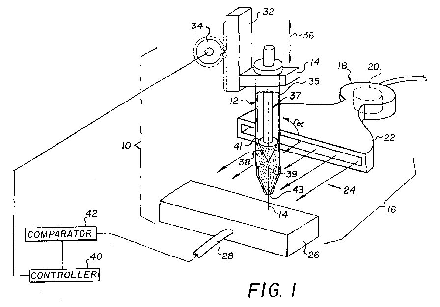
- the detecting apparatus 10 of the invention for detecting improper liquid in a metering tip 12 having an axis 14, used in an otherwise conventional clinical analyzer comprises a scanner 16 which in turn comprises a light source 18, such as an LED 20 that illuminates a light guide 22 to direct a linear beam 24 across a span to a detector 26, which is preferably a conventional linear CCD array, the LED and array being constructed to emit and detect, respectively, light of one or more wavelengths between about 630 and 2000 nm. Below 630, there is too much interference from the absorption caused by bilirubin and hemoglobin. A highly preferred wavelength is 880 nm.
- Detector 26 in turn transmits via line 28 a signal in volts that represents the light that is transmitted in inverse proportion to the amount of liquid that intercepts the beam 24.
- a tip holder 30 mounts tip 14 and is connected to an elevator such as rack 32 and drive pinion 34 driven by a conventional motor, not shown, to move tip 12, arrow 36, past beam 24 to allow scanner 16 to scan the tip at each vertical portion along axis 14, at an angle alpha where alpha is generally 90 degrees, that is, generally normal to the tip axis 14.
- an elevator such as rack 32 and drive pinion 34 driven by a conventional motor, not shown, to move tip 12, arrow 36, past beam 24 to allow scanner 16 to scan the tip at each vertical portion along axis 14, at an angle alpha where alpha is generally 90 degrees, that is, generally normal to the tip axis 14.
- "generally" when applied to this context means, plus or minus 10 degrees.
- scans are obtained for tip portions spaced vertically along the tip axis.
- An example of the spacing of the portions is a distance of between about 0.001 mm and about 1 mm.
- Any tip 12 can be used, but preferably it includes a hollow body 35 and an interior, electrically conductive plunger 37 driven along axis 14 by a conventional motor, not shown.
- Plunger 37 is conventional and includes a cone 38 that wipes against the inside surface 39 of tip 12 at a wipe line 41, to create partial vacuum or partial pressure to aspirate in or drive out liquid (shown as speckles in Fig. 1).
- Plunger 32 is electrically conductive so as to be able to detect, when cone 38 is at the bottom of tip 12, liquid levels of the container from which liquid is to be aspirated.
- a conventional controller 40 is connected to the motor driving gear 34, to ensure that signals collected by a conventional comparator 42 are collected for a plurality of adjacent portions of the tip representing all levels within the tip where liquid should be present, including just below aperture 43 of the tip where a drop of liquid might be pendant, and just above where liquid should be.
- Comparator 42 in turn compares the light transmitted through a tip of "unknown" condition, with the light transmission known to exist for the same tip containing bubble-free liquid at each of the adjacent portions of the tip, that is, liquid in contact with and below cone 38.
- controller 40 and comparator 44 are preferably and conveniently both part of electronics well-known to those skilled in the art.
- Fig. 2 In the method of the invention, one alternative noted above produces the result of Fig. 2. That is, using preferably the apparatus of Fig. 1, liquid is first aspirated into tip 12 to nominally fill it, as shown in Fig. 1. Tip 12 is then lowered, arrow 36, to scan the tip with beam 24. (Alternatively, but this is more cumbersome, tip 12 can be maintained stationary and scanner 16 moved relative to it.) As tip 12 passes through beam 24, comparator 42 receives transmission signals for each of the several positions within tip 12 where liquid nominally exists, that is, from the lowest position in tip 12 up to the point where cone 38 is in wiping contact with side surface 39. A transmission signal is also received for a position below the tip to detect any pendant drop, as well as above the cone-wiping position to detect whether liquid has been improperly ejected above the cone.
- comparator 42 From each tip portion signal, comparator 42 "subtracts" out the transmission signal produced by a dry tip but with plunger 37 in the same raised position, and an absolute value of the difference signal is produced.
- the absolute value of the difference signal noted above is integrated, or summed, over all the scanning positions, to obtain a total value of transmittance due solely to the liquid (the dry tip "blank” values having been subtracted).
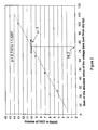
- Fig. 2 is a calibration plot of the integrated absolute values of transmission for the tip in question and is obtained by plotting the values of transmission less the subtracted dry-tip blank values of each portion scanned, integrated over the entire tip from aperture 43 to wipe line 41, for either a) 4 microliters of liquid and 6 microliters of air bubbles, b) 7 microliters of liquid and 3 microliters of air, c) 9 microliters of liquid and 1 microliter of air, d) 10 microliters of liquid and no air bubbles, and e) 13 microliters of liquid and no air bubbles. Only the absolute values so integrated are plotted.
- Comparator 42 then takes the reading for the tip of "unknown" condition, and locates the summed absolute value of the signal on the x-axis. For this particular plot, if the intersect is not at the point produced by a summed signal of 75.2 volts ⁇ 7 volts, which is the value on the dashed line for 10 microliters of liquid, then the signal is representative of an error in that the nominal liquid volume of 10 ⁇ L and zero air bubbles is not present.
- This graph represents a look-up table in the analyzer, and the microprocessor therefor need only take the voltage of the transmission values and determine if it is within ⁇ 7 volts of 75.2.
- the plot of Fig. 2 does not account for any liquid pendant from the tip below aperture 43, nor liquid squeezed past plunger 38 above wipe line 41.
- the scans taken below aperture 43 and above wipe line 41 are examined, either before or after subtracting the dry-tip "blank" value. If they are not within a predetermined range of values for no liquid present, then the reading indicates an abnormality is present, and the tip reading is flagged as being in error, that is, not within the predetermined range of known total values for nominal liquid volumes.
- the "nominal volume" is one in which no liquid appears below aperture 43 as a pendant drop or above wipe line 41.
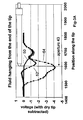
- Figs. 3A and 3B illustrate the validity of the extra step of evaluating the scan below aperture 43.
- the dry-tip blank transmission values have been subtracted.
- the numbers along the x-axis are arbitrary distance values.
- a tip with no pendent drop produced curve 50, which, at the scan at or below aperture 43, gave a reading less than -0.5 volts.
- curve 52 shows a voltage value greater than -0.5 at and below aperture 43. That is, at aperture 43 the voltage reading is -1.0.
- Curve 54 represents a pendant drop of 5 ⁇ L. It is further estimated that a 1 ⁇ L pendent drop will produce a voltage value upon scanning at or below aperture 43, of -0.5 volts. Any pendant drop smaller than 1 ⁇ L in volume can be disregarded.
- the predetermined range allowed for the scan below the tip aperture is an absolute value less than 0.5 volts.
- curve 60 represents no pendant drop, producing a voltage value of 4.8 - 4.9 volts at or below aperture 43.
- a pendant drop of 3 ⁇ L produces, curve 62, a voltage value of 3.4 volts at aperture 43, and of 5 ⁇ L curve 64 produces a value of about 1.0 volts. It is expected a pendant drop of 1 ⁇ L will produce a value of about 4.5 volts.
- the predetermined range of acceptable values is 4.6 to 4.9 volts. Anything outside of this when not subtracting a dry-tip blank is flagged as being in error.
- Figs. 4 through 12 are illustrative of an alternative technique for comparing the tip in an unknown condition with the transmission values for a tip with perfect conditions, that is, with liquid present only at levels between the aperture 43 and the wipe line 41, free of air bubbles.
- the actual transmission values in volts, detected for each portion by scanning as described above is mapped over a two-dimensional representation of the tip in cross-section, and the map is compared with the map produced by a tip with liquid present under perfect conditions.
- the map is representative of a cross-section taken generally vertically through axis 14 of the tip. Scans were all taken at 880 nm.
- the x-axis values are ⁇ horizontal distances taken from axis 14, whereas the vertical axis values are distances vertically from an arbitrary zero point, which zero point is maintained even in Figs. 10-11 that map a higher portion of the tip.
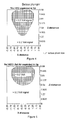
- a mapped image is shown of a tip properly filled with liquid between aperture 43 and wipe line 41 with no air bubbles present.
- the curve that is shown is the boundary for transmission null voltages of less than 0.2 volts, representing just the liquid. This is to be contrasted with the mapped images of Figs. 5 and 6.
- the tip was first filled with 5 ⁇ L of H 2 O and then 5 ⁇ L of air. The result is a large air bubble at the bottom portion of the tip just above aperture 43.
- the contour lines of the transmission voltage values show a marked loss of null voltages at the bottom portion, labeled "> 0.2 volts".
- comparator 42 electronically compares the two dimensional maps of the unknown tip conditions and the perfect tip conditions, for deviations in the contour lines of the former, over the two dimensions, that exceed 0.1 volts. That is, the voltage values of the pixels of the test map are subtracted by the analyzer from the voltage values of the same pixels on the reference or "perfect" map, to determine if there is any difference value anywhere, that is greater than 0.1 volts.
- Fig. 7 illustrates the comparison results in absolute values, wherein the tip was properly filled with no air bubbles.
- the test plot is not shown but was substantially identical to that of Fig. 4.
- Fig. 7 is a plot that has no data points, and represents a successful filling of the tip.
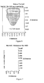
- the comparison plot of Fig. 8 also in absolute values, shows a large area of > 0.1 volt difference, precisely in the truncated area that is "missing" in Fig. 5.
- Fig. 9 indicates in a comparison plot, delta or difference voltages > 0.1 volts precisely at the areas of the necked in portion, Fig. 6. It is the presence of any data points in Figs. 8 or 9 (stored as a look-up table in the microprocessor) that cause the analyzer to issue an error message.
- Fig. 10 is a map similar to that of Fig. 4, but of the plunger portion of the tip above wipe line 41.
- the plunger portion of the tip represented by the map of Fig. 10 is free of any liquid above wipe line 41.
- the tip portion mapped in Fig. 11, which likewise is the plunger portion above wipe line 41 has 12 ⁇ L of H 2 O above the wipe line. (The tips for both Figs. 10 and 11 also had 10 ⁇ L of H 2 O below the wipe line.)
- the map of the contour lines of Fig. 11 is readily different in appearance from that of Fig. 10. E.g., necking-in is noted at Z-distance 5.4, representative of liquid above wipe line 41.
- the comparison plot of Fig. 12 shows error data in four different clumps, representative of the visual differences between Fig. 11 and Fig. 10.
Landscapes
- General Health & Medical Sciences (AREA)
- Health & Medical Sciences (AREA)
- Life Sciences & Earth Sciences (AREA)
- Chemical & Material Sciences (AREA)
- Analytical Chemistry (AREA)
- Biochemistry (AREA)
- Physics & Mathematics (AREA)
- General Physics & Mathematics (AREA)
- Immunology (AREA)
- Pathology (AREA)
- Automatic Analysis And Handling Materials Therefor (AREA)
- Investigating Or Analysing Materials By Optical Means (AREA)
- Investigating Or Analysing Materials By The Use Of Chemical Reactions (AREA)
Abstract
Description
Claims (11)
- A method of detecting the status of aqueous liquid in a dispensing tip having an axis and being capable of transmitting light therethrough of radiation having wavelengths between about 630 and about 2000 nm, comprising the steps of:a) aspirating the liquid into one of said tips to fill the tip to a nominal level;b) scanning the liquid in said tip by a scanner comprising a light source and a light detector that emits and detects, respectively, radiation at one of said wavelengths;c) providing relative motion between said tip and said scanner while said step b) is conducted, so that said scanner scans from a first position above where a pendant drop of the aqueous liquid would be located on said tip if present, to a predetermined second position which represents said nominal level;d) while conducting steps b) and c), separately detecting at each of several portions of the tip between and including said first and second positions, the amount of light transmitted to said detector at said one wavelength, so that all liquid-containing levels within the tip are detected;e) subtracting the amount of light transmitted in step d) from the amount transmitted through said tip when no liquid is present, for each of said several portions, to obtain a transmittance value caused by the amount of liquid present, in each of said portions;f) integrating said transmittance values from step e) for each of said several portions to obtain a total value of transmittance, in said tip, due to liquid present;g) comparing said total value of transmittance with total values known to exist for selected nominal liquid volumes free of air bubbles;h) repeating steps c) and d) for a position below said first position where a pendant drop might be present and above said second position where extraneous liquid might be present;i) comparing the value of light transmitted at both said below and above positions against a value transmitted with no liquid present at said below and above positions, respectively; andj) flagging the results as being in error if the comparison of step g) is not within a predetermined range for the selected nominal liquid volume, or if the comparison in step i) is not within a predetermined range of the value with no liquid present for either said below or above position.
- A method of detecting the status of aqueous liquid in a dispensing tip having an axis and being capable of transmitting light therethrough of radiation having wavelengths between about 630 and about 2000 nm, comprising the steps of:a) aspirating the liquid into one of said tips to fill the tip to a nominal level;b) scanning the liquid in said tip by a scanner comprising a light source and a light detector that emits and detects, respectively, radiation at one of said wavelengths;c) providing relative motion between said tip and said scanner while said step b) is conducted, so that said scanner scans from a first position below said tip where a pendant drop of the aqueous liquid would be located if present, to a predetermined second position above said first position that represents said nominal level;d) while conducting steps b) and c), separately detecting at each of several portions of the tip between and including said first and second positions, the amount of light transmitted to said detector at said one wavelength, so that all liquid-containing levels within the tip are detected;e) mapping said amounts of light transmitted over a two-dimensional representation of the tip cross-section taken through the tip axis;f) comparing the mapped values against known mapped values for a tip containing liquid free of air bubbles, located only between said first and second positions; andg) flagging the results as being in error if the comparison of step f) detects a mismatch beyond a preselected deviant value.
- The method of claim 1 or claim 2, wherein said portions are spaced apart a distance that is between .001 mm and lmm.
- The method of any one of claims 1 to 3, wherein said one wavelength is about 880 nm.
- The method of any one of claims 1 to 4 wherein said light source is an LED.
- The method of any one of claims 1 to 5, wherein said scanning step directs said radiation at an angle to said tip axis that is generally 90°.
- Apparatus for detecting improper liquid content of a metering tip of an analyzer, the tip having an axis, the apparatus comprising:a) a scanner comprising a light source, a light detector, and means for transmitting light from said source to said detector at a wavelength which is between about 630 and about 2000 nm;b) moving means for providing relative motion of one of said tips past said scanner so that said scanner scans said tip and its contents;c) a controller of said moving means and said detector that directs said detector to detect light transmitted through the tip to said detector at at least several adjacent portions of said tip, as well as just below said tip where any pendant drop would be located; andd) a comparator that compares the light transmitted at said several levels with that known to represent the tip containing bubble-free liquid at each of said levels.
- Apparatus of claim 7, wherein said light source and light detector operate at about 880 nm.
- Apparatus of claim 7 or claim 8, wherein said scanner directs said radiation at an angle to said tip axis that is generally 90°.
- Apparatus of any one of claims 7 to 9, and further including in combination, a metering tip and means for mounting said tip on said moving means, said tip comprising a hollow body and an electrically conductive plunger within said body.
- A method of detecting the status of aqueous liquid in a dispensing tip having an axis of symmetry and which is capable of transmitting light therethrough of radiation between 630 and 2000 nm, comprising the steps of:a) aspirating the liquid into one of said tips to fill the tip to a nominal level;b) scanning the liquid in said tip by a scanner comprising a light source and a light detector, said source and detector being aligned along a direction that is generally normal to said tip axis;c) providing relative motion between said tip and said scanner while said step b) is conducted, so that said scanner scans from a first position below said tip where a pendant drop of the aqueous liquid would be located if present, to a predetermined second position above said first position that represents said nominal level;d) while conducting steps b) and c), separately detecting at each of several portions of the tip between and including said first and second positions, the amount of light transmitted to said detector, so that all liquid-containing levels within the tip are detected;e) comparing said detected light of step d) with light known to be transmitted if liquid is present only at all of said levels, free of air bubbles; andf) flagging the results as being in error if water is detected at said first position; or if it is not detected because of air bubbles at any one of said levels within said tip up to and including said second position; or if it is detected above said second position.
Applications Claiming Priority (2)
| Application Number | Priority Date | Filing Date | Title |
|---|---|---|---|
| US8320898P | 1998-04-27 | 1998-04-27 | |
| US83208P | 1998-04-27 |
Publications (3)
| Publication Number | Publication Date |
|---|---|
| EP0953843A2 true EP0953843A2 (en) | 1999-11-03 |
| EP0953843A3 EP0953843A3 (en) | 2000-09-06 |
| EP0953843B1 EP0953843B1 (en) | 2003-12-10 |
Family
ID=22176874
Family Applications (1)
| Application Number | Title | Priority Date | Filing Date |
|---|---|---|---|
| EP99303195A Expired - Lifetime EP0953843B1 (en) | 1998-04-27 | 1999-04-26 | Incremental absorbance scanning of liquid in dispensing tips |
Country Status (7)
| Country | Link |
|---|---|
| US (1) | US6235534B1 (en) |
| EP (1) | EP0953843B1 (en) |
| JP (1) | JPH11337559A (en) |
| AT (1) | ATE256292T1 (en) |
| AU (1) | AU760266B2 (en) |
| CA (1) | CA2269750C (en) |
| DE (1) | DE69913424T2 (en) |
Cited By (6)
| Publication number | Priority date | Publication date | Assignee | Title |
|---|---|---|---|---|
| EP1566625A1 (en) | 2004-02-23 | 2005-08-24 | Ortho-Clinical Diagnostics, Inc. | Method for determining an analyte by multiple measurements through a cuvette |
| EP1243929A4 (en) * | 1999-12-28 | 2005-10-19 | Prec System Science Co Ltd | OPERATION CONTROL DEVICE AND DISTRIBUTOR CONTROL METHOD |
| EP1760472A1 (en) * | 2005-08-29 | 2007-03-07 | Sysmex Corporation | Method and apparatus for monitoring sample aspiration. |
| EP2112514A1 (en) * | 2008-04-24 | 2009-10-28 | bioMérieux BV | Method and apparatus for checking the fluid in a pipet tip |
| US20110126645A1 (en) * | 2006-04-03 | 2011-06-02 | Artel, Inc. | Apparatus and method for aspirating and dispensing liquid |
| WO2017002329A1 (en) * | 2015-06-30 | 2017-01-05 | Nihon Kohden Corporation | Method and apparatus for analyzing blood |
Families Citing this family (37)
| Publication number | Priority date | Publication date | Assignee | Title |
|---|---|---|---|---|
| US6391149B1 (en) * | 1998-06-04 | 2002-05-21 | Advanced Cardiovascular Systems, Inc. | Method and apparatus for concentrating a solute in solution with a solvent |
| JP4606543B2 (en) * | 2000-04-13 | 2011-01-05 | パナソニック株式会社 | Method for confirming amount of solution to be measured and measuring system control method in optical property measuring apparatus |
| US6861034B1 (en) * | 2000-11-22 | 2005-03-01 | Xerox Corporation | Priming mechanisms for drop ejection devices |
| US6943036B2 (en) * | 2001-04-30 | 2005-09-13 | Agilent Technologies, Inc. | Error detection in chemical array fabrication |
| US6739478B2 (en) * | 2001-06-29 | 2004-05-25 | Scientific Products & Systems Llc | Precision fluid dispensing system |
| US7473897B2 (en) * | 2001-09-12 | 2009-01-06 | Tecan Trading Ag | System, method, and computer program for conducting optical transmission measurements and evaluating determined measuring variables |
| US8986944B2 (en) | 2001-10-11 | 2015-03-24 | Aviva Biosciences Corporation | Methods and compositions for separating rare cells from fluid samples |
| US8980568B2 (en) * | 2001-10-11 | 2015-03-17 | Aviva Biosciences Corporation | Methods and compositions for detecting non-hematopoietic cells from a blood sample |
| US7166443B2 (en) * | 2001-10-11 | 2007-01-23 | Aviva Biosciences Corporation | Methods, compositions, and automated systems for separating rare cells from fluid samples |
| US20050043407A1 (en) * | 2003-08-22 | 2005-02-24 | Pfizer Inc | Pharmaceutical composition for the prevention and treatment of addiction in a mammal |
| US20050101025A1 (en) * | 2003-11-12 | 2005-05-12 | Ho Winston Z. | Apparatus for proteins and nucleic acids analysis |
| JP4753645B2 (en) * | 2005-07-11 | 2011-08-24 | ベックマン コールター, インコーポレイテッド | Automatic analyzer |
| WO2007124346A2 (en) * | 2006-04-19 | 2007-11-01 | Archivex Llc | Micro-drop detection and detachment |
| JP2007303937A (en) * | 2006-05-10 | 2007-11-22 | Olympus Corp | Autoanalyzer |
| CN101583722A (en) * | 2006-07-14 | 2009-11-18 | 阿维瓦生物科学股份有限公司 | Methods and compositions for detecting rare cells from a biological sample |
| US11174458B2 (en) | 2007-04-23 | 2021-11-16 | Koligo Therapeutics, Inc. | Cell separation apparatus and methods of use |
| US8088593B2 (en) | 2007-10-02 | 2012-01-03 | Theranos, Inc. | Modular point-of-care devices, systems, and uses thereof |
| US8136690B2 (en) | 2009-04-14 | 2012-03-20 | Microsoft Corporation | Sensing the amount of liquid in a vessel |
| CN106323875B (en) | 2011-01-21 | 2019-07-09 | 西拉诺斯知识产权有限责任公司 | Sample uses maximized system and method |
| JP5850665B2 (en) * | 2011-08-02 | 2016-02-03 | 栄研化学株式会社 | Immunoassay device and immunoassay method |
| CA3009281C (en) * | 2011-09-09 | 2021-10-19 | Gen-Probe Incorporated | Automated sample handling instrumentation, systems, processes, and methods |
| US20140170735A1 (en) | 2011-09-25 | 2014-06-19 | Elizabeth A. Holmes | Systems and methods for multi-analysis |
| US9632102B2 (en) | 2011-09-25 | 2017-04-25 | Theranos, Inc. | Systems and methods for multi-purpose analysis |
| US9664702B2 (en) | 2011-09-25 | 2017-05-30 | Theranos, Inc. | Fluid handling apparatus and configurations |
| US8475739B2 (en) | 2011-09-25 | 2013-07-02 | Theranos, Inc. | Systems and methods for fluid handling |
| US10012664B2 (en) | 2011-09-25 | 2018-07-03 | Theranos Ip Company, Llc | Systems and methods for fluid and component handling |
| US9810704B2 (en) | 2013-02-18 | 2017-11-07 | Theranos, Inc. | Systems and methods for multi-analysis |
| JP2015532428A (en) * | 2012-10-12 | 2015-11-09 | コーニンクレッカ フィリップス エヌ ヴェKoninklijke Philips N.V. | Optical filling detection |
| US10422806B1 (en) | 2013-07-25 | 2019-09-24 | Theranos Ip Company, Llc | Methods for improving assays of biological samples |
| GB2525679A (en) * | 2014-05-02 | 2015-11-04 | Univ Singapore | A disposable measurement tip and method for use thereof |
| EP4032714B1 (en) | 2014-10-21 | 2023-12-06 | Gen-Probe Incorporated | Method and apparatus for sample transfer comprising a printing module |
| ES2922878T3 (en) | 2016-10-28 | 2022-09-21 | Becton Dickinson Co | Positive Dispense Verification Sensor |
| BR112019008270A8 (en) | 2016-10-28 | 2023-04-11 | Beckman Coulter Inc | SUBSTANCE PREPARATION EVALUATION SYSTEM |
| DE102017212196A1 (en) * | 2017-07-17 | 2019-01-17 | Robert Bosch Gmbh | Method and control device for detecting bubbles in a fluid chamber of a fluidic system and fluidic system |
| US12163885B2 (en) * | 2018-08-31 | 2024-12-10 | Shimadzu Corporation | Analysis device, analysis method, trace liquid collection device, and trace liquid collection method |
| CN113660961A (en) * | 2018-12-13 | 2021-11-16 | 科力果疗法公司 | Cell separation device and method of use |
| WO2023042143A1 (en) * | 2021-09-16 | 2023-03-23 | Thermo Fisher Scientific S.P.A. | Process for analyzing of a liquid sample with bubble detection |
Family Cites Families (10)
| Publication number | Priority date | Publication date | Assignee | Title |
|---|---|---|---|---|
| JPS57168165A (en) * | 1981-04-10 | 1982-10-16 | Nippon Tectron Co Ltd | Method of and apparatus for checking suction of sample in clinically automatic chemical analyzer |
| JPS6086439A (en) | 1983-10-19 | 1985-05-16 | Toshiba Corp | Optical quantifying device of very small quantity |
| US5328822A (en) * | 1990-04-23 | 1994-07-12 | Solid State Farms, Inc. | Apparatus and method for sedimentation based blood analysis |
| DE4023165A1 (en) | 1990-07-20 | 1992-01-23 | Kodak Ag | DEVICE FOR SCANING AND CENTERING CONTAINERS WITH A LIQUID |
| JPH05223830A (en) * | 1991-04-04 | 1993-09-03 | Olympus Optical Co Ltd | Method and device for detecting dispensated quantity |
| EP0619476B1 (en) | 1992-12-19 | 1999-09-22 | Boehringer Mannheim Gmbh | Device for detection of a fluidic interface in a transparent measuring tube |
| JPH08338849A (en) * | 1995-04-11 | 1996-12-24 | Precision Syst Sci Kk | Liquid suction determination method and dispensing device driven and controlled by this method |
| EP0801309A3 (en) * | 1996-04-08 | 1998-08-12 | SANYO ELECTRIC Co., Ltd. | Pipetting apparatus |
| US5955378A (en) * | 1997-08-20 | 1999-09-21 | Challener; William A. | Near normal incidence optical assaying method and system having wavelength and angle sensitivity |
| US6113858A (en) * | 1998-01-26 | 2000-09-05 | Tang; Ruey-Long | Monitor with in-situ optical probe for continuous concentration measurements |
-
1999
- 1999-03-09 US US09/264,806 patent/US6235534B1/en not_active Expired - Fee Related
- 1999-04-22 CA CA002269750A patent/CA2269750C/en not_active Expired - Fee Related
- 1999-04-26 AT AT99303195T patent/ATE256292T1/en not_active IP Right Cessation
- 1999-04-26 AU AU23975/99A patent/AU760266B2/en not_active Ceased
- 1999-04-26 EP EP99303195A patent/EP0953843B1/en not_active Expired - Lifetime
- 1999-04-26 DE DE69913424T patent/DE69913424T2/en not_active Expired - Lifetime
- 1999-04-27 JP JP11119747A patent/JPH11337559A/en active Pending
Cited By (13)
| Publication number | Priority date | Publication date | Assignee | Title |
|---|---|---|---|---|
| EP1243929A4 (en) * | 1999-12-28 | 2005-10-19 | Prec System Science Co Ltd | OPERATION CONTROL DEVICE AND DISTRIBUTOR CONTROL METHOD |
| EP1566625A1 (en) | 2004-02-23 | 2005-08-24 | Ortho-Clinical Diagnostics, Inc. | Method for determining an analyte by multiple measurements through a cuvette |
| US7307718B2 (en) | 2004-02-23 | 2007-12-11 | Ortho-Clinical Diagnostics, Inc. | Determining an analyte by multiple measurements through a cuvette |
| EP1760472A1 (en) * | 2005-08-29 | 2007-03-07 | Sysmex Corporation | Method and apparatus for monitoring sample aspiration. |
| US8821791B2 (en) | 2005-08-29 | 2014-09-02 | Sysmex Corporation | Monitoring method, monitoring apparatus and liquid sample analyzer |
| US8252235B2 (en) | 2005-08-29 | 2012-08-28 | Sysmex Corporation | Monitoring method, monitoring apparatus, and liquid sample analyzer |
| US20110126645A1 (en) * | 2006-04-03 | 2011-06-02 | Artel, Inc. | Apparatus and method for aspirating and dispensing liquid |
| US8850903B2 (en) * | 2006-04-03 | 2014-10-07 | Artel, Inc. | Apparatus and method for aspirating and dispensing liquid |
| WO2009130309A1 (en) * | 2008-04-24 | 2009-10-29 | bioMérieux B.V. | Method and apparatus for checking the fluid in a pipet tip |
| EP2112514A1 (en) * | 2008-04-24 | 2009-10-28 | bioMérieux BV | Method and apparatus for checking the fluid in a pipet tip |
| US8885041B2 (en) | 2008-04-24 | 2014-11-11 | Biomerieux B.V. | Method and apparatus for checking the fluid in a pipet tip |
| WO2017002329A1 (en) * | 2015-06-30 | 2017-01-05 | Nihon Kohden Corporation | Method and apparatus for analyzing blood |
| US10859591B2 (en) | 2015-06-30 | 2020-12-08 | Nihon Kohden Corporation | Method and apparatus for analyzing blood |
Also Published As
| Publication number | Publication date |
|---|---|
| DE69913424D1 (en) | 2004-01-22 |
| DE69913424T2 (en) | 2004-10-14 |
| AU760266B2 (en) | 2003-05-08 |
| AU2397599A (en) | 1999-11-04 |
| CA2269750A1 (en) | 1999-10-27 |
| ATE256292T1 (en) | 2003-12-15 |
| EP0953843A3 (en) | 2000-09-06 |
| US6235534B1 (en) | 2001-05-22 |
| CA2269750C (en) | 2007-03-20 |
| EP0953843B1 (en) | 2003-12-10 |
| JPH11337559A (en) | 1999-12-10 |
Similar Documents
| Publication | Publication Date | Title |
|---|---|---|
| EP0953843B1 (en) | Incremental absorbance scanning of liquid in dispensing tips | |
| US10429401B2 (en) | Methods and systems for tube inspection and liquid level detection | |
| JP4342643B2 (en) | Dynamic contactless detection to determine the characteristics of an analytical container using ultrasound | |
| EP0866336B1 (en) | Liquid suction examination method and dispensation apparatus driving-controlled by the same | |
| US9915675B2 (en) | Methods and apparatus for determining aspiration and/or dispensing volume and/or pipette positioning | |
| EP2277053B1 (en) | Method and apparatus for checking the fluid in a pipet tip | |
| US20240133908A1 (en) | Methods and apparatus adapted to identify 3d center location of a specimen container using a single image capture device | |
| JPH06221895A (en) | Detecting device for fluid-phase boundary in transparent measuring pipe and accurate automatic measuring device for flow rate | |
| EP0694784B1 (en) | Liquid sampling apparatus | |
| JP2010071766A (en) | Dispensing device, automatic analyzing apparatus, and dispensing failure confirming method | |
| JP7668091B2 (en) | Apparatus for optically monitoring the administration of a pipetted liquid - Patent application | |
| US7569183B2 (en) | Fecal assay method and analyzer | |
| KR102238130B1 (en) | Apparatus for inspecting droplet | |
| EP4216170A1 (en) | Instrument parameter determination based on sample tube identification | |
| US20240142484A1 (en) | Automatic Analyzer | |
| JP4092312B2 (en) | Interface detection device and method, volume measuring device | |
| CN114324924A (en) | Supporting measurement of a liquid sample | |
| JP3024890B2 (en) | Disposable tip and dispensing device using the tip | |
| JP2000046624A (en) | Analyser having liquid residual quantity detecting function | |
| US20260056223A1 (en) | Cuvette for analyzing a fluid | |
| CA2183639C (en) | Method for sucking/determining liquid and pipetting device driven and controlled according to method | |
| WO2024101025A1 (en) | Automatic analyzer | |
| Liu | Optical systems to evaluate volume of medical samples in opaque test tubes |
Legal Events
| Date | Code | Title | Description |
|---|---|---|---|
| PUAI | Public reference made under article 153(3) epc to a published international application that has entered the european phase |
Free format text: ORIGINAL CODE: 0009012 |
|
| AK | Designated contracting states |
Kind code of ref document: A2 Designated state(s): AT BE CH CY DE DK ES FI FR GB GR IE IT LI LU MC NL PT SE |
|
| AX | Request for extension of the european patent |
Free format text: AL;LT;LV;MK;RO;SI |
|
| PUAL | Search report despatched |
Free format text: ORIGINAL CODE: 0009013 |
|
| AK | Designated contracting states |
Kind code of ref document: A3 Designated state(s): AT BE CH CY DE DK ES FI FR GB GR IE IT LI LU MC NL PT SE |
|
| AX | Request for extension of the european patent |
Free format text: AL;LT;LV;MK;RO;SI |
|
| 17P | Request for examination filed |
Effective date: 20010213 |
|
| AKX | Designation fees paid |
Free format text: AT BE CH CY DE DK ES FI FR GB GR IE IT LI LU MC NL PT SE |
|
| GRAH | Despatch of communication of intention to grant a patent |
Free format text: ORIGINAL CODE: EPIDOS IGRA |
|
| GRAS | Grant fee paid |
Free format text: ORIGINAL CODE: EPIDOSNIGR3 |
|
| GRAA | (expected) grant |
Free format text: ORIGINAL CODE: 0009210 |
|
| AK | Designated contracting states |
Kind code of ref document: B1 Designated state(s): AT BE CH CY DE DK ES FI FR GB GR IE IT LI LU MC NL PT SE |
|
| PG25 | Lapsed in a contracting state [announced via postgrant information from national office to epo] |
Ref country code: NL Free format text: LAPSE BECAUSE OF FAILURE TO SUBMIT A TRANSLATION OF THE DESCRIPTION OR TO PAY THE FEE WITHIN THE PRESCRIBED TIME-LIMIT Effective date: 20031210 Ref country code: IT Free format text: LAPSE BECAUSE OF FAILURE TO SUBMIT A TRANSLATION OF THE DESCRIPTION OR TO PAY THE FEE WITHIN THE PRESCRIBED TIME-LIMIT;WARNING: LAPSES OF ITALIAN PATENTS WITH EFFECTIVE DATE BEFORE 2007 MAY HAVE OCCURRED AT ANY TIME BEFORE 2007. THE CORRECT EFFECTIVE DATE MAY BE DIFFERENT FROM THE ONE RECORDED. Effective date: 20031210 Ref country code: FI Free format text: LAPSE BECAUSE OF FAILURE TO SUBMIT A TRANSLATION OF THE DESCRIPTION OR TO PAY THE FEE WITHIN THE PRESCRIBED TIME-LIMIT Effective date: 20031210 Ref country code: CY Free format text: LAPSE BECAUSE OF FAILURE TO SUBMIT A TRANSLATION OF THE DESCRIPTION OR TO PAY THE FEE WITHIN THE PRESCRIBED TIME-LIMIT Effective date: 20031210 Ref country code: BE Free format text: LAPSE BECAUSE OF FAILURE TO SUBMIT A TRANSLATION OF THE DESCRIPTION OR TO PAY THE FEE WITHIN THE PRESCRIBED TIME-LIMIT Effective date: 20031210 Ref country code: AT Free format text: LAPSE BECAUSE OF FAILURE TO SUBMIT A TRANSLATION OF THE DESCRIPTION OR TO PAY THE FEE WITHIN THE PRESCRIBED TIME-LIMIT Effective date: 20031210 |
|
| REG | Reference to a national code |
Ref country code: GB Ref legal event code: FG4D |
|
| REG | Reference to a national code |
Ref country code: CH Ref legal event code: EP |
|
| REG | Reference to a national code |
Ref country code: IE Ref legal event code: FG4D |
|
| REF | Corresponds to: |
Ref document number: 69913424 Country of ref document: DE Date of ref document: 20040122 Kind code of ref document: P |
|
| PG25 | Lapsed in a contracting state [announced via postgrant information from national office to epo] |
Ref country code: SE Free format text: LAPSE BECAUSE OF FAILURE TO SUBMIT A TRANSLATION OF THE DESCRIPTION OR TO PAY THE FEE WITHIN THE PRESCRIBED TIME-LIMIT Effective date: 20040310 Ref country code: GR Free format text: LAPSE BECAUSE OF FAILURE TO SUBMIT A TRANSLATION OF THE DESCRIPTION OR TO PAY THE FEE WITHIN THE PRESCRIBED TIME-LIMIT Effective date: 20040310 Ref country code: DK Free format text: LAPSE BECAUSE OF FAILURE TO SUBMIT A TRANSLATION OF THE DESCRIPTION OR TO PAY THE FEE WITHIN THE PRESCRIBED TIME-LIMIT Effective date: 20040310 |
|
| REG | Reference to a national code |
Ref country code: CH Ref legal event code: NV Representative=s name: E. BLUM & CO. PATENTANWAELTE |
|
| PG25 | Lapsed in a contracting state [announced via postgrant information from national office to epo] |
Ref country code: ES Free format text: LAPSE BECAUSE OF FAILURE TO SUBMIT A TRANSLATION OF THE DESCRIPTION OR TO PAY THE FEE WITHIN THE PRESCRIBED TIME-LIMIT Effective date: 20040321 |
|
| PG25 | Lapsed in a contracting state [announced via postgrant information from national office to epo] |
Ref country code: LU Free format text: LAPSE BECAUSE OF NON-PAYMENT OF DUE FEES Effective date: 20040426 Ref country code: IE Free format text: LAPSE BECAUSE OF NON-PAYMENT OF DUE FEES Effective date: 20040426 |
|
| PG25 | Lapsed in a contracting state [announced via postgrant information from national office to epo] |
Ref country code: MC Free format text: LAPSE BECAUSE OF NON-PAYMENT OF DUE FEES Effective date: 20040430 |
|
| NLV1 | Nl: lapsed or annulled due to failure to fulfill the requirements of art. 29p and 29m of the patents act | ||
| ET | Fr: translation filed | ||
| PLBE | No opposition filed within time limit |
Free format text: ORIGINAL CODE: 0009261 |
|
| STAA | Information on the status of an ep patent application or granted ep patent |
Free format text: STATUS: NO OPPOSITION FILED WITHIN TIME LIMIT |
|
| 26N | No opposition filed |
Effective date: 20040913 |
|
| REG | Reference to a national code |
Ref country code: IE Ref legal event code: MM4A |
|
| REG | Reference to a national code |
Ref country code: CH Ref legal event code: PFA Owner name: ORTHO-CLINICAL DIAGNOSTICS, INC. Free format text: ORTHO-CLINICAL DIAGNOSTICS, INC.#100 INDIGO CREEK DRIVE#ROCHESTER, NY 14626-5101 (US) -TRANSFER TO- ORTHO-CLINICAL DIAGNOSTICS, INC.#100 INDIGO CREEK DRIVE#ROCHESTER, NY 14626-5101 (US) |
|
| PG25 | Lapsed in a contracting state [announced via postgrant information from national office to epo] |
Ref country code: PT Free format text: LAPSE BECAUSE OF NON-PAYMENT OF DUE FEES Effective date: 20040510 |
|
| PGFP | Annual fee paid to national office [announced via postgrant information from national office to epo] |
Ref country code: CH Payment date: 20110412 Year of fee payment: 13 Ref country code: DE Payment date: 20110420 Year of fee payment: 13 Ref country code: FR Payment date: 20110426 Year of fee payment: 13 |
|
| PGFP | Annual fee paid to national office [announced via postgrant information from national office to epo] |
Ref country code: GB Payment date: 20110420 Year of fee payment: 13 |
|
| REG | Reference to a national code |
Ref country code: CH Ref legal event code: PL |
|
| GBPC | Gb: european patent ceased through non-payment of renewal fee |
Effective date: 20120426 |
|
| REG | Reference to a national code |
Ref country code: FR Ref legal event code: ST Effective date: 20121228 |
|
| PG25 | Lapsed in a contracting state [announced via postgrant information from national office to epo] |
Ref country code: LI Free format text: LAPSE BECAUSE OF NON-PAYMENT OF DUE FEES Effective date: 20120430 Ref country code: GB Free format text: LAPSE BECAUSE OF NON-PAYMENT OF DUE FEES Effective date: 20120426 Ref country code: CH Free format text: LAPSE BECAUSE OF NON-PAYMENT OF DUE FEES Effective date: 20120430 |
|
| REG | Reference to a national code |
Ref country code: DE Ref legal event code: R119 Ref document number: 69913424 Country of ref document: DE Effective date: 20121101 |
|
| PG25 | Lapsed in a contracting state [announced via postgrant information from national office to epo] |
Ref country code: FR Free format text: LAPSE BECAUSE OF NON-PAYMENT OF DUE FEES Effective date: 20120430 |
|
| PG25 | Lapsed in a contracting state [announced via postgrant information from national office to epo] |
Ref country code: DE Free format text: LAPSE BECAUSE OF NON-PAYMENT OF DUE FEES Effective date: 20121101 |