EP0953759B1 - Injector and ignition system for rocket engines - Google Patents
Injector and ignition system for rocket engines Download PDFInfo
- Publication number
- EP0953759B1 EP0953759B1 EP99303351A EP99303351A EP0953759B1 EP 0953759 B1 EP0953759 B1 EP 0953759B1 EP 99303351 A EP99303351 A EP 99303351A EP 99303351 A EP99303351 A EP 99303351A EP 0953759 B1 EP0953759 B1 EP 0953759B1
- Authority
- EP
- European Patent Office
- Prior art keywords
- orifice
- ignitor
- insert
- injector
- injector elements
- Prior art date
- Legal status (The legal status is an assumption and is not a legal conclusion. Google has not performed a legal analysis and makes no representation as to the accuracy of the status listed.)
- Expired - Lifetime
Links
- 239000007800 oxidant agent Substances 0.000 description 28
- 239000000446 fuel Substances 0.000 description 19
- 230000000153 supplemental effect Effects 0.000 description 6
- 238000002485 combustion reaction Methods 0.000 description 5
- 239000007788 liquid Substances 0.000 description 5
- 239000000463 material Substances 0.000 description 4
- 239000007921 spray Substances 0.000 description 4
- 238000010304 firing Methods 0.000 description 3
- 239000000203 mixture Substances 0.000 description 2
- 230000008014 freezing Effects 0.000 description 1
- 238000007710 freezing Methods 0.000 description 1
- 239000007789 gas Substances 0.000 description 1
- 230000003993 interaction Effects 0.000 description 1
- 238000013021 overheating Methods 0.000 description 1
- 238000010079 rubber tapping Methods 0.000 description 1
- 238000005507 spraying Methods 0.000 description 1
- 238000011144 upstream manufacturing Methods 0.000 description 1
- 238000003466 welding Methods 0.000 description 1
Images


Classifications
-
- B—PERFORMING OPERATIONS; TRANSPORTING
- B64—AIRCRAFT; AVIATION; COSMONAUTICS
- B64G—COSMONAUTICS; VEHICLES OR EQUIPMENT THEREFOR
- B64G1/00—Cosmonautic vehicles
- B64G1/22—Parts of, or equipment specially adapted for fitting in or to, cosmonautic vehicles
-
- F—MECHANICAL ENGINEERING; LIGHTING; HEATING; WEAPONS; BLASTING
- F02—COMBUSTION ENGINES; HOT-GAS OR COMBUSTION-PRODUCT ENGINE PLANTS
- F02K—JET-PROPULSION PLANTS
- F02K9/00—Rocket-engine plants, i.e. plants carrying both fuel and oxidant therefor; Control thereof
- F02K9/95—Rocket-engine plants, i.e. plants carrying both fuel and oxidant therefor; Control thereof characterised by starting or ignition means or arrangements
-
- F—MECHANICAL ENGINEERING; LIGHTING; HEATING; WEAPONS; BLASTING
- F02—COMBUSTION ENGINES; HOT-GAS OR COMBUSTION-PRODUCT ENGINE PLANTS
- F02K—JET-PROPULSION PLANTS
- F02K9/00—Rocket-engine plants, i.e. plants carrying both fuel and oxidant therefor; Control thereof
- F02K9/94—Re-ignitable or restartable rocket- engine plants; Intermittently operated rocket-engine plants
Definitions
- This invention relates to ignition systems for liquid fueled rocket engines, and more specifically, to an efficient system which increases the reliability of engine re-lights on multiple ignition launches.
- Liquid fueled rocket engines are commonly used as upper stage propulsion systems on multiple stage launch vehicles.
- an upper stage rocket engine may fire briefly, then coast, then fire again.
- Multiple firings of an engine during a single launch requires a highly reliable ignition system that is capable of multiple engine re-lights.
- Ignition systems of the prior art typically include a supplemental oxidizer supply line to provide additional oxidizer to the region surrounding the engine's ignitor during ignition to ensure proper lighting for re-lighting of the fuel/oxidizer mixture in the rocket engine's combustion chamber.
- the supplemental oxidizer supply line requires a shut-off valve to avoid over-heating. Combustion products back flow into the valve during the start-up pressurization of the engine, causing the valve to freeze closed. With the valve frozen closed for subsequent re-light attempts, the engine will not light reliably. Attempts to accommodate and/or eliminate back flow have proven to be ineffective at preventing freezing of the shut-off valve.
- US-A-4,621,492 (upon which the preamble to claim 1 is based) and US-A-3,662,960 disclose injector heads for rocket engines.
- US-A-5172,548 discloses an injector head for tapping off hot gases form a rocket combustor.
- an ignition system assembly as claimed in claim 1.
- the invention also extends to an ignition system incorporating such an assembly.
- a typical rocket engine 10 includes a thrust chamber 12, a combustion chamber 14 upstream of the thrust chamber 12, a faceplate 16 which contains a plurality of fuel/oxidizer injector elements 18 and an ignitor port 20, and an ignitor 22 mounted to the ignitor port 20, a fuel supply line 24 and an oxidizer supply line 26 for supplying fuel and oxidizer to the fuel/oxidizer injector elements 18, and a supplemental oxidizer supply system 28 for supplying additional oxidizer to the ignitor 22 during ignition.
- a faceplate 16 of a system incorporating the present invention has a centrally located ignitor port 20 and the ignitor 22 is mounted to the ignitor port 20.
- Radially outward of the port 20 is a first annular section 30 of ignitor elements 18, and radially outward of the first annular section 30 is a second annular section 32 of ignitor elements 18.
- a plurality of first injector elements 18' are located in the first annular section 30 of the faceplate 16 and a plurality of second injector elements 18" are located in the second annular section 32.
- each of the injector elements 18 has a first orifice 34 defining a first flow area, and a second annular orifice 36 defining a second flow area.
- the second annular orifice 36 is concentric with and radially outward of the first orifice 34 relative to the first orifice 34.
- the first orifice 34 of each injector element 18 provides oxidizer to the combustion chamber 14, and the second annular orifice 36 provides fuel to the combustion chamber 14.
- Each of the first injector elements 18' is located equidistant from the ignitor port 20, and as shown in FIG. 4, the second annular orifice 36 of each of the first injector elements 18' has a radially inner half 38 and a radially outer half 40.
- the radially inner half 38 is located between the radially outer half 40 and the ignitor port 20.
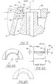
- At least one, and preferably several of the first injector elements 18' includes an insert 42 located in the second orifice 36 thereof. As shown in FIGS. 4 & 5, the insert blocks a portion of the second annular orifice 36, thereby reducing the second flow area of the second annular orifice 36 in which the insert 42 is located.
- the insert 42 comprises a semi cylindrical wall 44 having a thickness 46 that is only slightly less than the width 48 of the second annular orifice 36 in which the insert 42 is located.
- the term, "semi cylindrical wall” means a body generated by rotating a rectangular area having a thickness "T” and a height "H” at a distance "R” about a reference axis "A” for less than one complete revolution.
- the semi cylindrical wall 44 results from one half of a rotation about the reference axis A, and the thickness 46 is slightly less than the radial width 48 of the second annular orifice 36.
- the term "width of the second annular orifice” means the distance 48 between the radially inner surface 50 of the second annular orifice 36 and the radially outer surface 52 of that annular orifice 36, as shown in FIG. 5.
- a flange 54 which is integral with one end 56 of the semi cylindrical wall 44 extends radially outward therefrom in a direction that is substantially perpendicular to the reference axis "A".
- the insert 42 is preferably made of the same material as the faceplate 16, but may be made of a similar material having similar material properties as the material from which the faceplate 16 is made.
- inserts 42 are located in the radially inner half 38 of the second orifice 36 of at least half of the first injector elements 18'. As those skilled in the art will readily appreciate, the insert 42 reduces the second flow area of the second orifice 36 in which the insert 42 is located by approximately 50 percent, and since fuel is delivered through the second annular orifice 36 of each of the injectors 18, fuel flow through each of the first injector elements 18' in which the insert 42 is located is reduced by approximately 50 percent.
- the inserts 42 produce a fuel-lean (oxidizer-rich) zone immediately adjacent to the ignitor elements 18' in which the inserts 42 are located.
- each of the first injector elements 18' in which an insert 42 is located is immediately adjacent another first injector element 18' in which an insert 42 is located and immediately adjacent another first injector element 18' in which an insert 42 is not located.
- the first injector elements 18 ⁇ in which inserts 42 are not located are immediately adjacent two first injector elements 18 ⁇ in which inserts 42 are located.
- the inserts 42 are fixedly secured to the faceplate 16, preferably by welding the flange 54 thereto.
- fuel and oxidizer are fed to all of the injector elements 18 by the fuel supply line 24 and the oxidizer supply line 26, respectively. Due to the presence of the inserts 42 in the radially inner half 38 of the second annular orifice 36 of some of the first injector elements 18', fuel spray from the second annular orifice 36 of those injector elements 18' is directed away from the ignitor port 20, while a portion of the oxidizer spray from the first orifices 34 of the same injector elements 18 is directed toward the ignitor port 20.
- the injector elements 18' in which the inserts 42 are located therefore produce an oxidizer rich zone on that side of the injector element closest to the ignitor port 20.
- the injector elements 18' in which the inserts 42 are located produce a core spray 66 of oxidizer wrapped in a curtain of fuel 60, as shown in FIG. 7.
- the shear surface between the oxidizer core spray 66 and the fuel curtain 60 produce a mixing zone 68 which provides a combustible fuel/oxidizer mixture.
- the ignitor injects fuel 70 into the oxidizer rich zone 64 created by the first injector elements 18' in which the inserts 42 are located, as shown in FIG. 7.
- the fuel is energized to 5000 degrees R, igniting the fuel in the oxidizer rich zone 64, which then propagates to the mixing zone 68 and on to the other injector elements 18.
- the first injector elements 18' in which the inserts 42 are located provide the oxidizer rich zones 64 which are necessary for reliable ignition without the need for the supplemental oxidizer supply system 28 of the prior art. Accordingly, rocket engines incorporating the ignition system of the present invention avoid both the cost and ignition problems associated with the supplemental oxidizer supply system 28 of the prior art, while the eliminating the weight of the supplemental oxidizer supply system 28 from the rocket engine.
Landscapes
- Engineering & Computer Science (AREA)
- Chemical & Material Sciences (AREA)
- Combustion & Propulsion (AREA)
- Mechanical Engineering (AREA)
- General Engineering & Computer Science (AREA)
- Remote Sensing (AREA)
- Aviation & Aerospace Engineering (AREA)
- Testing Of Engines (AREA)
- Fuel-Injection Apparatus (AREA)
- Air Bags (AREA)
- Combustion Methods Of Internal-Combustion Engines (AREA)
Applications Claiming Priority (2)
| Application Number | Priority Date | Filing Date | Title |
|---|---|---|---|
| US09/069,133 US6082098A (en) | 1998-04-29 | 1998-04-29 | Ignition system for rocket engines |
| US69133 | 1998-04-29 |
Publications (3)
| Publication Number | Publication Date |
|---|---|
| EP0953759A2 EP0953759A2 (en) | 1999-11-03 |
| EP0953759A3 EP0953759A3 (en) | 2002-01-23 |
| EP0953759B1 true EP0953759B1 (en) | 2004-02-18 |
Family
ID=22086964
Family Applications (1)
| Application Number | Title | Priority Date | Filing Date |
|---|---|---|---|
| EP99303351A Expired - Lifetime EP0953759B1 (en) | 1998-04-29 | 1999-04-29 | Injector and ignition system for rocket engines |
Country Status (5)
| Country | Link |
|---|---|
| US (1) | US6082098A (enExample) |
| EP (1) | EP0953759B1 (enExample) |
| JP (1) | JPH11324797A (enExample) |
| KR (1) | KR100532170B1 (enExample) |
| DE (1) | DE69914824T2 (enExample) |
Families Citing this family (15)
| Publication number | Priority date | Publication date | Assignee | Title |
|---|---|---|---|---|
| US6082098A (en) * | 1998-04-29 | 2000-07-04 | United Technologies Corporation | Ignition system for rocket engines |
| EP1172545B1 (de) | 2000-07-15 | 2013-05-29 | Astrium GmbH | Zündsystem für Brennkammern in Raketentriebwerken |
| US6860099B1 (en) * | 2003-01-09 | 2005-03-01 | The United States Of America As Represented By The Administrator Of The National Aeronautics And Space Administration | Liquid propellant tracing impingement injector |
| US6918243B2 (en) * | 2003-05-19 | 2005-07-19 | The Boeing Company | Bi-propellant injector with flame-holding zone igniter |
| US7565795B1 (en) * | 2006-01-17 | 2009-07-28 | Pratt & Whitney Rocketdyne, Inc. | Piezo-resonance igniter and ignition method for propellant liquid rocket engine |
| US8122703B2 (en) | 2006-04-28 | 2012-02-28 | United Technologies Corporation | Coaxial ignition assembly |
| US20080264372A1 (en) * | 2007-03-19 | 2008-10-30 | Sisk David B | Two-stage ignition system |
| US20080299504A1 (en) * | 2007-06-01 | 2008-12-04 | Mark David Horn | Resonance driven glow plug torch igniter and ignition method |
| US20090235636A1 (en) * | 2008-03-21 | 2009-09-24 | Robert Oehrlein | Reinforced, regeneratively cooled uni-body rocket engine |
| US8814562B2 (en) * | 2008-06-02 | 2014-08-26 | Aerojet Rocketdyne Of De, Inc. | Igniter/thruster with catalytic decomposition chamber |
| US8161725B2 (en) * | 2008-09-22 | 2012-04-24 | Pratt & Whitney Rocketdyne, Inc. | Compact cyclone combustion torch igniter |
| CN102400815B (zh) * | 2011-03-18 | 2013-09-18 | 北京航空航天大学 | 一种气氧和甲烷小推力发动机层板式喷注器 |
| FR3037619B1 (fr) * | 2015-06-22 | 2017-06-30 | Snecma | Allumeur de moteur - fusee retractable |
| RU175861U1 (ru) * | 2017-03-21 | 2017-12-21 | Публичное акционерное общество "Научно-производственное объединение "Сатурн" | Камера сгорания жидкостного ракетного двигателя |
| CN110242439B (zh) * | 2019-05-06 | 2021-02-09 | 上海空间推进研究所 | 基于层板扩散焊的发动机喷注器、制造方法以及发动机 |
Family Cites Families (11)
| Publication number | Priority date | Publication date | Assignee | Title |
|---|---|---|---|---|
| US3085393A (en) * | 1958-06-03 | 1963-04-16 | North American Aviation Inc | Rocket engine starting method |
| US3106059A (en) * | 1961-03-30 | 1963-10-08 | United Aircraft Corp | Oxidizer inlet and igniter for a rocket |
| US3468487A (en) * | 1966-02-28 | 1969-09-23 | Us Navy | Variable thrust injector |
| US3662960A (en) * | 1966-11-21 | 1972-05-16 | United Aircraft Corp | Injector head |
| US4707982A (en) * | 1981-06-26 | 1987-11-24 | Rockwell International Corporation | Thermal regenerative injector |
| US4621492A (en) * | 1985-01-10 | 1986-11-11 | The United States Of America As Represented By The Administrator Of The National Aeronautics And Space Administration | Low loss injector for liquid propellant rocket engines |
| JPH0192560A (ja) * | 1987-10-02 | 1989-04-11 | Natl Aerospace Lab | ロケット噴射器 |
| US5172548A (en) * | 1988-09-14 | 1992-12-22 | Societe Europeene De Propulsion | Device for tapping off hot gases from a combustion chamber and injector head equipped with such a device |
| US5109669A (en) * | 1989-09-28 | 1992-05-05 | Rockwell International Corporation | Passive self-contained auto ignition system |
| DE4305154C1 (de) * | 1993-02-19 | 1994-05-26 | Deutsche Aerospace | Einspritzelement in Koaxialbauweise für Raketenbrennkammern |
| US6082098A (en) * | 1998-04-29 | 2000-07-04 | United Technologies Corporation | Ignition system for rocket engines |
-
1998
- 1998-04-29 US US09/069,133 patent/US6082098A/en not_active Expired - Fee Related
-
1999
- 1999-04-26 KR KR10-1999-0014838A patent/KR100532170B1/ko not_active Expired - Fee Related
- 1999-04-27 JP JP11118964A patent/JPH11324797A/ja active Pending
- 1999-04-29 DE DE69914824T patent/DE69914824T2/de not_active Expired - Fee Related
- 1999-04-29 EP EP99303351A patent/EP0953759B1/en not_active Expired - Lifetime
Also Published As
| Publication number | Publication date |
|---|---|
| KR100532170B1 (ko) | 2005-11-30 |
| US6082098A (en) | 2000-07-04 |
| JPH11324797A (ja) | 1999-11-26 |
| EP0953759A3 (en) | 2002-01-23 |
| KR19990083475A (ko) | 1999-11-25 |
| DE69914824T2 (de) | 2004-07-29 |
| DE69914824D1 (de) | 2004-03-25 |
| EP0953759A2 (en) | 1999-11-03 |
Similar Documents
| Publication | Publication Date | Title |
|---|---|---|
| EP0953759B1 (en) | Injector and ignition system for rocket engines | |
| US11719158B2 (en) | Low emissions combustor assembly for gas turbine engine | |
| EP1010885B1 (en) | Ignitor for liquid fuel rocket engines | |
| EP3832208B1 (en) | Method for operating a multi-fuel injector for a gas turbine engine and combustor for a gas turbine engine | |
| KR940001926B1 (ko) | 개스 터어빈 연소기 및 연료와 산화제의 혼합방법 | |
| US6367262B1 (en) | Multiple annular swirler | |
| EP1022455B1 (en) | Liquid-propellant rocket engine chamber and its casing | |
| US5323602A (en) | Fuel/air distribution and effusion cooling system for a turbine engine combustor burner | |
| US6363726B1 (en) | Mixer having multiple swirlers | |
| EP0924469B1 (en) | Venturiless swirl cup | |
| US6298667B1 (en) | Modular combustor dome | |
| EP1010946B1 (en) | Combustor for a gas turbine engine | |
| US6176087B1 (en) | Bluff body premixing fuel injector and method for premixing fuel and air | |
| EP0399336B1 (en) | Combustor and method of operating same | |
| EP1193447B1 (en) | Multiple injector combustor | |
| GB2333832A (en) | Multi-fuel gas turbine engine combustor | |
| JP2000320836A (ja) | 燃料インジェクタ及び燃料と空気の噴射方法 | |
| US5261222A (en) | Fuel delivery method for dual annular combuster | |
| WO2001083963A1 (en) | Annular combustor for use with an energy system | |
| US5172545A (en) | Apparatus for attaching a pre-atomization bowl to a gas turbine engine combustion chamber | |
| US6968694B2 (en) | Augmentor | |
| AU674727B2 (en) | Removable afterburner flameholder | |
| US5634328A (en) | Method of supplying fuel to a dual head combustion chamber | |
| US5642621A (en) | Dual head combustion chamber | |
| CA2076102A1 (en) | Aero-slinger combustor |
Legal Events
| Date | Code | Title | Description |
|---|---|---|---|
| PUAI | Public reference made under article 153(3) epc to a published international application that has entered the european phase |
Free format text: ORIGINAL CODE: 0009012 |
|
| AK | Designated contracting states |
Kind code of ref document: A2 Designated state(s): AT BE CH CY DE DK ES FI FR GB GR IE IT LI LU MC NL PT SE Kind code of ref document: A2 Designated state(s): DE FR GB |
|
| AX | Request for extension of the european patent |
Free format text: AL;LT;LV;MK;RO;SI |
|
| PUAL | Search report despatched |
Free format text: ORIGINAL CODE: 0009013 |
|
| RIC1 | Information provided on ipc code assigned before grant |
Free format text: 7F 02K 9/52 A, 7F 02K 9/95 B, 7F 02K 9/94 B, 7F 16L 41/08 B |
|
| AK | Designated contracting states |
Kind code of ref document: A3 Designated state(s): AT BE CH CY DE DK ES FI FR GB GR IE IT LI LU MC NL PT SE |
|
| AX | Request for extension of the european patent |
Free format text: AL;LT;LV;MK;RO;SI |
|
| 17P | Request for examination filed |
Effective date: 20020305 |
|
| AKX | Designation fees paid |
Free format text: DE FR GB |
|
| 17Q | First examination report despatched |
Effective date: 20021111 |
|
| GRAP | Despatch of communication of intention to grant a patent |
Free format text: ORIGINAL CODE: EPIDOSNIGR1 |
|
| GRAS | Grant fee paid |
Free format text: ORIGINAL CODE: EPIDOSNIGR3 |
|
| GRAA | (expected) grant |
Free format text: ORIGINAL CODE: 0009210 |
|
| AK | Designated contracting states |
Kind code of ref document: B1 Designated state(s): DE FR GB |
|
| REG | Reference to a national code |
Ref country code: GB Ref legal event code: FG4D |
|
| REG | Reference to a national code |
Ref country code: IE Ref legal event code: FG4D |
|
| REF | Corresponds to: |
Ref document number: 69914824 Country of ref document: DE Date of ref document: 20040325 Kind code of ref document: P |
|
| ET | Fr: translation filed | ||
| PLBE | No opposition filed within time limit |
Free format text: ORIGINAL CODE: 0009261 |
|
| STAA | Information on the status of an ep patent application or granted ep patent |
Free format text: STATUS: NO OPPOSITION FILED WITHIN TIME LIMIT |
|
| 26N | No opposition filed |
Effective date: 20041119 |
|
| REG | Reference to a national code |
Ref country code: IE Ref legal event code: MM4A |
|
| PGFP | Annual fee paid to national office [announced via postgrant information from national office to epo] |
Ref country code: GB Payment date: 20080317 Year of fee payment: 10 |
|
| PGFP | Annual fee paid to national office [announced via postgrant information from national office to epo] |
Ref country code: DE Payment date: 20080430 Year of fee payment: 10 |
|
| PGFP | Annual fee paid to national office [announced via postgrant information from national office to epo] |
Ref country code: FR Payment date: 20080403 Year of fee payment: 10 |
|
| GBPC | Gb: european patent ceased through non-payment of renewal fee |
Effective date: 20090429 |
|
| REG | Reference to a national code |
Ref country code: FR Ref legal event code: ST Effective date: 20091231 |
|
| PG25 | Lapsed in a contracting state [announced via postgrant information from national office to epo] |
Ref country code: DE Free format text: LAPSE BECAUSE OF NON-PAYMENT OF DUE FEES Effective date: 20091103 |
|
| PG25 | Lapsed in a contracting state [announced via postgrant information from national office to epo] |
Ref country code: GB Free format text: LAPSE BECAUSE OF NON-PAYMENT OF DUE FEES Effective date: 20090429 Ref country code: FR Free format text: LAPSE BECAUSE OF NON-PAYMENT OF DUE FEES Effective date: 20091222 |