EP0953726A1 - Vorrichtung und Verfahren zur Untersuchung von Formationsflüssigkeiten in einem Bohrloch mittels akustischer Signale - Google Patents
Vorrichtung und Verfahren zur Untersuchung von Formationsflüssigkeiten in einem Bohrloch mittels akustischer Signale Download PDFInfo
- Publication number
- EP0953726A1 EP0953726A1 EP98302530A EP98302530A EP0953726A1 EP 0953726 A1 EP0953726 A1 EP 0953726A1 EP 98302530 A EP98302530 A EP 98302530A EP 98302530 A EP98302530 A EP 98302530A EP 0953726 A1 EP0953726 A1 EP 0953726A1
- Authority
- EP
- European Patent Office
- Prior art keywords
- fluid
- flowline
- acoustic
- formation
- transducer
- Prior art date
- Legal status (The legal status is an assumption and is not a legal conclusion. Google has not performed a legal analysis and makes no representation as to the accuracy of the status listed.)
- Granted
Links
- 239000012530 fluid Substances 0.000 title claims abstract description 319
- 230000015572 biosynthetic process Effects 0.000 title claims abstract description 135
- 238000012360 testing method Methods 0.000 title claims abstract description 30
- 238000000034 method Methods 0.000 title claims description 25
- 239000000523 sample Substances 0.000 claims abstract description 77
- 238000010521 absorption reaction Methods 0.000 claims abstract description 25
- 239000000463 material Substances 0.000 claims description 16
- 238000005259 measurement Methods 0.000 claims description 10
- 239000000203 mixture Substances 0.000 claims description 5
- 238000007599 discharging Methods 0.000 claims description 3
- 230000001934 delay Effects 0.000 claims 1
- 238000011065 in-situ storage Methods 0.000 abstract description 6
- 238000005755 formation reaction Methods 0.000 description 107
- 238000011010 flushing procedure Methods 0.000 description 20
- 230000001276 controlling effect Effects 0.000 description 11
- 239000000706 filtrate Substances 0.000 description 10
- 238000011156 evaluation Methods 0.000 description 7
- 230000003287 optical effect Effects 0.000 description 6
- 230000008569 process Effects 0.000 description 6
- XLYOFNOQVPJJNP-UHFFFAOYSA-N water Substances O XLYOFNOQVPJJNP-UHFFFAOYSA-N 0.000 description 6
- 239000004215 Carbon black (E152) Substances 0.000 description 5
- 230000006870 function Effects 0.000 description 5
- 229930195733 hydrocarbon Natural products 0.000 description 5
- 150000002430 hydrocarbons Chemical class 0.000 description 5
- 238000002955 isolation Methods 0.000 description 5
- 238000005553 drilling Methods 0.000 description 4
- 230000002706 hydrostatic effect Effects 0.000 description 4
- 238000012544 monitoring process Methods 0.000 description 4
- 238000005070 sampling Methods 0.000 description 4
- 238000004458 analytical method Methods 0.000 description 3
- 230000005540 biological transmission Effects 0.000 description 3
- 230000000694 effects Effects 0.000 description 3
- 239000007788 liquid Substances 0.000 description 3
- 238000003860 storage Methods 0.000 description 3
- 238000004364 calculation method Methods 0.000 description 2
- 230000008859 change Effects 0.000 description 2
- 239000000470 constituent Substances 0.000 description 2
- 230000007423 decrease Effects 0.000 description 2
- 238000010586 diagram Methods 0.000 description 2
- 230000001105 regulatory effect Effects 0.000 description 2
- 230000004044 response Effects 0.000 description 2
- 230000003595 spectral effect Effects 0.000 description 2
- 241000237858 Gastropoda Species 0.000 description 1
- 238000004497 NIR spectroscopy Methods 0.000 description 1
- 238000009530 blood pressure measurement Methods 0.000 description 1
- 238000009529 body temperature measurement Methods 0.000 description 1
- 238000004891 communication Methods 0.000 description 1
- 239000004020 conductor Substances 0.000 description 1
- 239000000356 contaminant Substances 0.000 description 1
- 238000011109 contamination Methods 0.000 description 1
- 230000003247 decreasing effect Effects 0.000 description 1
- 230000007812 deficiency Effects 0.000 description 1
- 238000013461 design Methods 0.000 description 1
- 238000001514 detection method Methods 0.000 description 1
- 239000011521 glass Substances 0.000 description 1
- 238000010952 in-situ formation Methods 0.000 description 1
- 230000002093 peripheral effect Effects 0.000 description 1
- 230000000704 physical effect Effects 0.000 description 1
- 239000011148 porous material Substances 0.000 description 1
- 238000005086 pumping Methods 0.000 description 1
- 239000010453 quartz Substances 0.000 description 1
- 230000008054 signal transmission Effects 0.000 description 1
- VYPSYNLAJGMNEJ-UHFFFAOYSA-N silicon dioxide Inorganic materials O=[Si]=O VYPSYNLAJGMNEJ-UHFFFAOYSA-N 0.000 description 1
- 238000010183 spectrum analysis Methods 0.000 description 1
- 239000010409 thin film Substances 0.000 description 1
- WFKWXMTUELFFGS-UHFFFAOYSA-N tungsten Chemical compound [W] WFKWXMTUELFFGS-UHFFFAOYSA-N 0.000 description 1
- 229910052721 tungsten Inorganic materials 0.000 description 1
- 239000010937 tungsten Substances 0.000 description 1
- 230000005514 two-phase flow Effects 0.000 description 1
Images


Classifications
-
- G—PHYSICS
- G01—MEASURING; TESTING
- G01N—INVESTIGATING OR ANALYSING MATERIALS BY DETERMINING THEIR CHEMICAL OR PHYSICAL PROPERTIES
- G01N33/00—Investigating or analysing materials by specific methods not covered by groups G01N1/00 - G01N31/00
- G01N33/26—Oils; Viscous liquids; Paints; Inks
- G01N33/28—Oils, i.e. hydrocarbon liquids
- G01N33/2823—Raw oil, drilling fluid or polyphasic mixtures
-
- E—FIXED CONSTRUCTIONS
- E21—EARTH OR ROCK DRILLING; MINING
- E21B—EARTH OR ROCK DRILLING; OBTAINING OIL, GAS, WATER, SOLUBLE OR MELTABLE MATERIALS OR A SLURRY OF MINERALS FROM WELLS
- E21B47/00—Survey of boreholes or wells
- E21B47/10—Locating fluid leaks, intrusions or movements
- E21B47/107—Locating fluid leaks, intrusions or movements using acoustic means
-
- E—FIXED CONSTRUCTIONS
- E21—EARTH OR ROCK DRILLING; MINING
- E21B—EARTH OR ROCK DRILLING; OBTAINING OIL, GAS, WATER, SOLUBLE OR MELTABLE MATERIALS OR A SLURRY OF MINERALS FROM WELLS
- E21B49/00—Testing the nature of borehole walls; Formation testing; Methods or apparatus for obtaining samples of soil or well fluids, specially adapted to earth drilling or wells
- E21B49/08—Obtaining fluid samples or testing fluids, in boreholes or wells
- E21B49/10—Obtaining fluid samples or testing fluids, in boreholes or wells using side-wall fluid samplers or testers
-
- G—PHYSICS
- G01—MEASURING; TESTING
- G01H—MEASUREMENT OF MECHANICAL VIBRATIONS OR ULTRASONIC, SONIC OR INFRASONIC WAVES
- G01H5/00—Measuring propagation velocity of ultrasonic, sonic or infrasonic waves, e.g. of pressure waves
-
- G—PHYSICS
- G01—MEASURING; TESTING
- G01N—INVESTIGATING OR ANALYSING MATERIALS BY DETERMINING THEIR CHEMICAL OR PHYSICAL PROPERTIES
- G01N29/00—Investigating or analysing materials by the use of ultrasonic, sonic or infrasonic waves; Visualisation of the interior of objects by transmitting ultrasonic or sonic waves through the object
- G01N29/02—Analysing fluids
- G01N29/024—Analysing fluids by measuring propagation velocity or propagation time of acoustic waves
-
- G—PHYSICS
- G01—MEASURING; TESTING
- G01N—INVESTIGATING OR ANALYSING MATERIALS BY DETERMINING THEIR CHEMICAL OR PHYSICAL PROPERTIES
- G01N29/00—Investigating or analysing materials by the use of ultrasonic, sonic or infrasonic waves; Visualisation of the interior of objects by transmitting ultrasonic or sonic waves through the object
- G01N29/02—Analysing fluids
- G01N29/032—Analysing fluids by measuring attenuation of acoustic waves
-
- G—PHYSICS
- G01—MEASURING; TESTING
- G01N—INVESTIGATING OR ANALYSING MATERIALS BY DETERMINING THEIR CHEMICAL OR PHYSICAL PROPERTIES
- G01N2291/00—Indexing codes associated with group G01N29/00
- G01N2291/02—Indexing codes associated with the analysed material
- G01N2291/028—Material parameters
- G01N2291/02818—Density, viscosity
-
- G—PHYSICS
- G01—MEASURING; TESTING
- G01N—INVESTIGATING OR ANALYSING MATERIALS BY DETERMINING THEIR CHEMICAL OR PHYSICAL PROPERTIES
- G01N2291/00—Indexing codes associated with group G01N29/00
- G01N2291/02—Indexing codes associated with the analysed material
- G01N2291/028—Material parameters
- G01N2291/02872—Pressure
Definitions
- This invention relates generally to formation fluid testing in a wellbore and, more particularly, to a closed-loop system for in situ determining the type and condition of formation fluids in a wellbore and optionally for collecting downhole formation fluid samples under the original formation conditions.
- wireline formation testing tools have been used for monitoring formation pressures, obtaining formation fluid samples and for predicting reservoir performance.
- Such formation testing tools typically contain an elongated body having an elastomeric packer that is sealingly urged against the zone of interest in the wellbore to collect formation fluid samples in storage chambers placed in the tool.
- drilling fluids are used to facilitate the drilling process and to maintain a desired hydrostatic pressure in the wellbore. These drilling fluids penetrate into or invade the formations for varying radial depths (referred to generally as the invaded zones) depending upon the types of the formation and drilling fluid used. Any initial fluid collected by the formation testing tools must first be analyzed to determine when the formation fluid being withdrawn is substantially free of mud filtrates and, thus, to collect only the uncontaminated fluid. Additionally, it is desirable to collect the formation fluids for further analysis in the same condition they exist in the formation. This typically requires that the fluid drawdown pressure be maintained above the bubble point of the fluids.
- the formation testing tools have utilized various sensors and in situ techniques to determine when the formation fluids being withdrawn are substantially free of mud filtrates and to maintain the drawdown pressure above the bubble point so as to collect clean fluids under the original formation conditions.
- Resistivity measurements, downhole pressure and temperature measurements, and optical analysis of the formation fluids have been used to identify the type of formation fluid, i.e., to differentiate between oil, water and gas present in the formation fluid and to determine the bubble point pressure of the fluids.
- the information obtained from one or more pressure sensors and temperature sensors, resistivity measurements and optical analysis is utilized to control the drawdown rate so as to maintain the drawdown pressure above the bubble point and to determine when to collect the fluid samples downhole.
- Prior art tools have utilized resistivity measuring devices and temperature sensors as part of a probe assembly to monitor the formation fluid characteristics.
- Optical fluid analyzers utilizing near-infrared spectroscopy absorption and reflection to differentiate between oil, water and gas have also been used.
- the fluid from the formation is discharged into the wellbore until the fluid flowing through the flowline is determined to be substantially free from contaminants.
- the fluid drawrate from the formation is controlled to maintain the drawdown pressure above the bubble point.
- the interpretation of the flowline resistivity is difficult and often inaccurate. Interpretation of the resistivity must take fluid dynamics into consideration.
- the resistivity measured is that of the continuous phase of the fluid in the flowline.
- a water/hydrocarbon mixture with the water as the continuous phase has a low resistivity that increases due to tortuosity as them percentage of hydrocarbon increases.
- a water-hydrocarbon mixture with hydrocarbon as the continuous phase can have a high resistivity even if the water volume is large. Flow of alternating slugs of hydrocarbon and water produces noisy resistivity recording. This effect is more evident when gas is present.
- the optical analyzer provides more accurate results, but is quite expensive and requires the use of sophisticated electronics downhole, which must operate at very high temperatures. Additionally, optical devices tend to become clouded with a thin film which reduces the measurement accuracy.
- the present invention addresses the above-noted deficiencies and provides a relatively simple closed loop system for collecting one or more formation fluid samples under original formation conditions using a novel acoustic cell technique.
- the invention provides apparatus for testing formation fluid from a wellbore formation, comprising:
- the invention provides a system for analyzing which comprises apparatus of the invention and a surface control unit coupled to the apparatus, said surface control unit having a computer for receiving the processed acoustic signals from the apparatus and determining the fluid density and fluid compressibility therefrom, said control unit transmitting command signals to apparatus for controlling the flow rate into the flowline as a function of the fluid density and compressibility measurements so as to maintain the pressure in the flowline above the bubble point pressure of any gas contained in the formation fluid; and a two-way telemetry system for transmitting data between the downhole formation testing tool and the surface control unit.
- the invention provides a system for retrieving and collecting a formation fluid from a zone of interest in a wellbore, comprising:
- the invention also provides a system for retrieving and collecting a formation fluid from a zone of interest in a wellbore, comprising:
- the invention further provides a method of retrieving a formation fluid from a zone of interest in a wellbore, said method comprising the steps of:
- the invention also provides a method of determining bubble point pressure of a formation fluid in a wellbore, comprising:
- the invention provides a method for retrieving and collecting a formation fluid from a zone of interest in a wellbore, said method comprising the steps of:
- the invention provides a method of determining fluid characteristics downhole, comprising:
- the invention also provides apparatus for determining the speed of sound in a fluid in a flowline and acoustic impedance and the acoustic absorption coefficient of the fluid, comprising:
- This invention can utilise a closed-loop system for withdrawing a formation fluid from a zone of interest in a wellbore, in situ determination of the type (single phase or two phase) of the formation fluid being withdrawn, determining the bubble point pressure of the fluid, and for selectively collecting fluid samples above the bubble point pressure of the fluid that are substantially free from any mud filtrates.
- the closed loop system preferably contains an elongated member which has at least one probe that is adapted to be sealingly placed against the wellbore formation.
- a pump coupled to the probe remotely controls the flow of a fluid from the wellbore formation into a flowline in the elongated member.
- a pressure sensor preferably provides downhole hydrostatic pressure and an acoustic density cell preferably provides the speed of sound in, acoustic impedance of, and acoustic absorption coefficient of the fluid in the flowline.
- the system determines the density and compressibility of the formation fluid in the flowline from the speed of sound and the acoustic impedance of the fluid and, in response thereto, controls the fluid flow into the flowline for example to selectively collect the formation fluid samples that are substantially free from any mud filtrates.
- the acoustic absorption coefficient is very sensitive to bubbles and aids in maintaining the fluid pressure above the bubble point pressure of the fluid.
- the absorption coefficient is also sensitive to the fluid viscosity which aids in distinguishing among hydrocarbons.
- This invention provides a method for retrieving and collecting formation fluids from a zone of interest in a wellbore at the original formation conditions.
- the method of the invention contains the steps of: (a) sealingly placing a probe against the zone of interest in the wellbore for receiving the formation fluid; (b) controllably allowing the fluid to pass from the probe into a flowline; (c) determining the speed of sound in the fluid, the acoustic impedance and acoustic absorption coefficient of the fluid in the flowline; (d) determining the density and compressibility of the fluid from the speed of sound in the, acoustic impedance and acoustic absorption coefficient of the fluid in the flowline; (e) controlling the flow of the fluid into the flowline based on the fluid density and compressibility so as to maintain the fluid pressure in the flowline above the bubble point pressure of the fluid; and (f) collecting a sample of the fluid from the flowline into a downhole storage chamber above the bubble point pressure of the fluid.
- FIG. 1A shows an embodiment of a wireline formation evaluation and testing system 10 having a downhole formation evaluation and testing tool (apparatus) 24 conveyed in a wellbore 21 by a wireline 23' for testing and retrieving formation fluids from desired formations within the wellbore 21 according to the normal operation of the system 10 .
- the tool 24 contains a number of functional modules which are serially coupled to form the tool 24 that suits the needs in a particular test situation.
- the tool 24 includes a sequential arrangement of an electro-hydraulic system 25 , a packer/probe module 26 , an acoustic density cell module 15 , a flushing pump module 12 , a sampling module 16 , and a test equalization valve 20 .
- the tool 24 is conveyed in the wellbore by the wireline (cable) 23' which contains a plurality of conductors for providing power to the various components in the tool 24 and for providing two-way electrical and data communication between the tool 24 and a control unit 50 , which is usually placed uphole in a suitable truck 60 for land operations and in a cabin (not shown) for offshore operations.
- the wireline 23' is conveyed by a drawworks 62 via a system of pulleys 22a and 22b .
- the control unit 50 contains a computer and associated memory for storing therein desired programs and models.
- the control system 50 controls the operation of the tool 24 and processes online data received from the tool 24 during operation of the tool 24 .
- the control unit 50 is coupled to a variety of peripherals, such as a recorder 52 for recording data and a display/monitor 54 for displaying desired information during operation.
- a recorder 52 for recording data
- a display/monitor 54 for displaying desired information during operation.
- the use of the control unit 50 , display/monitor 54 and recorder 52 is known in the art of well logging and is, thus, not explained in greater detail herein.
- FIG. 1B shows a schematic view of an alternative arrangement of the various sections of the tool 24 .
- the packer/probe section 26 is placed near the bottom of the tool string for rathole type testing.
- the sequential arrangement of the sections contains the test equalization valve 20 , sampling section 16 , flushing pump section 12 , sonic density cell section 15 , electro-hydraulic system 25 , and formation tester packer/probe section 26 .
- FIG. 1C shows a schematic view of the system of FIG. 1A having yet another arrangement of the various tool sections.
- the sequential order of the sections in the embodiment of FIG. 1C is the same as that of the embodiment shown in FIG. 1A except that the packer/probe section 26 contains multiple packer/probe units and utilizes inflatable packers as the backup pads.
- the formation tester packer/probe section 26 contains one or more inflatable packers/probes 29 , each such packer/probe being adapted to be sealingly urged against the wellbore wall 21a .
- One or more backup pads 27 are urged against the wellbore wall 21a opposite the packer/probe 29 .
- the electro-hydraulic section 25 is utilized to inflate the pads of the packer/probe 29 to seal it against the interior of the wellbore 21 .
- the electro-hydraulic section 25 also deploys backup pads 27 to cause the packer/probe 29 to urge against the wellbore wall 21a . Any other suitable means may also be used for deploying packer/probe section 26 for the purposes of this invention.
- Each packer/probe section 26 contains a probe (not shown) radially extending away from the tool body and is adapted to penetrate into the formation 22 when the packer/probe 29 is urged against the wellbore interior 21a .
- the packer/probe section 26 also contains a pressure gauge 28 to monitor pressure changes during fluid sample collection process, an isolation valve 11 for use during flushing operations, and a pretest piston 30 for drawing samples during pretesting.
- the acoustic density cell 15 is adapted to receive fluid flow through the probe of packer/probe 29 , which is more fully explained later in reference to FIG. 2 .
- a flushing pump section 12 containing a flushing pump 13 is adapted to receive the fluid passing through the acoustic cell 15 via a flowline 14 where the fluid is directed in to the sampling section 16 .
- the sampling section 16 contains a sample chamber valve 17 , which is opened to direct the formation fluid to one or more sample chambers 18 for collecting formation fluid therein. When the sample chamber valve 17 is closed, the fluid is discharged into formation borehole 21 .
- the sample chamber valve 17 may be controlled downhole or from the surface by the control unit 50 .
- An equalization valve 20 is provided to maintain a desired pressure in the flowline 14 .
- the equalization valve is closed during sample collection and closed during the flushing operation.
- a piston 19 is used to control the fluid pressure during sample collection to assure that the sample fluid does not separate out in to two phases,i.e., gas and liquid.
- Different sections of the tool 24 are suitably connected to each other by means of section connectors, generally designated by numeral 23 .
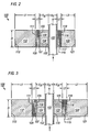
- FIG. 2 shows an elevational cross-section of one embodiment of an acoustic density cell 100 according to the present invention.
- the acoustic density cell 100 contains a delay line 104 of thickness X dl having opposing surfaces 103 and 105 .
- the surface 103 is in close acoustic contact with a fluid flowline 102 through which the formation fluid flows during the testing and collection of the formation fluid.
- the delay line 104 material may be a machineable glass or any other suitable material that would sufficiently delay the acoustic signal passing therethrough, preferably by a time that exceeds the transducer ringdown time, and have an acoustic impedance between the impedance of the piezoelectric material used in the transducer and the formation fluid.
- Such a delay line enables measuring the acoustic impedance of the fluid.
- An acoustic transducer 108 (transducer 1) of thickness L2 having a opposing surfaces 107 and 109 is placed against the delay line 104 .
- the transducer 108 may be used as an acoustic signal transmitter or a receiver.
- the transducer 108 preferably is made of a suitable piezoelectric material but is not limited to such a material.
- the surface 105 of the delay line 104 and the surface 107 of the transducer 108 are preferably bonded together.
- a backing 112 of thickness L 1 is placed against transducer 108 so that the surface 111 of the backing is in contact with the transducer 108 .
- the backing 112 is preferably made of a mixture of tungsten and a rubber material but is not limited to such a composition.
- the backing material 112 preferably has a high acoustic absorption coefficient and an acoustic impedance that will minimize the acoustic reflection from the surface 111 .
- the thickness L 1 is made sufficiently large so as to minimize reflections from the surface 113 .
- the surface 109 of the transducer 108 and the surface 111 of the backing 112 are preferably bonded together.
- a second acoustic transducer 116 (transducer 2) of thickness L 2 having opposing surfaces 115 and 117 is placed against the flowline 102 across from the delay line 104 .
- the transducer 116 also is preferably made of piezoelectric material but may be made of any other suitable material.
- the surface 115 of the transducer 116 is in close acoustic contact with the fluid flowline 102 .
- a backing 120 of thickness L 3 having opposing surfaces 119 and 121 is placed against the transducer.
- the surface 117 of the transducer 116 and the surface 119 of the backing 120 are preferably bonded together.
- the delay line 104 , first transducer 108 , backing 112 , second transducer 116 , and backing 120 preferably have the same depth D .
- FIG. 3 shows an elevational cross-section of an alternative embodiment of the sonic density cell 100 according to the present invention.
- the elements shown on the left of the fluid flowline 102 in FIG. 3 are identical to the elements shown in FIG. 2 .
- the elements to the right of the fluid flowline 102 in FIG. 3 are a mirror image of the elements to the left of the fluid flowline 102 .
- a delay line 124 of thickness X dl has a surface 123 in close acoustic contact with the fluid flowline 102 opposite the delay line 102 .
- a backing 120 of thickness L1 having surfaces 119 and 121 is placed against the transducer 116 .
- the surface 115 of the transducer 116 is preferably bonded to the surface 125 of the delay line 124 .
- the surface 117 of the transducer 116 and the surface 119 of the backing 120 are preferably bonded together.
- the advantages of this embodiment are that the transducers 108 and 116 are isolated from the fluid, the two sides of the sonic density cell are identical in design and the acoustic impedance of the fluid may be averaged for surfaces 103 and 123 .
- the overall size of the sonic density cell 100 is somewhat increased.
- the signal frequency applied to the transmitters may be varied from 0.3 to 10 mega hertz (MHz) depending on the materials used and the dimensions of the elements in constructing the sonic density cell 100 .
- MHz mega hertz
- the frequency of the signals transmitted through the fluid from one transducer to the other may be varied to obtain the viscosity of the fluid.
- viscosity and also scattering from the second phase in the continuous phase affect the frequency of signals passing through the fluid.
- the dimensions and signal frequencies indicated herein can be easily varied to suit different test scenarios and they are not intended as any limitations on the embodiment of the sonic density cell 100 .
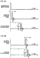
- FIG. 4A shows typical waveforms of input electrical signal, generated acoustic pressure wave, and received acoustic echo signal for the transmitter/receiver transducer 108 of FIG. 2 .
- an electrical signal of amplitude V 0 is applied to the transducer 108
- an acoustic pressure wave shown in FIG.4A is produced after a short time delay ( t 01 ).
- This acoustic pressure wave travels in all adjacent media. Whenever an acoustic wave encounters a new medium, a fraction of the wave amplitude is reflected and a fraction of the wave amplitude is transmitted through the new medium.
- the reflected wave from the interface of the delay line 104 and the test fluid flowing through the fluid flowline 102 provides a measure of the acoustic impedance of he fluid.
- the resultant echo signal of amplitude V pp1 is received by the transducer 108 at time t 1 .
- the time difference ( t 1 - t 01 ) is related to the speed of sound in the delay line 104 .
- the signal amplitude V pp1 of the echo is also related to the acoustic impedances of the material of the delay line 104 ( Z dl ) and that of the fluid interface ( Z fl ).
- the second transducer 116 detects its arrival at time t 2 with an amplitude V pp2 .
- a short time delay t 02 occurs between the arrival of the acoustic wave at the transducer 116 and the electronic detection of the signal.
- the time t 2 is related to the speed of sound through the delay line 104 and the speed of sound through the fluid path in the fluid flowline 102 .
- the amplitude V pp 2 of the signal received by the transducer 116 is related to the acoustic signal transmission and attenuation through the delay line 104 and through the fluid in the fluid flowline 102 .
- Physical properties of the delay line 104 material may be determined in the laboratory by known calibration procedures. Utilizing the acoustic density cell 100 measurements and the parameters of the properties of the delay line 104 , the density and compressibility of the test fluid may be determined using equations 1 through 14 given below. Also, acoustic attenuation coefficient ( ⁇ ) of the test fluid may be determined using the acoustic density cell 100 measurements and equations 15 through 18 given below.
- t 1 2 ⁇ ( t 01 + t dl )
- Z fl Z dl 1 + V pp 1 K 1 V O 1 - V pp 1 K 1 V O
- the fluid compressibility can now be determined from the density and sound speed:
- T dl-fl 2 ⁇ Z fl Z dl + Z fl
- T fl -2 2 ⁇ Z 2 Z fl + Z 2
- V pp 2 K 1 V 0 T dl-fl e (- ⁇ x fl ) ⁇ K 2 T fl- 2
- the acoustic attenuation coefficient ( ⁇ ) of a two phase fluid depends on the percentages of the two constituents. Acoustic attenuation coefficient of fluids containing known percentages of the two constituents can be determined in the laboratory. A graph plot of the laboratory measured acoustic attenuation coefficient as a function of the percentage of gas component in the fluid can be obtained. This acoustic attenuation depends on the viscosity, frequency and the size of the second phase in the continuous phase.
- FIG. 5 shows a typical plot of the acoustic attenuation coefficient ( ⁇ ) as a function of the percentage of gas phase content in a fluid when the other parameters remain constant.
- the fraction of the gas in the fluid ⁇ can be determined numerically by making a polynomial curve fit of the laboratory measured data to the plot in FIG. 5 . This polynomial fit is then compensated for the effects of viscosity and the second phase distribution. This compensation is preferably achieved by regression methods on known two-phase fluids.
- a typical formation is developed according to equation ( 19 ) given below.
- equation ( 19 ) given below.
- Equation 19 sibtracts viscosity effects to improve the accuracy of calculating ⁇ .
- the tool 24 is lowered into the wellbore 21 by means of the wireline 23' to a desired depth.
- the packer/probe 29 is urged against the wall of the wellbore 21 at the zone of interest in the formation 22 .
- the electro hydraulic system 25 deploys the probe of the packer/probe 29 and backup pads 27 to create a hydraulic seal with the elastomeric packer/probe 29 against the formation 22 .
- the pretest piston 30 is used to draw a small sample of fluid into the flowline 14 of the tool 24 while the flowline 14 is monitored using a high accuracy quartz pressure gauge 8 .
- the pressure in the flowline 14 increases until it equalizes with the pressure in the formation 22 . This is due to the formation 22 gradually releasing the fluids into the probe of the packer/probe 29 .
- the formation pressure is typically lower than the borehole 21 or hydrostatic pressure and this difference is used as a means for verifying that the packer/probe 29 is sealed against the wall of the borehole 21 .
- the fluids in the pore space of the formation 22 near the probe of the packer/probe 29 are typically invaded with the mud filtrate fluids.
- the area near the probe needs to be flushed or pumped until formation fluids are flowing into the tool 24 .
- the isolation valve 11 and the equalization valve 20 are opened, and the flushing pump 13 is started.
- the flushing pump 13 is preferably a double acting piston pump so that the fluid flow will be constant and as uniform as possible.
- this invention is not limited to a particular type of flushing pump and any suitable means may be used to serve the stated purpose.
- the flushing pump 13 draws fluid into the probe of the packer/probe 29 and expels fluid at hydrostatic pressure out of the equalization valve 20 .
- the pumping rate of the flushing pump 13 is regulated such that the pressure in the flowline 14 near the probe is maintained above the bubble point of the fluid sample.
- the sonic density cell 15 is used to measure the fluid properties.
- the sonic density cell 15 can monitor the density of the fluid, sound speed in the fluid, bulk modulus of the fluid, and presence of gas bubbles in the fluid. By monitoring the formation of gas bubbles in the fluid, the flow in the flowline 14 can be constantly adjusted so that a single phase fluid is maintained by regulating speed of the flushing pump 13 .
- the aforementioned fluid properties are of the type of fluid in the flowline 14 and knowledge of the fluid properties can be used to monitor the fluid flow while the formation fluid is being pumped for sample collection.
- the sample chamber valve 17 is opened and the equalization valve 20 is closed.
- the flushing pump 13 continues to pump the formation fluid through the flowline 14 and the fluid is directed into the sample chamber 18 until it is filled.
- the flushing pump 13 may continue to pressure the collected sample in the sample chamber 18 to a desired pressure level to assure in situ pressure level, and then all of the valves, the isolation valve 11 , the sample chamber valve 17 , and the equalization valve 20 are closed.
- the bubble point of the fluid in the flowline 14 is measured by using the sonic density cell 15 in conjunction with the flushing pump 13 .
- the flushing pump 13 is used to lower the pressure in the flowline 14 between the isolation valve 11 and the flushing pump 13 .
- the sonic density cell 15 determines the density change of the fluid and bubble formation in the flowline 14 .
- a pressure gauge (not shown) is also used to determine the bubble point of the fluid.
- FIG. 1B shows an alternative embodiment of the tool 24 wherein the packer/probe section 29 is near the bottom of the string of the sections in tool 24 for rathole type testing.
- FIG. 1C shows yet another embodiment of the tool 24 with an inflatable packer section of the packer/probe 29 rather than a single packer/probe unit. Additionally, multiple packer/probe sections can be used instead of a single packer/probe section 29 but the basic operation of the tool 24 remains the same.
- FIG. 6 shows a functional block diagram for recording signals from the sonic density cell 15 and other tool sections.
- the truck logging processor 240 contains a control unit 50 for controlling the operation of the tool 24 , a display monitor 52 for displaying the operator commands and the real time results from the tool 24 , and a recorder 54 that records desired signals to and from the tool 24 .
- a downhole microprocessor 200 (preprogrammed or operator controlled) instructs the signal input generator 210 to apply electrical signal shown in FIG 4A to transducer 1 108 .
- the echo signal received by transducer 108 after time t 1 and electrical signal generated by the transducer 116 after time t 2 are communicated to the downhole microprocessor 200 .
- the downhole microprocessor 200 computes the fluid density, the fluid compressibility, percentage of gas content in the test fluid and communicates the signals to signal processor 230 .
- Information received by the signal processor is communicated to the truck logging processor 240 where it processed, recorded and monitored by the testing personnel.
- the initial fluid drawn from the formation 22 typically contains mud filtrates which have invaded into the formation 22 . It is, therefore, important that the formation fluids collected downhole be uncontaminated (clean fluid) and in the same physical conditions in which such fluids are present in the formation. For example, the gas and oil contents of the fluid should be maintained in the manner present in the formation during the collection process. This requires determining when the fluid flowing through the flowline is substantially free of mud filtrates and collecting the fluid above the bubble point pressure of the fluid. As noted earlier, the prior art tools utilize resistivity measurements and optical means to continuously determine the downhole conditions of the fluid during the collection process and to control the flow rate to maintain the fluid pressure above the bubble point. Such apparatus and method are complex and are usually are very expensive, susceptible to contamination and very reliable. When a desired amount of the fluid has been collected in the fluid chamber 18 , a new command signal may be sent downhole to select other chambers or to stop the operation of the pump 17 or to reverse the cycle and start another cycle, if necessary.
- the formation fluid flow rate into the flowline 14 is slowly increased by controlling the flush-pump 13 while continuously monitoring the fluid density and the fluid compressibility.
- the gas in fluid if present, will expand into a gaseous state from its normal liquid state which it is present in the formation, which will be observed as a sudden decrease in the density.
- the pressure at which the density drops is the bubble point pressure of the fluid.
- the flow rate is decreased until the density suddenly rises to the initial value of the clean fluid and the corresponding fluid pressure. The procedure may be repeated if necessary to accurately determine the bubble point pressure.
Landscapes
- Physics & Mathematics (AREA)
- Life Sciences & Earth Sciences (AREA)
- Engineering & Computer Science (AREA)
- Chemical & Material Sciences (AREA)
- Health & Medical Sciences (AREA)
- Geology (AREA)
- Mining & Mineral Resources (AREA)
- General Physics & Mathematics (AREA)
- Pathology (AREA)
- Immunology (AREA)
- Acoustics & Sound (AREA)
- General Health & Medical Sciences (AREA)
- Biochemistry (AREA)
- Analytical Chemistry (AREA)
- Fluid Mechanics (AREA)
- Geochemistry & Mineralogy (AREA)
- General Life Sciences & Earth Sciences (AREA)
- Environmental & Geological Engineering (AREA)
- Oil, Petroleum & Natural Gas (AREA)
- Food Science & Technology (AREA)
- Medicinal Chemistry (AREA)
- General Chemical & Material Sciences (AREA)
- Chemical Kinetics & Catalysis (AREA)
- Geophysics (AREA)
- Investigating Or Analyzing Materials By The Use Of Ultrasonic Waves (AREA)
Priority Applications (2)
| Application Number | Priority Date | Filing Date | Title |
|---|---|---|---|
| DE69830475T DE69830475T2 (de) | 1998-04-01 | 1998-04-01 | Vorrichtung und Verfahren zur Untersuchung von Formationsflüssigkeiten in einem Bohrloch mittels akustischer Signale |
| EP98302530A EP0953726B1 (de) | 1998-04-01 | 1998-04-01 | Vorrichtung und Verfahren zur Untersuchung von Formationsflüssigkeiten in einem Bohrloch mittels akustischer Signale |
Applications Claiming Priority (1)
| Application Number | Priority Date | Filing Date | Title |
|---|---|---|---|
| EP98302530A EP0953726B1 (de) | 1998-04-01 | 1998-04-01 | Vorrichtung und Verfahren zur Untersuchung von Formationsflüssigkeiten in einem Bohrloch mittels akustischer Signale |
Publications (2)
| Publication Number | Publication Date |
|---|---|
| EP0953726A1 true EP0953726A1 (de) | 1999-11-03 |
| EP0953726B1 EP0953726B1 (de) | 2005-06-08 |
Family
ID=8234753
Family Applications (1)
| Application Number | Title | Priority Date | Filing Date |
|---|---|---|---|
| EP98302530A Expired - Lifetime EP0953726B1 (de) | 1998-04-01 | 1998-04-01 | Vorrichtung und Verfahren zur Untersuchung von Formationsflüssigkeiten in einem Bohrloch mittels akustischer Signale |
Country Status (2)
| Country | Link |
|---|---|
| EP (1) | EP0953726B1 (de) |
| DE (1) | DE69830475T2 (de) |
Cited By (11)
| Publication number | Priority date | Publication date | Assignee | Title |
|---|---|---|---|---|
| WO2005068994A1 (en) * | 2004-01-14 | 2005-07-28 | Baker Hughes Inc | METHOD AND APPARATUS FOR DETERMINING THE CONTAMINATION OF A DOWNHOLE FILTRATE FROM DENSITY MEASUREMENTS |
| WO2009048768A2 (en) * | 2007-10-09 | 2009-04-16 | Schlumberger Canada Limited | Modular connector and method |
| WO2009052235A1 (en) * | 2007-10-19 | 2009-04-23 | Schlumberger Canada Limited | Formation sampler with cleaning capability |
| US7886832B2 (en) | 2005-06-15 | 2011-02-15 | Schlumberger Technology Corporation | Modular connector and method |
| US7938199B2 (en) | 2006-06-09 | 2011-05-10 | Halliburton Energy Services, Inc. | Measurement while drilling tool with interconnect assembly |
| US8132621B2 (en) | 2006-11-20 | 2012-03-13 | Halliburton Energy Services, Inc. | Multi-zone formation evaluation systems and methods |
| CN105548354A (zh) * | 2015-11-27 | 2016-05-04 | 中国电建集团贵阳勘测设计研究院有限公司 | 一种在干孔中进行工程质量测试的装置 |
| US9574437B2 (en) | 2011-07-29 | 2017-02-21 | Baker Hughes Incorporated | Viscometer for downhole use |
| WO2017095447A1 (en) * | 2015-12-04 | 2017-06-08 | Halliburton Energy Services Inc. | Multipurpose permanent electromagnetic sensing system for monitoring wellbore fluids and formation fluids |
| GB2550862A (en) * | 2016-05-26 | 2017-12-06 | Metrol Tech Ltd | Method to manipulate a well |
| EP3066498A4 (de) * | 2013-11-05 | 2018-04-11 | Piezotech LLC | Flugzeit durch schlamm |
Citations (6)
| Publication number | Priority date | Publication date | Assignee | Title |
|---|---|---|---|---|
| US4571693A (en) * | 1983-03-09 | 1986-02-18 | Nl Industries, Inc. | Acoustic device for measuring fluid properties |
| US5335542A (en) * | 1991-09-17 | 1994-08-09 | Schlumberger Technology Corporation | Integrated permeability measurement and resistivity imaging tool |
| USRE34975E (en) * | 1990-05-16 | 1995-06-20 | Schlumberger Technology Corporation | Ultrasonic measurement apparatus |
| US5473939A (en) * | 1992-06-19 | 1995-12-12 | Western Atlas International, Inc. | Method and apparatus for pressure, volume, and temperature measurement and characterization of subsurface formations |
| US5583280A (en) * | 1995-01-26 | 1996-12-10 | Abbott Laboratories | Air bubble sensor with simplified mounting of piezo elements |
| US5635631A (en) * | 1992-06-19 | 1997-06-03 | Western Atlas International, Inc. | Determining fluid properties from pressure, volume and temperature measurements made by electric wireline formation testing tools |
-
1998
- 1998-04-01 DE DE69830475T patent/DE69830475T2/de not_active Expired - Lifetime
- 1998-04-01 EP EP98302530A patent/EP0953726B1/de not_active Expired - Lifetime
Patent Citations (6)
| Publication number | Priority date | Publication date | Assignee | Title |
|---|---|---|---|---|
| US4571693A (en) * | 1983-03-09 | 1986-02-18 | Nl Industries, Inc. | Acoustic device for measuring fluid properties |
| USRE34975E (en) * | 1990-05-16 | 1995-06-20 | Schlumberger Technology Corporation | Ultrasonic measurement apparatus |
| US5335542A (en) * | 1991-09-17 | 1994-08-09 | Schlumberger Technology Corporation | Integrated permeability measurement and resistivity imaging tool |
| US5473939A (en) * | 1992-06-19 | 1995-12-12 | Western Atlas International, Inc. | Method and apparatus for pressure, volume, and temperature measurement and characterization of subsurface formations |
| US5635631A (en) * | 1992-06-19 | 1997-06-03 | Western Atlas International, Inc. | Determining fluid properties from pressure, volume and temperature measurements made by electric wireline formation testing tools |
| US5583280A (en) * | 1995-01-26 | 1996-12-10 | Abbott Laboratories | Air bubble sensor with simplified mounting of piezo elements |
Cited By (23)
| Publication number | Priority date | Publication date | Assignee | Title |
|---|---|---|---|---|
| WO2005068994A1 (en) * | 2004-01-14 | 2005-07-28 | Baker Hughes Inc | METHOD AND APPARATUS FOR DETERMINING THE CONTAMINATION OF A DOWNHOLE FILTRATE FROM DENSITY MEASUREMENTS |
| US7913774B2 (en) | 2005-06-15 | 2011-03-29 | Schlumberger Technology Corporation | Modular connector and method |
| US9416655B2 (en) | 2005-06-15 | 2016-08-16 | Schlumberger Technology Corporation | Modular connector |
| US8931548B2 (en) | 2005-06-15 | 2015-01-13 | Schlumberger Technology Corporation | Modular connector and method |
| US7886832B2 (en) | 2005-06-15 | 2011-02-15 | Schlumberger Technology Corporation | Modular connector and method |
| EP2749732A1 (de) * | 2006-06-09 | 2014-07-02 | Halliburton Energy Services, Inc. | Messung während des Bohrens mithilfe einer Verbindungsanordnung |
| AU2007257804B2 (en) * | 2006-06-09 | 2012-11-15 | Halliburton Energy Services, Inc. | Measurement while drilling tool with interconnect assembly |
| NO343816B1 (no) * | 2006-06-09 | 2019-06-11 | Halliburton Energy Services Inc | Fremgangsmåte for prøvetaking av et formasjonsfluid |
| US7938199B2 (en) | 2006-06-09 | 2011-05-10 | Halliburton Energy Services, Inc. | Measurement while drilling tool with interconnect assembly |
| US9447664B2 (en) | 2006-11-20 | 2016-09-20 | Halliburton Energy Services, Inc. | Multi-zone formation evaluation systems and methods |
| US8132621B2 (en) | 2006-11-20 | 2012-03-13 | Halliburton Energy Services, Inc. | Multi-zone formation evaluation systems and methods |
| WO2009048768A3 (en) * | 2007-10-09 | 2009-06-04 | Schlumberger Ca Ltd | Modular connector and method |
| WO2009048768A2 (en) * | 2007-10-09 | 2009-04-16 | Schlumberger Canada Limited | Modular connector and method |
| RU2477364C2 (ru) * | 2007-10-09 | 2013-03-10 | Шлюмбергер Текнолоджи Б.В. | Модульное соединительное устройство и способ |
| WO2009052235A1 (en) * | 2007-10-19 | 2009-04-23 | Schlumberger Canada Limited | Formation sampler with cleaning capability |
| US9574437B2 (en) | 2011-07-29 | 2017-02-21 | Baker Hughes Incorporated | Viscometer for downhole use |
| EP3066498A4 (de) * | 2013-11-05 | 2018-04-11 | Piezotech LLC | Flugzeit durch schlamm |
| CN105548354A (zh) * | 2015-11-27 | 2016-05-04 | 中国电建集团贵阳勘测设计研究院有限公司 | 一种在干孔中进行工程质量测试的装置 |
| WO2017095447A1 (en) * | 2015-12-04 | 2017-06-08 | Halliburton Energy Services Inc. | Multipurpose permanent electromagnetic sensing system for monitoring wellbore fluids and formation fluids |
| US10591628B2 (en) | 2015-12-04 | 2020-03-17 | Halliburton Energy Services, Inc. | Multipurpose permanent electromagnetic sensing system for monitoring wellbore fluids and formation fluids |
| GB2550862A (en) * | 2016-05-26 | 2017-12-06 | Metrol Tech Ltd | Method to manipulate a well |
| GB2550862B (en) * | 2016-05-26 | 2020-02-05 | Metrol Tech Ltd | Method to manipulate a well |
| US11542783B2 (en) | 2016-05-26 | 2023-01-03 | Metrol Technology Limited | Method to manipulate a well using an underbalanced pressure container |
Also Published As
| Publication number | Publication date |
|---|---|
| EP0953726B1 (de) | 2005-06-08 |
| DE69830475D1 (de) | 2005-07-14 |
| DE69830475T2 (de) | 2005-11-03 |
Similar Documents
| Publication | Publication Date | Title |
|---|---|---|
| US5741962A (en) | Apparatus and method for analyzing a retrieving formation fluid utilizing acoustic measurements | |
| US5622223A (en) | Apparatus and method for retrieving formation fluid samples utilizing differential pressure measurements | |
| US5337821A (en) | Method and apparatus for the determination of formation fluid flow rates and reservoir deliverability | |
| US5934374A (en) | Formation tester with improved sample collection system | |
| EP1917417B1 (de) | Akustischer fluidanalysator | |
| US5230244A (en) | Formation flush pump system for use in a wireline formation test tool | |
| EP2404033B1 (de) | Frühe vorstosserkennung in einem öl- und gasbohrloch | |
| EP0697502B1 (de) | Bohrlochwerkzeug zur Bestimmung von Gesteinseigenschaften | |
| US4936139A (en) | Down hole method for determination of formation properties | |
| US6401538B1 (en) | Method and apparatus for acoustic fluid analysis | |
| US6128949A (en) | Phase change analysis in logging method | |
| EP1716314B1 (de) | Stufenlose absenkung für formationsdruckprüfung | |
| EP1623090B1 (de) | Formationsprüfvorrichtung und -verfahren zur optimierung von absenkung | |
| US8429962B2 (en) | Methods and apparatus to control a formation testing operation based on a mudcake leakage | |
| US7036362B2 (en) | Downhole determination of formation fluid properties | |
| US20040055745A1 (en) | Method and apparatus for combined NMR and formation testing for assessing relative permeability with formation testing and nuclear magnetic resonance testing | |
| US20020178805A1 (en) | Method and apparatus for downhole fluid characterization using flexural mechanical resonators | |
| US20020134587A1 (en) | Method, system and tool for reservoir evaluation and well testing during drilling operations | |
| US20120170406A1 (en) | Early Kick Detection in an Oil and Gas Well | |
| CN101454662A (zh) | 基于声学性质随压力的变化的井下流体表征 | |
| EP0953726B1 (de) | Vorrichtung und Verfahren zur Untersuchung von Formationsflüssigkeiten in einem Bohrloch mittels akustischer Signale | |
| US20080163680A1 (en) | Downhole fluid characterization based on changes in acoustic properties | |
| EP1397579B1 (de) | Verfahren, system und werkzeug zur lagerstättenbewertung und bohrlochuntersuchung bei bohrvorgängen | |
| US8919438B2 (en) | Detection and quantification of isolation defects in cement | |
| US7013723B2 (en) | Apparatus and methods for canceling the effects of fluid storage in downhole tools |
Legal Events
| Date | Code | Title | Description |
|---|---|---|---|
| PUAI | Public reference made under article 153(3) epc to a published international application that has entered the european phase |
Free format text: ORIGINAL CODE: 0009012 |
|
| AK | Designated contracting states |
Kind code of ref document: A1 Designated state(s): DE FR GB |
|
| AX | Request for extension of the european patent |
Free format text: AL;LT;LV;MK;RO;SI |
|
| 17P | Request for examination filed |
Effective date: 19991214 |
|
| AKX | Designation fees paid |
Free format text: DE FR GB |
|
| 17Q | First examination report despatched |
Effective date: 20040205 |
|
| GRAP | Despatch of communication of intention to grant a patent |
Free format text: ORIGINAL CODE: EPIDOSNIGR1 |
|
| GRAP | Despatch of communication of intention to grant a patent |
Free format text: ORIGINAL CODE: EPIDOSNIGR1 |
|
| GRAS | Grant fee paid |
Free format text: ORIGINAL CODE: EPIDOSNIGR3 |
|
| GRAA | (expected) grant |
Free format text: ORIGINAL CODE: 0009210 |
|
| AK | Designated contracting states |
Kind code of ref document: B1 Designated state(s): DE FR GB |
|
| REG | Reference to a national code |
Ref country code: GB Ref legal event code: FG4D |
|
| REF | Corresponds to: |
Ref document number: 69830475 Country of ref document: DE Date of ref document: 20050714 Kind code of ref document: P |
|
| ET | Fr: translation filed | ||
| PLBE | No opposition filed within time limit |
Free format text: ORIGINAL CODE: 0009261 |
|
| STAA | Information on the status of an ep patent application or granted ep patent |
Free format text: STATUS: NO OPPOSITION FILED WITHIN TIME LIMIT |
|
| 26N | No opposition filed |
Effective date: 20060309 |
|
| PGFP | Annual fee paid to national office [announced via postgrant information from national office to epo] |
Ref country code: GB Payment date: 20090312 Year of fee payment: 12 |
|
| GBPC | Gb: european patent ceased through non-payment of renewal fee |
Effective date: 20100401 |
|
| PG25 | Lapsed in a contracting state [announced via postgrant information from national office to epo] |
Ref country code: GB Free format text: LAPSE BECAUSE OF NON-PAYMENT OF DUE FEES Effective date: 20100401 |
|
| REG | Reference to a national code |
Ref country code: DE Ref legal event code: R082 Ref document number: 69830475 Country of ref document: DE Representative=s name: WEISSE, RENATE, DIPL.-PHYS. DR.-ING., DE |
|
| PGFP | Annual fee paid to national office [announced via postgrant information from national office to epo] |
Ref country code: FR Payment date: 20140328 Year of fee payment: 17 Ref country code: DE Payment date: 20140430 Year of fee payment: 17 |
|
| REG | Reference to a national code |
Ref country code: DE Ref legal event code: R119 Ref document number: 69830475 Country of ref document: DE |
|
| PG25 | Lapsed in a contracting state [announced via postgrant information from national office to epo] |
Ref country code: DE Free format text: LAPSE BECAUSE OF NON-PAYMENT OF DUE FEES Effective date: 20151103 |
|
| REG | Reference to a national code |
Ref country code: FR Ref legal event code: ST Effective date: 20151231 |
|
| PG25 | Lapsed in a contracting state [announced via postgrant information from national office to epo] |
Ref country code: FR Free format text: LAPSE BECAUSE OF NON-PAYMENT OF DUE FEES Effective date: 20150430 |