EP0953468B1 - Instrument panel with a reciprocable plunger - Google Patents
Instrument panel with a reciprocable plunger Download PDFInfo
- Publication number
- EP0953468B1 EP0953468B1 EP99302213A EP99302213A EP0953468B1 EP 0953468 B1 EP0953468 B1 EP 0953468B1 EP 99302213 A EP99302213 A EP 99302213A EP 99302213 A EP99302213 A EP 99302213A EP 0953468 B1 EP0953468 B1 EP 0953468B1
- Authority
- EP
- European Patent Office
- Prior art keywords
- plunger
- panel
- instrument panel
- collar
- radial projection
- Prior art date
- Legal status (The legal status is an assumption and is not a legal conclusion. Google has not performed a legal analysis and makes no representation as to the accuracy of the status listed.)
- Expired - Lifetime
Links
Images

Classifications
-
- B—PERFORMING OPERATIONS; TRANSPORTING
- B60—VEHICLES IN GENERAL
- B60K—ARRANGEMENT OR MOUNTING OF PROPULSION UNITS OR OF TRANSMISSIONS IN VEHICLES; ARRANGEMENT OR MOUNTING OF PLURAL DIVERSE PRIME-MOVERS IN VEHICLES; AUXILIARY DRIVES FOR VEHICLES; INSTRUMENTATION OR DASHBOARDS FOR VEHICLES; ARRANGEMENTS IN CONNECTION WITH COOLING, AIR INTAKE, GAS EXHAUST OR FUEL SUPPLY OF PROPULSION UNITS IN VEHICLES
- B60K35/00—Instruments specially adapted for vehicles; Arrangement of instruments in or on vehicles
- B60K35/10—Input arrangements, i.e. from user to vehicle, associated with vehicle functions or specially adapted therefor
-
- H—ELECTRICITY
- H01—ELECTRIC ELEMENTS
- H01H—ELECTRIC SWITCHES; RELAYS; SELECTORS; EMERGENCY PROTECTIVE DEVICES
- H01H2219/00—Legends
- H01H2219/054—Optical elements
- H01H2219/064—Optical isolation of switch sites
-
- H—ELECTRICITY
- H01—ELECTRIC ELEMENTS
- H01H—ELECTRIC SWITCHES; RELAYS; SELECTORS; EMERGENCY PROTECTIVE DEVICES
- H01H2221/00—Actuators
- H01H2221/036—Return force
- H01H2221/042—Foam
Definitions
- This invention relates to an illuminated instrument panel with a reciprocable plunger mounted through an aperture in the panel.
- the plunger can for example be used to re-set a function on the instrument panel, (e.g., the trip counter) but is not limited to any particular application.
- Objectives of the invention are to reduce light leakage where the plunger passes through the illuminated instrument panel, and to facilitate assembly of the plunger to the panel.
- the invention provides an illuminated instrument panel having a front face and a circuit board arranged behind and spaced from the front face, wherein a plunger is mounted in an aperture in the panel to operate a switch located on the circuit board, characterised in that: the aperture includes a collar extending from the rear face of the panel into the space behind the panel, the plunger having a head and a cylindrical rod-like part which has a cross-section adapted to be a close sliding fit in substantially the whole length of the collar so that the plunger is guided for reciprocating movement by the engagement between the collar and the rod-like part, the cylindrical rod-like part having a radial projection that extends beyond the internal diameter of the collar, the projection and/or the collar being resilient to allow the part of the plunger with the projection to be forced through the collar, and a compressible gasket mounted on the plunger between a shoulder on the plunger and the front face of the instrument panel, the thickness of the gasket being such that it is in contact with the shoulder and with the front of the panel when the radial projection
- the instrument panel is illuminated with illuminating light preferably travelling within the panel front face (which will then be of a transparent or translucent material with an opaque coverlay on the front surface) and/or travelling in a space behind the front panel.
- the radial projection can be tapered to ease insertion of the plunger through the aperture and to hinder removal.
- the rod-like part of the plunger can have a void section registering with the radial projection, arranged so that the resilient movement of the radial projection on insertion of the plunger into the aperture involves the temporary movement of part of the plunger into the void.
- Figure 1 shows an instrument panel 10 with an opaque coverlay 12 on the front.
- the coverlay prevents light from passing through the panel 10 (which will normally be translucent), except in places where the coverlay is cut away to allow transmission of light through for example the index marks around a speedometer dial and/or ideograms, letters, numbers or other markings which are to be illuminated.
- the coverlay is also cut away where a component has to pass through the panel, and this is the case at 14 in Figure 1.
- This circuit board carries an electronic switch 18.
- This can for example be of the type where a carbon pad mounted on a silicone rubber membrane is normally spaced from a set of contacts on the board, but can be pressed against the contacts to provide an electrical connection between the contacts. The resilience of the rubber membrane will ensure that the pad is moved away from the contacts to break the connection when the pressure is removed.
- Such switches are known in themselves.
- the switch 18 is to be operated by a plunger 20 which has a protruding knob at 22 and a shaft 24.
- the shaft 24 passes through a collar 26 formed integrally with the panel 10 and extending from the back of the panel.
- the shaft 24 has two diagonally opposite radial projections 28, and a through slot or void 30 in the region where the projections 28 are located.
- a foam rubber or foam plastic gasket 32 is fitted beneath a shoulder 34 of the knob 22.
- the plunger 20 is first offered up to the panel 10 in the position shown in Figure 2.
- the leading end of the shaft 24 is inserted in the collar 26 and pushed.
- the edges of the aperture in the panel 10 ride on the tapered outer surfaces of the projections 28.
- the projections 28 can collapse inwards as shown in Figure 3 on the application of pressure in the direction indicated by arrow A.
- the projections 28 Once the projections 28 have reached the end of the collar 26, they snap outwards as a result of the resilience of the material of the shaft 24, to take up the position shown in Figures 1 and 4. In this position the plunger is retained in the panel 10. It could possibly be removed by exerting a large withdrawal force on the knob 22, but the knob is smooth which will make it difficult to apply a large pulling force, and the faces of the projections 28 facing the knob 22 are steep, again to resist withdrawal.
- the user To operate the plunger, the user merely presses the head of the knob 22. This compresses the gasket 32 still further, until the tip of the shaft 24 operates the switch 18. Releasing the knob 22 then allows the stored energy in the foam gasket 32 to return the plunger to its start position, limited by the abutment of the radial projections 28 with the bottom of the sleeve 26.
- the gasket 32 both provides the necessary light seal and also the restoring force needed to return the knob 22 to its start position where the switch 18 is not being operated.
Landscapes
- Engineering & Computer Science (AREA)
- Chemical & Material Sciences (AREA)
- Combustion & Propulsion (AREA)
- Transportation (AREA)
- Mechanical Engineering (AREA)
- Push-Button Switches (AREA)
Description
- This invention relates to an illuminated instrument panel with a reciprocable plunger mounted through an aperture in the panel. The plunger can for example be used to re-set a function on the instrument panel, (e.g., the trip counter) but is not limited to any particular application.
- Objectives of the invention are to reduce light leakage where the plunger passes through the illuminated instrument panel, and to facilitate assembly of the plunger to the panel.
- It is known to mount a re-set knob behind the front face of an instrument panel with a return spring acting between a part of the knob and another fixed structure. This construction has to be assembled from behind the panel, which is disadvantageous. Also, it is difficult to prevent light leakage with such a construction.
- DE 3346296 (Siemens) discloses genetic panel with a switch construction in which a resilient cup biases a switch-operating button away from a panel through which it is mounted.
- The invention provides an illuminated instrument panel having a front face and a circuit board arranged behind and spaced from the front face, wherein a plunger is mounted in an aperture in the panel to operate a switch located on the circuit board, characterised in that: the aperture includes a collar extending from the rear face of the panel into the space behind the panel, the plunger having a head and a cylindrical rod-like part which has a cross-section adapted to be a close sliding fit in substantially the whole length of the collar so that the plunger is guided for reciprocating movement by the engagement between the collar and the rod-like part, the cylindrical rod-like part having a radial projection that extends beyond the internal diameter of the collar, the projection and/or the collar being resilient to allow the part of the plunger with the projection to be forced through the collar, and a compressible gasket mounted on the plunger between a shoulder on the plunger and the front face of the instrument panel, the thickness of the gasket being such that it is in contact with the shoulder and with the front of the panel when the radial projection abuts the rear of the panel, and provides a restoring force which opposes movement of the plunger shoulder towards the panel, whereby the switch can be operated by movement of the plunger towards the circuit board.
- The instrument panel is illuminated with illuminating light preferably travelling within the panel front face (which will then be of a transparent or translucent material with an opaque coverlay on the front surface) and/or travelling in a space behind the front panel.
- The use of a radial projection, which allows the plunger to be pushed through the aperture from the front of the panel, greatly assists assembly, in that the plunger can be assembled with the panel after other components have already been installed. Since the plunger only needs to be retained against a relatively low restoring force, this type of retention mechanism is satisfactory.
- Use of a compressible gasket, both to provide a light seal and to provide a restoring force when the plunger is pressed in, avoids the use of separate components to implement these two functions. The gasket is slightly compressed when the plunger is in its non-operated condition, and is compressed still further when the plunger is pressed.
- The radial projection can be tapered to ease insertion of the plunger through the aperture and to hinder removal. The rod-like part of the plunger can have a void section registering with the radial projection, arranged so that the resilient movement of the radial projection on insertion of the plunger into the aperture involves the temporary movement of part of the plunger into the void.
- The invention will now be further described, by way of example, with reference to the accompanying drawings in which:
- Figure 1
- is a cross section through an instrument panel, showing a plunger in accordance with the invention;
- Figure 2
- is an exploded view of the plunger and part of the instrument panel, prior to assembly;
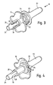
- Figure 3
- is a view corresponding to Figure 2, but showing an intermediate stage in assembly; and
- Figure 4
- shows the completed assembly.
- Figure 1 shows an
instrument panel 10 with anopaque coverlay 12 on the front. The coverlay prevents light from passing through the panel 10 (which will normally be translucent), except in places where the coverlay is cut away to allow transmission of light through for example the index marks around a speedometer dial and/or ideograms, letters, numbers or other markings which are to be illuminated. - The coverlay is also cut away where a component has to pass through the panel, and this is the case at 14 in Figure 1.
- Behind the
panel 12 there is a circuit board, apart 16 of which can be seen in Figure 1. This circuit board carries anelectronic switch 18. This can for example be of the type where a carbon pad mounted on a silicone rubber membrane is normally spaced from a set of contacts on the board, but can be pressed against the contacts to provide an electrical connection between the contacts. The resilience of the rubber membrane will ensure that the pad is moved away from the contacts to break the connection when the pressure is removed. Such switches are known in themselves. - The
switch 18 is to be operated by aplunger 20 which has a protruding knob at 22 and ashaft 24. Theshaft 24 passes through acollar 26 formed integrally with thepanel 10 and extending from the back of the panel. Theshaft 24 has two diagonally oppositeradial projections 28, and a through slot orvoid 30 in the region where theprojections 28 are located. - A foam rubber or foam
plastic gasket 32 is fitted beneath ashoulder 34 of theknob 22. - To fit the
plunger 20 in the instrument panel, the plunger is first offered up to thepanel 10 in the position shown in Figure 2. The leading end of theshaft 24 is inserted in thecollar 26 and pushed. The edges of the aperture in thepanel 10 ride on the tapered outer surfaces of theprojections 28. Because of thevoid 30 in the centre of theshaft 24, theprojections 28 can collapse inwards as shown in Figure 3 on the application of pressure in the direction indicated by arrow A. Once theprojections 28 have reached the end of thecollar 26, they snap outwards as a result of the resilience of the material of theshaft 24, to take up the position shown in Figures 1 and 4. In this position the plunger is retained in thepanel 10. It could possibly be removed by exerting a large withdrawal force on theknob 22, but the knob is smooth which will make it difficult to apply a large pulling force, and the faces of theprojections 28 facing theknob 22 are steep, again to resist withdrawal. - In the normal position, illustrated in Figure 1, the
foam gasket 32 is slightly compressed. This will ensure that a good light seal is made between the gasket and thecoverlay 12, so that no light will escape around theshaft 24 of the plunger. - To operate the plunger, the user merely presses the head of the
knob 22. This compresses thegasket 32 still further, until the tip of theshaft 24 operates theswitch 18. Releasing theknob 22 then allows the stored energy in thefoam gasket 32 to return the plunger to its start position, limited by the abutment of theradial projections 28 with the bottom of thesleeve 26. - It will be seen that the
gasket 32 both provides the necessary light seal and also the restoring force needed to return theknob 22 to its start position where theswitch 18 is not being operated. - Because all the assembly is carried out from the front of the instrument panel, the inclusion of the reset knob does not need to interfere with other stages of the instrument panel assembly.
Claims (7)
- An illuminated instrument panel (10) having a front face and a circuit board (16) arranged behind and spaced from the front face, wherein a plunger (20) is mounted in an aperture (14) in the panel to operate a switch (18) located on the circuit board (16), characterised in that: the aperture (14) includes a collar (26) extending from the rear face of the panel into the space behind the panel, the plunger having a head (22) and a cylindrical rod-like part (24) which has a cross-section adapted to be a sliding fit in substantially the whole length of the collar (26) so that the plunger (24) is guided for reciprocating movement by the engagement between the collar and the rod-like part (24), the cylindrical rod-like part (24) having a radial projection (28) that extends beyond the internal diameter of the collar (26), the projection (28) and/or the collar (26) being resilient to allow the part of the plunger with the projection (28) to be forced through the collar (26), and a compressible gasket (32) mounted on the plunger (20) between a shoulder (34) on the plunger and the front face of the instrument panel (10), the thickness of the gasket being such that it is in contact with the shoulder (34) and with the front of the panel (10) when the radial projection (28) abuts the rear of the panel, and provides a restoring force which opposes movement of the plunger shoulder towards the panel, whereby the switch (18) can be operated by movement of the plunger (20) towards the circuit board (16).
- An instrument panel as claimed in Claim 1, wherein the panel front face is of a transparent or translucent material with an opaque coverlay (12) on its front surface, and the illuminating light travels within the front face.
- An instrument panel as claimed in any preceding claim, wherein the gasket (32) is a foam gasket that is slightly compressed when the radial projection (28) abuts the rear of the panel.
- An instrument panel as claimed in Claim 3, wherein the radial projection (28) is tapered to ease insertion of the plunger through the aperture (14) and to hinder removal.
- An instrument panel as claimed in any preceding claim, wherein the radial projection (28) is tapered to ease insertion of the cylindrical rod-like part (24) of the plunger through the aperture and to hinder removal.
- An instrument panel as claimed in any preceding claim, wherein two diametrically opposite radial projections (28) are provided.
- An instrument panel as claimed in Claim 5 or Claim 6, wherein the rod-like part (24) of the plunger has a void section (30) registering with the radial projection (28) or projections, arranged so that the resilient movement of the radial projection (28) on insertion of the plunger into the aperture involves the temporary movement of the radial projection (28) into the void (30).
Applications Claiming Priority (2)
| Application Number | Priority Date | Filing Date | Title |
|---|---|---|---|
| GB9809499 | 1998-05-02 | ||
| GB9809499A GB2336817A (en) | 1998-05-02 | 1998-05-02 | Mounting reciprocable plunger in instrument panel |
Publications (3)
| Publication Number | Publication Date |
|---|---|
| EP0953468A2 EP0953468A2 (en) | 1999-11-03 |
| EP0953468A3 EP0953468A3 (en) | 2001-01-17 |
| EP0953468B1 true EP0953468B1 (en) | 2004-02-25 |
Family
ID=10831419
Family Applications (1)
| Application Number | Title | Priority Date | Filing Date |
|---|---|---|---|
| EP99302213A Expired - Lifetime EP0953468B1 (en) | 1998-05-02 | 1999-03-23 | Instrument panel with a reciprocable plunger |
Country Status (4)
| Country | Link |
|---|---|
| US (1) | US6176591B1 (en) |
| EP (1) | EP0953468B1 (en) |
| DE (1) | DE69914962D1 (en) |
| GB (1) | GB2336817A (en) |
Cited By (1)
| Publication number | Priority date | Publication date | Assignee | Title |
|---|---|---|---|---|
| DE102006038176A1 (en) * | 2006-08-14 | 2008-02-21 | Johnson Controls Automotive Electronics Gmbh | Switching device for use in instrument cluster of motor vehicle, has light source, light detector and light conductor provided for detection of switching status of device, where conductor is arranged between switching key and detector |
Families Citing this family (6)
| Publication number | Priority date | Publication date | Assignee | Title |
|---|---|---|---|---|
| FR2857501B1 (en) * | 2003-07-10 | 2005-09-16 | Siemens Vdo Automotive | RETROTECTIVE KEYBOARD, IN PARTICULAR KEYBOARD WITH JOINTIVE TOUCHES |
| JP2005308429A (en) * | 2004-04-19 | 2005-11-04 | Calsonic Kansei Corp | Display device |
| FR2967622B1 (en) * | 2010-11-22 | 2013-06-28 | Peugeot Citroen Automobiles Sa | COMBINED DASHBOARD OF A MOTOR VEHICLE |
| CA2837213C (en) * | 2011-06-27 | 2019-09-10 | Eaton Corporation | Integral module with lighted faceplate display |
| JP6525190B2 (en) * | 2015-03-09 | 2019-06-05 | 日本精機株式会社 | Display device |
| JP6872147B2 (en) * | 2017-06-29 | 2021-05-19 | 日本精機株式会社 | Instrument |
Family Cites Families (6)
| Publication number | Priority date | Publication date | Assignee | Title |
|---|---|---|---|---|
| GB2023937A (en) * | 1978-06-21 | 1980-01-03 | Itw Ltd | Electric push-button switches |
| DE3346296C2 (en) * | 1983-12-21 | 1994-05-19 | Siemens Ag | Actuator for transmitting a linear movement to a switch |
| US5171080A (en) * | 1991-05-28 | 1992-12-15 | Allied-Signal Inc. | Method of reducing light leakage from internally illuminated panels |
| IT231443Y1 (en) * | 1993-07-09 | 1999-08-03 | Veglia Borletti Srl | OPERATION BUTTON FOR A CONTROL ROD OF A MEASURING INSTRUMENT, FOR EXAMPLE A PARTIAL ODOMETER OF A MOTOR VEHICLE. |
| US5432684A (en) * | 1994-01-11 | 1995-07-11 | Delco Electronics Corp. | Process for manufacturing painted backlit displays having uniform backlighting intensity |
| US5631881A (en) * | 1996-05-01 | 1997-05-20 | Timex Corporation | Push button assembly for an electronic wrist instrument |
-
1998
- 1998-05-02 GB GB9809499A patent/GB2336817A/en not_active Withdrawn
-
1999
- 1999-03-23 EP EP99302213A patent/EP0953468B1/en not_active Expired - Lifetime
- 1999-03-23 DE DE69914962T patent/DE69914962D1/en not_active Expired - Lifetime
- 1999-05-03 US US09/304,476 patent/US6176591B1/en not_active Expired - Fee Related
Cited By (1)
| Publication number | Priority date | Publication date | Assignee | Title |
|---|---|---|---|---|
| DE102006038176A1 (en) * | 2006-08-14 | 2008-02-21 | Johnson Controls Automotive Electronics Gmbh | Switching device for use in instrument cluster of motor vehicle, has light source, light detector and light conductor provided for detection of switching status of device, where conductor is arranged between switching key and detector |
Also Published As
| Publication number | Publication date |
|---|---|
| GB2336817A (en) | 1999-11-03 |
| EP0953468A2 (en) | 1999-11-03 |
| US6176591B1 (en) | 2001-01-23 |
| DE69914962D1 (en) | 2004-04-01 |
| EP0953468A3 (en) | 2001-01-17 |
| GB9809499D0 (en) | 1998-07-01 |
Similar Documents
| Publication | Publication Date | Title |
|---|---|---|
| US4885443A (en) | Sealed backlit switch assembly | |
| GB1603913A (en) | Pushbutton control device for switching an elelctronic or electric circuit | |
| EP1387373A3 (en) | Push-button switch, and operating device and teaching pendant comprising the same | |
| GB2276767A (en) | Selectively illuminated indicator | |
| US6176591B1 (en) | Instrument panel with a reciprocable plunger | |
| EP1139359B1 (en) | Switch device and method of assembling switch device | |
| US4277665A (en) | Illuminated push-button electrical switch | |
| EP0896349A3 (en) | Cover member for illuminated push button switch and method for manufacturing same | |
| US5430267A (en) | Keyboard switch | |
| CA1226319A (en) | Push button for electrical switch | |
| GB2255232A (en) | Alarm call points | |
| EP0834847A1 (en) | Electrical equipment for anti-theft installations or similar | |
| KR100411552B1 (en) | Elevator push button | |
| FI65684B (en) | ELEKTRISK DRIFTSKOPPLING | |
| KR100285522B1 (en) | Structure of Electronic Control Switch | |
| JPS584411B2 (en) | Push button switch with lamp display | |
| ATE395535T1 (en) | GEAR LEVER MECHANISM | |
| JPH082895Y2 (en) | Switch device | |
| JP2537854B2 (en) | Push button device | |
| JP3018207U (en) | Optical rotary encoder with push button switch | |
| JPH06243754A (en) | Push button switch | |
| JPS5826427Y2 (en) | Self-illuminated push button key | |
| FR2438294A2 (en) | Opto-electronic touch switch with luminous indication - uses opaque plate adjacent to transparent plate behind light screen to prevent light escape | |
| KR930007693Y1 (en) | Switch | |
| KR0146429B1 (en) | Knob operation structure of car audio |
Legal Events
| Date | Code | Title | Description |
|---|---|---|---|
| PUAI | Public reference made under article 153(3) epc to a published international application that has entered the european phase |
Free format text: ORIGINAL CODE: 0009012 |
|
| AK | Designated contracting states |
Kind code of ref document: A2 Designated state(s): DE FR GB |
|
| AX | Request for extension of the european patent |
Free format text: AL;LT;LV;MK;RO;SI |
|
| PUAL | Search report despatched |
Free format text: ORIGINAL CODE: 0009013 |
|
| AK | Designated contracting states |
Kind code of ref document: A3 Designated state(s): AT BE CH CY DE DK ES FI FR GB GR IE IT LI LU MC NL PT SE |
|
| AX | Request for extension of the european patent |
Free format text: AL;LT;LV;MK;RO;SI |
|
| 17P | Request for examination filed |
Effective date: 20010618 |
|
| AKX | Designation fees paid |
Free format text: DE FR GB |
|
| 17Q | First examination report despatched |
Effective date: 20020903 |
|
| GRAP | Despatch of communication of intention to grant a patent |
Free format text: ORIGINAL CODE: EPIDOSNIGR1 |
|
| GRAS | Grant fee paid |
Free format text: ORIGINAL CODE: EPIDOSNIGR3 |
|
| GRAA | (expected) grant |
Free format text: ORIGINAL CODE: 0009210 |
|
| AK | Designated contracting states |
Kind code of ref document: B1 Designated state(s): DE FR GB |
|
| PG25 | Lapsed in a contracting state [announced via postgrant information from national office to epo] |
Ref country code: FR Free format text: LAPSE BECAUSE OF FAILURE TO SUBMIT A TRANSLATION OF THE DESCRIPTION OR TO PAY THE FEE WITHIN THE PRESCRIBED TIME-LIMIT Effective date: 20040225 |
|
| REG | Reference to a national code |
Ref country code: GB Ref legal event code: FG4D |
|
| REF | Corresponds to: |
Ref document number: 69914962 Country of ref document: DE Date of ref document: 20040401 Kind code of ref document: P |
|
| PG25 | Lapsed in a contracting state [announced via postgrant information from national office to epo] |
Ref country code: GB Free format text: LAPSE BECAUSE OF NON-PAYMENT OF DUE FEES Effective date: 20040525 |
|
| PG25 | Lapsed in a contracting state [announced via postgrant information from national office to epo] |
Ref country code: DE Free format text: LAPSE BECAUSE OF FAILURE TO SUBMIT A TRANSLATION OF THE DESCRIPTION OR TO PAY THE FEE WITHIN THE PRESCRIBED TIME-LIMIT Effective date: 20040526 |
|
| PLBE | No opposition filed within time limit |
Free format text: ORIGINAL CODE: 0009261 |
|
| STAA | Information on the status of an ep patent application or granted ep patent |
Free format text: STATUS: NO OPPOSITION FILED WITHIN TIME LIMIT |
|
| GBPC | Gb: european patent ceased through non-payment of renewal fee |
Effective date: 20040525 |
|
| EN | Fr: translation not filed | ||
| 26N | No opposition filed |
Effective date: 20041126 |