EP0953253B1 - Motion-compensated predictive image encoding and decoding - Google Patents
Motion-compensated predictive image encoding and decoding Download PDFInfo
- Publication number
- EP0953253B1 EP0953253B1 EP98946664A EP98946664A EP0953253B1 EP 0953253 B1 EP0953253 B1 EP 0953253B1 EP 98946664 A EP98946664 A EP 98946664A EP 98946664 A EP98946664 A EP 98946664A EP 0953253 B1 EP0953253 B1 EP 0953253B1
- Authority
- EP
- European Patent Office
- Prior art keywords
- motion
- frame
- decoding
- compensated
- motion vectors
- Prior art date
- Legal status (The legal status is an assumption and is not a legal conclusion. Google has not performed a legal analysis and makes no representation as to the accuracy of the status listed.)
- Expired - Lifetime
Links
Images

Classifications
-
- H—ELECTRICITY
- H04—ELECTRIC COMMUNICATION TECHNIQUE
- H04N—PICTORIAL COMMUNICATION, e.g. TELEVISION
- H04N19/00—Methods or arrangements for coding, decoding, compressing or decompressing digital video signals
- H04N19/50—Methods or arrangements for coding, decoding, compressing or decompressing digital video signals using predictive coding
- H04N19/503—Methods or arrangements for coding, decoding, compressing or decompressing digital video signals using predictive coding involving temporal prediction
- H04N19/51—Motion estimation or motion compensation
- H04N19/513—Processing of motion vectors
- H04N19/517—Processing of motion vectors by encoding
-
- H—ELECTRICITY
- H04—ELECTRIC COMMUNICATION TECHNIQUE
- H04N—PICTORIAL COMMUNICATION, e.g. TELEVISION
- H04N19/00—Methods or arrangements for coding, decoding, compressing or decompressing digital video signals
- H04N19/50—Methods or arrangements for coding, decoding, compressing or decompressing digital video signals using predictive coding
- H04N19/587—Methods or arrangements for coding, decoding, compressing or decompressing digital video signals using predictive coding involving temporal sub-sampling or interpolation, e.g. decimation or subsequent interpolation of pictures in a video sequence
Definitions
- the invention relates to a method of motion-compensated predictively encoding and decoding, image signals according to the preamble of the claims 1 and 3, respectively.
- the invention also relates to a device for motion -compensated predictively decoding image signals according to the preamble of claim 6.
- Such a encoding and decoding method and such a device are known from JP-A-9284777.
- the H.263 standard for low bit-rate video-conferencing [1]-[2] is based on a video compression procedure which exploits the high degree of spatial and temporal correlation in natural video sequences.
- the hybrid DPCM/DCT coding removes temporal redundancy using inter-frame motion compensation.
- the residual error images are further processed by block Discrete Cosine Transform (DCT), which reduces spatial redundancy by de-correlating the pixels within a block, and concentrates the energy of the block itself into a few low order coefficients.
- DCT coefficients are then quantized according to a fixed quantization matrix that is scaled by a Scalar Quantization factor (SQ).
- SQ Scalar Quantization factor
- VLC Variable Length Coding
- the H.263 coding standard defines the techniques to be used and the syntax of the bit-stream. There are some degrees of freedom in the design of the encoder. The standard puts no constraints about important processing stages such as motion estimation, adaptive scalar quantization, and bit-rate control.
- JP-A-9284777 discloses a method for improving the motion compensation of the motion picture coding at a low rate by eliminating the need to transmit motion vectors.
- Motion compensated pictures can be obtained by interpolating the same set of motion vectors obtained at the encoder and decoder, based on their position from the reference frame picture. Only the difference between the motion compensated pictures and the source pictures are transmitted to the decoder.
- Motion vectors for the frame pictures are obtained by interpolating the motion vector between the reference frame picture and a predicted frame picture.
- a first aspect of he invention provides an encoding method as defined in the characterizing part of claim 1.
- a second aspect of the invention provides a decoding method and device as defined in claims 3 and 6. Further aspects of the invention provide a multimedia apparatus (claim 7) and a display apparatus (claim 8). Advantageous embodiments are defined in the dependent claims.
- an input video signal IV is applied to a frame skipping unit 1.
- An output of the frame skipping unit 1 is connected to a non-inverting input of a sub tracer 3 and to a first input of a change-over switch 7.
- the output of the frame skipping unit 1 further supplies a current image signal to a temporal prediction unit 5.
- An inverting input of the sub tracer 3 is connected to an output of the temporal prediction unit 5.
- a second input of the change-over switch 7 is connected to an output of the sub tracer 3.
- An output of the change-over switch 7 is connected to a cascade arrangement of a Discrete Cosine Transformation encoder DCT and a quantizing unit Q.
- An out of the quantizing unit Q is connected to an input of a variable length encoder VLC, an output of which is connected to a buffer unit BUF that supplies an output bit-stream OB.
- the output of the quantizing unit Q is also connected to a cascade arrangement of a de-quantizing unit Q -1 and a DCT decoder DCT -1 .
- An output of the DCT decoder DCT -1 is coupled to a first input of an adder 9, a second input of which is coupled to the output of the temporal prediction unit 5 thru a switch 11.
- An output of the adder 9 supplies a reconstructed previous image to the temporal prediction unit 5.
- the temporal prediction unit 5 calculates motion vectors MV which are also encoded by the variable length encoder VLC.
- the buffer unit BUF supplies a control signal to the quantizing unit Q, and to a coding selection unit 13 which supplies an Intra-frame / Predictive encoding control signal I/P to the switches 7 and 11. If intra-frame encoding is carried out, the switches 7, 11 are in the positions shown in Fig. 1.
- the temporal prediction unit 5 includes a motion estimator ME and a motion-compensated interpolator MCI which both receive the current image from the frame skipping unit 1 and the reconstructed previous image from the adder 9.
- the motion vectors MV calculated by the motion estimator ME are applied to the motion-compensated interpolator MCI and to the variable length encoder VLC.
- NO-MV H.263 low bit-rate video encoders and decoders, where almost no information is transmitted about the motion vectors.
- the NO-MV method is based on the possibility that the video decoder can calculate its own motion vectors, or can predict the motion vectors starting from an initial motion information received from the encoder. Even if the method should be quite independent on the motion estimation strategy, we will present it jointly to our new motion estimator, since we think that the best performances will be achieved when the two techniques are used together.
- the H.263 video compression is based on an inter-frame DPCM/DCT encoding loop: there is a motion compensated prediction from a previous image to the current one and the prediction error is DCT encoded. At least one frame is a reference frame, encoded without temporal prediction.
- the basic H.263 standard has two types of pictures: I-pictures that are strictly intra-frame encoded, and P-pictures that are temporally predicted from earlier frames.
- a macro-block is composed by four luminance (Y) blocks, covering a 16 16 area in a picture, and two chrominance blocks (U and V), due to the lower chrominance resolution.
- a block is the elementary unit over which DCT operates, it consists of 88 pixels.
- the coarseness of quantization is defined by a quantization parameter for the first three layers and a fixed quantization matrix which sets the relative coarseness of quantization for each coefficient.
- Frame skipping is also used as a necessary way to reduce the bit-rate while keeping an acceptable picture quality. As the number of skipped frames is normally variable and depends on the output buffer fullness, the buffer regulation should be related in some way to frame skipping and quantizer step size variations.
- one motion vector per MB is assigned.
- the motion estimation strategy is not specified, but the motion vectors range is fixed to [-16, + 15.5] pixels in a picture for both components. This range can be extended to [-31.5, +31.5] when certain options are used. Every macro-block vector (MV) is then differentially encoded with a proper VLC.
- MV macro-block vector
- the motion estimation plays a fundamental role in the encoding process, since the quality of temporally predicted pictures strongly depends on the motion vectors accuracy and reliability.
- the temporal prediction block diagram is shown in Fig. 2.
- the similar block has a center which is shifted with respect to b ⁇ c over the motion vector d ⁇ ( b ⁇ c , t ).
- d ⁇ (b ⁇ c ,t) a number of candidate vectors C ⁇ are evaluated applying an error measure e ( C ⁇ , b ⁇ c ,t )to quantify block similarity.
- the candidate set consists of spatial and spatio-temporal prediction vectors from a 3-D neighborhood and an updated prediction vector. This implicitly assumes spatial and/or temporal consistency.
- the updating process involves updates added to either of the spatial predictions.
- the error function is a cost function of the luminance values, I( x ⁇ ,t ), and those of the shifted block from the previous field, I(x ⁇ -C ⁇ ,t-T ) , summed over the block B(b ⁇ c ) .
- a common choice, which we also use, is the Sum of the Absolute Differences (SAD).
- I ( x ⁇ , t ) ⁇ I ( x ⁇ ⁇ C ⁇ , t ⁇ T )
- the estimation process is iterated several times, using the motion vectors calculated in the previous iteration to initialize the current iteration, as temporal candidate vectors.
- both previous and current images are scanned from top to bottom and from left to right, that is in the "normal video” scanning direction.
- the second and fourth iteration are executed with both the images scanned in "anti-video" direction, from bottom to top and from right to left.
- first and second iteration are applied on pre-filtered copies of the two decoded images and without sub-pixel accuracy, while the third and fourth iteration are done directly on the original (decoded) images and produce a half-pixel accurate motion vectors.
- I(x, y, t) is the luminance value of the current pixel
- Ipf (x, y, t) is the correspondent filtered version
- div is the integer division.
- the median interpolation acts separately on the horizontal and vertical components of the motion vectors. From one iteration to the following we change the subsampling grid in order to refine the vectors that were interpolated in the previous iteration.
- the matching error is calculated on blocks of sizes 2X and 2Y, but the best vector is assigned to smaller blocks with dimensions X and Y. This feature is called block overlapping, because the larger 2X 2Y block overlaps the final X ⁇ Y block in horizontal and vertical direction. It contributes to improve the coherence and reliability of the motion vector field.
- This new block matching motion estimator can calculate the object's true motion with great accuracy, yielding a very coherent motion vector field, from the spatial and temporal points of view. This means that the VLC differential encoding of macro-block vectors should achieve lower bit-rates in comparison with vectors estimated from "classical" full-search block matchers.
- the amount of motion vector bits saved can be used to reduce the transmission channel capacity, without depreciating the image quality, or to allow a less coarse DCT coefficients quantization, thus considerably improving the image quality.
- the method requires a motion estimator, or a similar processing module, also in the video decoding terminal.
- high-quality, low-cost motion estimators available on the market, such as the one we presented above.
- the temporal resolution quality remains almost unchanged, because of: 1) the good performances of the motion estimation stages used by both encoding and decoding terminals, and 2) the temporal consistency of motion, which allows in most cases a good prediction even if the previous motion vector field is used instead of the actual one. All errors in this assumption can be repaired by the encoder, for example, by predictive coding on the vector field.
- Fig. 3 shows a decoder in accordance with the present invention.
- An incoming bit-stream is applied to a buffer BUFF having an output which is coupled to an input of a variable length decoder VLC -1 .
- the variable length decoder VLC -1 supplies image data to a cascade arrangement of an inverse quantizer Q -1 and a DCT decoder DCT -1 .
- An output of the DCT decoder DCT -1 is coupled to a first input of an adder 15, an output of which supplies the output signal of the decoder.
- the variable length decoder VLC -1 further supplies motion vectors MV for the first predictively encoded frame.
- the motion vectors are applied to a motion-compensation unit MC which receives the output signal of the decoder.
- An output signal of the motion-compensation unit MC is applied to a second input of the adder 15 thru a switch 17 which is controlled by an Intra-frame / Predictive encoding control signal I/P from the variable length decoder VLC -1 .
- the decoder comprises its own motion vector estimator ME2 which calculates motion vectors in dependence on the output signal of the decoder and a delayed version of that output signal supplied by a frame delay FM.
- the switch 19 applies the motion vectors from the variable length decoder VLC -1 or the motion vectors from the motion estimator ME2 to the motion-compensation unit MC.
- the switch 19 is controlled by the control signal I/P delayed over a frame delay by means of a delay unit ⁇ .
- Fig. 4 shows a image signal reception device in accordance with the present invention.
- Parts (T, Fig. 3, VSP) of this device may be part of a multi-media apparatus.
- a satellite dish SD receives a motion-compensated predictively encoded image signal in accordance with the present invention.
- the received signal is applied to a tuner T, the output signal of which is applied to the decoder of Fig. 3.
- the decoded output signal of the decoder of Fig. 3 is subjected to normal video signal processing operations VSP, the result of which is displayed on a display D.
- a primary aspect of the invention relates to a low bit-rate video coding method fully compatible with present standards, such as the H.263 standard.
- the motion vector information is encoded and transmitted only one time, together with the first P-frame following an I-frame (the first images pair of a sequence). Until the next I-frame, the motion vectors calculated during an images pair and properly stored in a memory buffer are applied for the temporal prediction during the subsequent images pair, and so on. This procedure re-starts in presence of a new I-frame.
- Both the encoding and decoding terminals calculate their own motion vectors and store them in a proper local memory buffer. It can be used at CIF (352 pixels by 288 lines), QCIF (176 pixels by 144 lines), and SQCIF (128 pixels per 96 lines) resolution.
- a method and an apparatus for H.263 low bit-rate video encoding and decoding stages which allow a reduction of the total bit-rate, since the motion vector information is transmitted only during the first P-frame following an 1-frame.
- the picture quality is very similar to the one achievable by the standard H.263 approach.
- a method and an apparatus for H.263 low bit-rate video encoding and decoding stages which allow a consistent improving of the image quality when compared to the standard H.263 approach, while the target bit-rate remains very similar.
- a method and an apparatus which use a memory buffer, placed in the motion estimation stage of the temporal prediction loop of the H.263 video encoder, to store the motion vectors related to an images pair. Such vectors will be used for the temporal prediction of the subsequent images pair.
- a method and an apparatus which use a memory buffer and a motion estimation stage, placed in the H.263 video decoder.
- the memory buffer is necessary to store the motion vectors calculated from the motion estimation stage. They are related to a certain images pair and will be used for the temporal prediction of the subsequent images pair.
- a method and an apparatus in which the decision to send the motion vectors information only during the first P-frame following an I-frame is taken from the "INTRA/INTER coding selection" module (see Fig. 1) of the video encoder.
- an encoded signal comprises:
- an encoded signal comprises:
- the supplying step covers both supplying to a transmission medium and supplying to a storage medium.
- a receiving step covers both receiving from a transmission medium and receiving from a storage medium.
- the invention can be implemented by means of hardware comprising several distinct elements, and by means of a suitably programmed computer. In the device claim enumerating several means, several of these means can be embodied by one and the same item of hardware.
Landscapes
- Engineering & Computer Science (AREA)
- Multimedia (AREA)
- Signal Processing (AREA)
- Compression Or Coding Systems Of Tv Signals (AREA)
Description
- The invention relates to a method of motion-compensated predictively encoding and decoding, image signals according to the preamble of the
claims - The invention also relates to a device for motion -compensated predictively decoding image signals according to the preamble of claim 6.
- Such a encoding and decoding method and such a device are known from JP-A-9284777.
- The H.263 standard for low bit-rate video-conferencing [1]-[2] is based on a video compression procedure which exploits the high degree of spatial and temporal correlation in natural video sequences. The hybrid DPCM/DCT coding removes temporal redundancy using inter-frame motion compensation. The residual error images are further processed by block Discrete Cosine Transform (DCT), which reduces spatial redundancy by de-correlating the pixels within a block, and concentrates the energy of the block itself into a few low order coefficients. The DCT coefficients are then quantized according to a fixed quantization matrix that is scaled by a Scalar Quantization factor (SQ). Finally, Variable Length Coding (VLC) achieves high encoding efficiency and produces a bit-stream, which is transmitted over ISDN (digital) or PSTN (analog) channels, at constant bit-rates. Due to the intrinsic structure of H.263, the final bit-stream is produced at variable bit-rate, hence it has to be transformed to constant bit-rate by the insertion of an output buffer which acts as feedback controller. The buffer controller has to achieve a target bit-rate with consistent visual quality, low delay and low complexity. It monitors the amount of bits produced and dynamically adjusts the quantization parameters, according to its fullness status and to the image complexity.
- The H.263 coding standard defines the techniques to be used and the syntax of the bit-stream. There are some degrees of freedom in the design of the encoder. The standard puts no constraints about important processing stages such as motion estimation, adaptive scalar quantization, and bit-rate control.
- JP-A-9284777 discloses a method for improving the motion compensation of the motion picture coding at a low rate by eliminating the need to transmit motion vectors. Motion compensated pictures can be obtained by interpolating the same set of motion vectors obtained at the encoder and decoder, based on their position from the reference frame picture. Only the difference between the motion compensated pictures and the source pictures are transmitted to the decoder. Motion vectors for the frame pictures are obtained by interpolating the motion vector between the reference frame picture and a predicted frame picture.
- It is inter alia, an object of the invention to improve the known motion compensated predictive image encoding and decoding techniques. To this end, a first aspect of he invention provides an encoding method as defined in the characterizing part of
claim 1. A second aspect of the invention provides a decoding method and device as defined inclaims 3 and 6. Further aspects of the invention provide a multimedia apparatus (claim 7) and a display apparatus (claim 8). Advantageous embodiments are defined in the dependent claims. - These and other aspects of the invention will be apparent from and elucidated with reference to the embodiments described hereinafter.
- In the drawings:
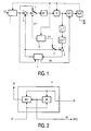
- Fig. 1 shows a basic DPCM/DCT video compression block diagram in accordance with the present invention;
- Fig. 2 shows a temporal prediction unit in accordance with the present invention;
- Fig. 3 shows a decoder block diagram in accordance with the present invention; and
- Fig. 4 shows a image signal detection device in accordance with the present invention.
- In the image encoder of Fig. 1, an input video signal IV is applied to a
frame skipping unit 1. An output of theframe skipping unit 1 is connected to a non-inverting input of asub tracer 3 and to a first input of a change-over switch 7.The output of theframe skipping unit 1 further supplies a current image signal to atemporal prediction unit 5. An inverting input of thesub tracer 3 is connected to an output of thetemporal prediction unit 5. A second input of the change-over switch 7 is connected to an output of thesub tracer 3. An output of the change-over switch 7 is connected to a cascade arrangement of a Discrete Cosine Transformation encoder DCT and a quantizing unit Q. An out of the quantizing unit Q is connected to an input of a variable length encoder VLC, an output of which is connected to a buffer unit BUF that supplies an output bit-stream OB. - The output of the quantizing unit Q is also connected to a cascade arrangement of a de-quantizing unit Q-1 and a DCT decoder DCT-1. An output of the DCT decoder DCT-1 is coupled to a first input of an
adder 9, a second input of which is coupled to the output of thetemporal prediction unit 5 thru aswitch 11. An output of theadder 9 supplies a reconstructed previous image to thetemporal prediction unit 5. Thetemporal prediction unit 5 calculates motion vectors MV which are also encoded by the variable length encoder VLC. The buffer unit BUF supplies a control signal to the quantizing unit Q, and to acoding selection unit 13 which supplies an Intra-frame / Predictive encoding control signal I/P to theswitches switches - As shown in Fig. 2, the
temporal prediction unit 5 includes a motion estimator ME and a motion-compensated interpolator MCI which both receive the current image from theframe skipping unit 1 and the reconstructed previous image from theadder 9. The motion vectors MV calculated by the motion estimator ME are applied to the motion-compensated interpolator MCI and to the variable length encoder VLC. - In this disclosure we introduce a new method for H.263 low bit-rate video encoders and decoders, where almost no information is transmitted about the motion vectors (NO-MV). The NO-MV method is based on the possibility that the video decoder can calculate its own motion vectors, or can predict the motion vectors starting from an initial motion information received from the encoder. Even if the method should be quite independent on the motion estimation strategy, we will present it jointly to our new motion estimator, since we think that the best performances will be achieved when the two techniques are used together.
- Thanks to our approach, we achieve a superior image quality compared to "classical" H.263 standard video terminals, without increasing the final bit-rate. In fact the bit-budget required to encode and transmit the motion information can be saved and re-used for a finer quantization of DCT coefficients, thus yielding a better spatial resolution (sharpness) pictures. On the other hand, it is also possible to maintain the typical H.263 image quality while decreasing the final bit-rate, due to no motion information transmission, thus increasing the channel efficiency.
- As shown in Fig. 1, the H.263 video compression is based on an inter-frame DPCM/DCT encoding loop: there is a motion compensated prediction from a previous image to the current one and the prediction error is DCT encoded. At least one frame is a reference frame, encoded without temporal prediction. Hence the basic H.263 standard has two types of pictures: I-pictures that are strictly intra-frame encoded, and P-pictures that are temporally predicted from earlier frames.
- The basic H.263 motion estimation and compensation stages operate on macroblocks. A macro-block (MB) is composed by four luminance (Y) blocks, covering a 16 16 area in a picture, and two chrominance blocks (U and V), due to the lower chrominance resolution. A block is the elementary unit over which DCT operates, it consists of 88 pixels. The coarseness of quantization is defined by a quantization parameter for the first three layers and a fixed quantization matrix which sets the relative coarseness of quantization for each coefficient. Frame skipping is also used as a necessary way to reduce the bit-rate while keeping an acceptable picture quality. As the number of skipped frames is normally variable and depends on the output buffer fullness, the buffer regulation should be related in some way to frame skipping and quantizer step size variations.
- In the H.263 main profile, one motion vector per MB is assigned. The motion estimation strategy is not specified, but the motion vectors range is fixed to [-16, + 15.5] pixels in a picture for both components. This range can be extended to [-31.5, +31.5] when certain options are used. Every macro-block vector (MV) is then differentially encoded with a proper VLC.
- The motion estimation plays a fundamental role in the encoding process, since the quality of temporally predicted pictures strongly depends on the motion vectors accuracy and reliability. The temporal prediction block diagram is shown in Fig. 2.
- For estimating the true motion from a sequence of pictures we departed from the high quality 3-Dimensional Recursive Search block matching algorithm, presented in [4] and [5]. Unlike the more expensive full-search block matchers that estimate all the possible displacements within a search area, this algorithm only investigates a very limited number of possible displacements. By carefully choosing the candidate vectors, a high performance can be achieved, approaching almost true motion, with a low complexity design. Its attractiveness was earlier proven in an IC for SD-TV consumer applications [6].
- In block-matching motion estimation algorithms, a displacement vector, or motion vector d̅(b̅ c ,t) , is assigned to the center b̅ c =(x c ,y c ) tr of a block B(b̅ c ) in the current image I(x̅,t) , where tr means transpose. The assignment is done if B(b̅ c ) matches a similar block within a search area SA(b̅ c ), also centered at b̅ c , but in the previous image I(x̅,t-T) , with T = nTq (n integer) representing the time interval between two subsequent decoded images. The similar block has a center which is shifted with respect to b̅ c over the motion vector d̅(b̅ c,t). To find d̅(b̅ c ,t), a number of candidate vectors C̅ are evaluated applying an error measure e(C̅,b̅ c ,t)to quantify block similarity.
- The pixels in the block B(b̅ c ) have the following positions:


with X and Y the block width and block height respectively, and x̅=(x,y) tr the spatial position in the image. - The candidate vectors are selected from the candidate set CS(b̅ c ,t) , which is determined by:

where the update vectors U̅ 1 (b̅ c ) and U̅ 2 (b̅ c ) are randomly selected from an update set US, defined as:
with the integer updates US i (b̅ c ) stated by:
- The fractional updates US f (b̅ c ), necessary to realise half-pixel accuracy, are defined by:

- Either U̅ 1 (b̅ c ) or U̅ c (b̅ c ) equals the zero update.
- From these equations it can be concluded that the candidate set consists of spatial and spatio-temporal prediction vectors from a 3-D neighborhood and an updated prediction vector. This implicitly assumes spatial and/or temporal consistency. The updating process involves updates added to either of the spatial predictions.
- The displacement vector d̅(b̅ c ,t) , resulting from the block-matching process, is a candidate vector C̅ which yields the minimum value of the error function e(C̅, b̅ c,t) :

- The error function is a cost function of the luminance values, I(x̅,t), and those of the shifted block from the previous field, I(x̅-C̅,t-T), summed over the block B(b̅ c ) . A common choice, which we also use, is the Sum of the Absolute Differences (SAD). The error function is defined by:

- To further improve the motion field consistency, the estimation process is iterated several times, using the motion vectors calculated in the previous iteration to initialize the current iteration, as temporal candidate vectors. During the first and the third iterations, both previous and current images are scanned from top to bottom and from left to right, that is in the "normal video" scanning direction. On the contrary, the second and fourth iteration are executed with both the images scanned in "anti-video" direction, from bottom to top and from right to left.
- The candidate vectors are selected from the new candidate set CS' (b̅ c ,t), defined by:

where
for i = 1, at every first iteration on all image pair, and
for i ≥ 2, with i indicating the current iteration number. - Furthermore, the first and second iteration are applied on pre-filtered copies of the two decoded images and without sub-pixel accuracy, while the third and fourth iteration are done directly on the original (decoded) images and produce a half-pixel accurate motion vectors.
- The pre-filtering consists of a horizontal average over four pixels:

where I(x, y, t) is the luminance value of the current pixel, Ipf (x, y, t) is the correspondent filtered version and div is the integer division. Two are the main advantages of pre-filtering prior to motion estimation: the first is an increase of the vector field coherency, due to the "noise" reduction effect of the filtering itself, the second is a decrease of the computational complexity, since the sub-pixel accuracy is not necessary in this case. - The computational complexity of the motion estimation is practically independent on the actual (variable) frame rate, for n ≤ 4. In fact, the number of iterations per images pair varies according to the time interval between two decoded pictures, as shown in Table 1. When n ≥ 5, we use the same iterations as with n = 4.
Table 1: Relation between iterations on pre-filtered images time interval T = nTq skipped images iterations on pre-filtered images iterations on original (dec.) images n = 1 0 0 0 n = 2 1 1 1 n = 3 2 1 2 n = 4 3 2 2 - It is possible to decrease the computational price of the motion estimation by halving the number of block vectors calculated, that is by using block subsampling [4], [5]. The subsampled block grid is arranged in a quincunx pattern. If d̅ m = d̅(b̅ c,t) is a missing vector, it can be calculated from the horizontally neighboring available ones d̅ a , according to the following formula:

where


and

- The median interpolation acts separately on the horizontal and vertical components of the motion vectors. From one iteration to the following we change the subsampling grid in order to refine the vectors that were interpolated in the previous iteration.
- The matching error is calculated on blocks of sizes 2X and 2Y, but the best vector is assigned to smaller blocks with dimensions X and Y. This feature is called block overlapping, because the larger 2X 2Y block overlaps the final X·Y block in horizontal and vertical direction. It contributes to improve the coherence and reliability of the motion vector field.
- Finally, since the calculational effort required for a block matcher is almost linear with the pixel density in a block, we also introduce a pixel subsampling factor of four. Hence there are 2X 2Y/4 pixels in a large 2X2Y block where the matching error is calculated for every iteration. Again, from an iteration to the following, we change also the pixel subsampling grid to spread the number of matching pixels.
- This new block matching motion estimator can calculate the object's true motion with great accuracy, yielding a very coherent motion vector field, from the spatial and temporal points of view. This means that the VLC differential encoding of macro-block vectors should achieve lower bit-rates in comparison with vectors estimated from "classical" full-search block matchers.
- In the following part of this disclosure we will describe the real innovative part of our proposal, the almost non-transmission of motion vectors (NO-MV). In practice, we want to limit as much as possible the transmission of motion information, in order to re-utilize or save the bit-budget normally required for the motion vectors differential encoding and transmission, respectively to improve the image quality or to increase the channel efficiency.
- The procedure is explained in the following:
- 1. The encoding terminal (ET) encodes the first picture (P1) of a sequence as an I-frame and transmits it. The decoding terminal (DT) decodes P1 as an I-frame. This step is fully H.263 standard compliant.
- 2. On the transmitting site, ET encodes the second picture (P2), after proper motion estimation and temporal prediction, as a P-frame and sends it. It also encodes and sends the related motion vectors (MVp1-p2). On the receiving site, DT reconstructs P2 as a P-frame, after motion compensation with MVp1-p2. Again, this step is fully H.263 standard compliant. Both the terminals store MVp1-p2 in their proper memory buffers, to use the same vectors also with the next picture, P3.
- 3. From this point we deviate from the H.263 standard. On the transmitting site, ET usesMVP1-P2 to temporally predict also P3, profiting from the temporal consistency of motion. It then encodes and transmits P3 without any supplementary motion vectors information. At the same time it performs a motion estimation between P3 and P2 to obtain MVP2-P3, which are now stored in its memory buffer. On the receiving site, DT reconstructs P3 as a P-frame, after motion compensation with MVP1-P2. In parallel, it estimates its own vectors MVP2-P3, between P3 and P2, and store them in its memory buffer.
- 4. On the transmitting site, ET uses MVP2-P3 to temporally predict P4, profiting from the temporal consistency of motion. It then encodes and transmits P4 without any supplementary motion vectors information. In parallel, it performs a motion estimation between P5 and P4 to obtain MVP4-P5, which are now stored in the memory buffer. On the receiving site, DT reconstructs P4 as a P-frame, after motion compensation with the previously stored MVP2-P3. At the same time it estimates its own vectors MVP3-P4, between P3 and P4' and store them in the memory buffer.
- 5. The process goes on indefinitely or re-starts from
point 1 if a new I-frame is encoded and transmitted. - The amount of motion vector bits saved can be used to reduce the transmission channel capacity, without depreciating the image quality, or to allow a less coarse DCT coefficients quantization, thus considerably improving the image quality. In both applications, the method requires a motion estimator, or a similar processing module, also in the video decoding terminal. However, nowadays there are high-quality, low-cost motion estimators available on the market, such as the one we presented above. The temporal resolution quality remains almost unchanged, because of: 1) the good performances of the motion estimation stages used by both encoding and decoding terminals, and 2) the temporal consistency of motion, which allows in most cases a good prediction even if the previous motion vector field is used instead of the actual one. All errors in this assumption can be repaired by the encoder, for example, by predictive coding on the vector field.
- This solution has not been mentioned in the standard, but it is fully H.263 compatible. As the method is not yet H.263 standardized, it has to be signalled between the two terminals, via the H.245 protocol. At the start of the multimedia communication the two terminals exchange data about their processing standard and non-standard capabilities (see [3] for more details). If we assume that, during the communication set-up, both terminals declare the NO-MV capability, they will easily interface with each other. Hence, the video encoder will transmit no motion vectors, or only an initial motion information, while the video decoder will calculate or predict its own motion vectors.
- If at least one terminal declares to have not this capability, a flag can be forced in the other terminal to switch it off.
- Fig. 3 shows a decoder in accordance with the present invention. An incoming bit-stream is applied to a buffer BUFF having an output which is coupled to an input of a variable length decoder VLC-1. The variable length decoder VLC-1 supplies image data to a cascade arrangement of an inverse quantizer Q-1 and a DCT decoder DCT-1 . An output of the DCT decoder DCT-1 is coupled to a first input of an
adder 15, an output of which supplies the output signal of the decoder. The variable length decoder VLC-1 further supplies motion vectors MV for the first predictively encoded frame. Thru aswitch 19, the motion vectors are applied to a motion-compensation unit MC which receives the output signal of the decoder. An output signal of the motion-compensation unit MC is applied to a second input of theadder 15 thru aswitch 17 which is controlled by an Intra-frame / Predictive encoding control signal I/P from the variable length decoder VLC-1. - In accordance with a primary aspect of the present invention, the decoder comprises its own motion vector estimator ME2 which calculates motion vectors in dependence on the output signal of the decoder and a delayed version of that output signal supplied by a frame delay FM. The
switch 19 applies the motion vectors from the variable length decoder VLC-1 or the motion vectors from the motion estimator ME2 to the motion-compensation unit MC. Theswitch 19 is controlled by the control signal I/P delayed over a frame delay by means of a delay unit Δ. - Fig. 4 shows a image signal reception device in accordance with the present invention. Parts (T, Fig. 3, VSP) of this device may be part of a multi-media apparatus. A satellite dish SD receives a motion-compensated predictively encoded image signal in accordance with the present invention. The received signal is applied to a tuner T, the output signal of which is applied to the decoder of Fig. 3. The decoded output signal of the decoder of Fig. 3 is subjected to normal video signal processing operations VSP, the result of which is displayed on a display D.
- In sum, a primary aspect of the invention relates to a low bit-rate video coding method fully compatible with present standards, such as the H.263 standard. The motion vector information is encoded and transmitted only one time, together with the first P-frame following an I-frame (the first images pair of a sequence). Until the next I-frame, the motion vectors calculated during an images pair and properly stored in a memory buffer are applied for the temporal prediction during the subsequent images pair, and so on. This procedure re-starts in presence of a new I-frame. Both the encoding and decoding terminals calculate their own motion vectors and store them in a proper local memory buffer. It can be used at CIF (352 pixels by 288 lines), QCIF (176 pixels by 144 lines), and SQCIF (128 pixels per 96 lines) resolution.
- The following features of the invention are noteworthy.
- A method and an apparatus for H.263 low bit-rate video encoding and decoding stages, which allow a reduction of the total bit-rate, since the motion vector information is transmitted only during the first P-frame following an 1-frame. The picture quality is very similar to the one achievable by the standard H.263 approach.
- A method and an apparatus for H.263 low bit-rate video encoding and decoding stages, which allow a consistent improving of the image quality when compared to the standard H.263 approach, while the target bit-rate remains very similar.
- A method and an apparatus which use a memory buffer, placed in the motion estimation stage of the temporal prediction loop of the H.263 video encoder, to store the motion vectors related to an images pair. Such vectors will be used for the temporal prediction of the subsequent images pair.
- A method and an apparatus which use a memory buffer and a motion estimation stage, placed in the H.263 video decoder. The memory buffer is necessary to store the motion vectors calculated from the motion estimation stage. They are related to a certain images pair and will be used for the temporal prediction of the subsequent images pair.
- A method and an apparatus in which the decision to send the motion vectors information only during the first P-frame following an I-frame is taken from the "INTRA/INTER coding selection" module (see Fig. 1) of the video encoder.
- A method and an apparatus where a new block matching motion estimator is introduced in the temporal prediction loop of the H.263 video encoder. It is also used in the H.263 video decoder. This estimators yields a very coherent motion vector field and its complexity is much lower than "classical" full-search block matchers.
- In one preferred embodiment, an encoded signal comprises:
- at least one first intra-frame encoded frame;
- at least one second motion-compensated predictively encoded frame together with corresponding motion vectors; and
- at least one third motion-compensated predictively encoded frame without corresponding motion vectors.
- In another preferred embodiment, an encoded signal comprises:
- at least first and second intra-frame encoded frame (between which a decoder can estimate motion vectors); and
- at least one third motion-compensated predictively encoded frame without corresponding motion vectors (as the decoder can now independently determine the correct motion vectors). In this embodiment, no motion vectors are transmitted at all.
- It should be noted that the above-mentioned embodiments illustrate rather than limit the invention, and that those skilled in the art will be able to design many alternative embodiments without departing from the scope of the appended claims. In the claims, any reference signs placed between parentheses shall not be construed as limiting the claim. In the claims, the supplying step covers both supplying to a transmission medium and supplying to a storage medium. Also, a receiving step covers both receiving from a transmission medium and receiving from a storage medium. The invention can be implemented by means of hardware comprising several distinct elements, and by means of a suitably programmed computer. In the device claim enumerating several means, several of these means can be embodied by one and the same item of hardware.
-
- [1] ITU-T DRAFT Recommendation H.263, Video coding for low bit rate communication, 2 May 1996.
- [2] K. Rijkse, "ITU standardisation of very low bit rate video coding algorithms", Signal Processing:
Image Communication 7, 1995, pp 553-565. - [3] ITU-T DRAFT Recommendation H.245, Control protocol for multimedia communications, 27 November 1995.
- [4] G. de Haan, P.W.A.C. Biezen, H. Huijgen, O. A. Ojo, "True motion estimation with 3-D recursive search block matching", IEEE Trans. Circuits and Systems for Video Technology, Vol. 3, October 1993, pp 368-379.
- [5] G. de Haan, P.W.A.C. Biezen, "Sub-pixel motion estimation with 3-D recursive search block-matching", Signal Processing: Image Communication 6 (1995), pp. 485-498.
- [6] P. Lippens, B. De Loore, G. de Haan, P. Eeckhout, H. Huijgen, A. Loning, B. McSweeney, M. Verstraelen, B. Pham, J. Kettenis, "A video signal processor for motion-compensated field-rate up-conversion in consumer television", IEEE Journal of Solid-state Circuits, Vol. 31, no. 11, November 1996, pp. 1762-1769.
Claims (8)
- A method of motion-compensated predictively encoding image signals, said method comprising the steps of:- motion-compensated predictively encoding at least one frame by means of motion vectors, and- supplying said frame without said motion vectors,characterized in that in said step of motion-compensated predictively encoding said at least one frame, motion vectors between a preceding pair of frames are used.
- An encoding method as claimed in claim 1, comprising the steps of:- intra frame encoding and supplying at least one first frame;- motion-compensated predictively encoding and supplying at least one second frame together with motion vectors; and- motion-compensated predictively encoding and supplying at least one third frame without supplying motion vectors.
- A method of motion-compensated predictively decoding image signals, said method comprising the steps of:- receiving (BUFF) at least one motion-compensated predictively encoded frame from a transmission of recording medium without receiving motion vectors corresponding to said frame from said medium; and- motion-compensated predictively decoding (VLC-1, Q-1, DCT-1, ,15, MC, 17, FM, ME2, 19, Δ)said at least one frame,characterized in that in said step of motion-compensated predictively decoding said at least one frame, motion vectors between a preceding pair of frames are used.
- A decoding method as claimed in claim 3, further comprising the step of calculating motion vectors in dependence upon decoded frames.
- A decoding method as claimed in claim 3 comprising the steps of:- intra-frame decoding at least one frame;- motion-compensated predictively decoding at least one second frame received from said medium together with motion vectors corresponding to said at least one second frame; and- motion-compensated predictively decoding at least one third frame received from said medium without motion vectors.
- A device for motion-compensated predictively decoding image signals, comprising:- means (BUFF) for receiving at least one motion-compensated predictively encoded frame from a transmission or recording medium without receiving motion vectors corresponding to said frame from said medium; and- means (VLC-1, Q-1, DCT-1, 15, MC, 17, FM, ME2, 19, Δ) for motion-compensated predictively decoding said at least one frame,characterized in that motion vectors between a preceding pair of frames are applied to said means for motion-compensated predictively decoding.
- A multi-media apparatus, comprising:- means (T) for receiving motion-compensated predictively encoded image signals; characterized by- a motion-compensated predictively decoding device as claimed in claim 6 for generating decoded image signals.
- An image signal display apparatus, comprising;- means(T) for receiving motion-compensated predictively encoded image signals and- means (D) for displaying decoded image signals, characterized by- a motion-compensated predictive decoding device as claimed in claim 6 for generating decoded image signals.
Priority Applications (1)
| Application Number | Priority Date | Filing Date | Title |
|---|---|---|---|
| EP98946664A EP0953253B1 (en) | 1997-11-17 | 1998-10-19 | Motion-compensated predictive image encoding and decoding |
Applications Claiming Priority (6)
| Application Number | Priority Date | Filing Date | Title |
|---|---|---|---|
| EP97402764 | 1997-11-17 | ||
| EP97402764 | 1997-11-17 | ||
| EP98200460 | 1998-02-13 | ||
| EP98200460 | 1998-02-13 | ||
| PCT/IB1998/001653 WO1999026416A2 (en) | 1997-11-17 | 1998-10-19 | Motion-compensated predictive image encoding and decoding |
| EP98946664A EP0953253B1 (en) | 1997-11-17 | 1998-10-19 | Motion-compensated predictive image encoding and decoding |
Publications (2)
| Publication Number | Publication Date |
|---|---|
| EP0953253A2 EP0953253A2 (en) | 1999-11-03 |
| EP0953253B1 true EP0953253B1 (en) | 2006-06-14 |
Family
ID=26147921
Family Applications (1)
| Application Number | Title | Priority Date | Filing Date |
|---|---|---|---|
| EP98946664A Expired - Lifetime EP0953253B1 (en) | 1997-11-17 | 1998-10-19 | Motion-compensated predictive image encoding and decoding |
Country Status (6)
| Country | Link |
|---|---|
| US (1) | US20020025077A1 (en) |
| EP (1) | EP0953253B1 (en) |
| JP (1) | JP2001508632A (en) |
| KR (1) | KR100534192B1 (en) |
| DE (1) | DE69834901T2 (en) |
| WO (1) | WO1999026416A2 (en) |
Families Citing this family (20)
| Publication number | Priority date | Publication date | Assignee | Title |
|---|---|---|---|---|
| WO2000034920A1 (en) * | 1998-12-07 | 2000-06-15 | Koninklijke Philips Electronics N.V. | Motion vector estimation |
| US6625211B1 (en) * | 1999-02-25 | 2003-09-23 | Matsushita Electric Industrial Co., Ltd. | Method and apparatus for transforming moving picture coding system |
| KR100360893B1 (en) * | 2001-02-01 | 2002-11-13 | 엘지전자 주식회사 | Apparatus and method for compensating video motions |
| US7042945B2 (en) * | 2001-04-24 | 2006-05-09 | Bellers Erwin B | 3-D recursive vector estimation for video enhancement |
| US7630566B2 (en) * | 2001-09-25 | 2009-12-08 | Broadcom Corporation | Method and apparatus for improved estimation and compensation in digital video compression and decompression |
| US7003035B2 (en) * | 2002-01-25 | 2006-02-21 | Microsoft Corporation | Video coding methods and apparatuses |
| US20040001546A1 (en) | 2002-06-03 | 2004-01-01 | Alexandros Tourapis | Spatiotemporal prediction for bidirectionally predictive (B) pictures and motion vector prediction for multi-picture reference motion compensation |
| KR100522595B1 (en) * | 2002-11-29 | 2005-10-19 | 삼성전자주식회사 | MPEG video decoding methods and MPEG video decoders |
| JP4777889B2 (en) | 2003-08-25 | 2011-09-21 | エージェンシー フォー サイエンス,テクノロジー アンド リサーチ | Mode decision for intermediate prediction in video coding |
| KR100517906B1 (en) * | 2003-11-27 | 2005-09-30 | (주) 멀티비아 | Method of compressing moving pictures for mobile devices |
| EP1610560A1 (en) * | 2004-06-24 | 2005-12-28 | Deutsche Thomson-Brandt Gmbh | Method and apparatus for generating and for decoding coded picture data |
| WO2006054257A1 (en) * | 2004-11-22 | 2006-05-26 | Koninklijke Philips Electronics N.V. | Motion vector field projection dealing with covering and uncovering |
| KR100790150B1 (en) * | 2006-07-28 | 2008-01-02 | 삼성전자주식회사 | Video encoder and method for encoding video data frame |
| JP2008154015A (en) * | 2006-12-19 | 2008-07-03 | Hitachi Ltd | Decoding method and coding method |
| GB2444993B (en) * | 2007-03-01 | 2011-09-07 | Kenneth Stanley Jones | Plastic digital video codec circuit |
| JP5452584B2 (en) * | 2008-04-11 | 2014-03-26 | トムソン ライセンシング | Method and apparatus for template matching prediction (TMP) in video encoding and decoding |
| US8897365B2 (en) * | 2008-11-19 | 2014-11-25 | Nvidia Corporation | Video rate control processor for a video encoding process |
| US8605791B2 (en) * | 2008-11-21 | 2013-12-10 | Nvidia Corporation | Video processor using an optimized slicemap representation |
| JP5498972B2 (en) * | 2011-01-21 | 2014-05-21 | 日本放送協会 | Encoding device, decoding device, and program |
| JP6653386B2 (en) * | 2016-07-19 | 2020-02-26 | オリンパス株式会社 | Image processing apparatus, endoscope system, program, and method of operating image processing apparatus |
Citations (1)
| Publication number | Priority date | Publication date | Assignee | Title |
|---|---|---|---|---|
| JPH09284777A (en) * | 1996-04-15 | 1997-10-31 | Sony Corp | Video coding method and device using motion compensation without motion vector |
Family Cites Families (2)
| Publication number | Priority date | Publication date | Assignee | Title |
|---|---|---|---|---|
| EP0648052B1 (en) * | 1993-09-08 | 2000-03-01 | THOMSON multimedia | Method and apparatus for motion estimation using block matching |
| US5539469A (en) * | 1994-12-30 | 1996-07-23 | Daewoo Electronics Co., Ltd. | Apparatus for determining motion vectors through the use of an adaptive median filtering technique |
-
1998
- 1998-10-19 WO PCT/IB1998/001653 patent/WO1999026416A2/en active IP Right Grant
- 1998-10-19 JP JP52798599A patent/JP2001508632A/en not_active Abandoned
- 1998-10-19 KR KR10-1999-7006498A patent/KR100534192B1/en not_active IP Right Cessation
- 1998-10-19 EP EP98946664A patent/EP0953253B1/en not_active Expired - Lifetime
- 1998-10-19 DE DE69834901T patent/DE69834901T2/en not_active Expired - Fee Related
- 1998-11-12 US US09/190,670 patent/US20020025077A1/en not_active Abandoned
Patent Citations (1)
| Publication number | Priority date | Publication date | Assignee | Title |
|---|---|---|---|---|
| JPH09284777A (en) * | 1996-04-15 | 1997-10-31 | Sony Corp | Video coding method and device using motion compensation without motion vector |
Also Published As
| Publication number | Publication date |
|---|---|
| DE69834901T2 (en) | 2007-02-01 |
| WO1999026416A2 (en) | 1999-05-27 |
| JP2001508632A (en) | 2001-06-26 |
| WO1999026416A3 (en) | 1999-07-29 |
| DE69834901D1 (en) | 2006-07-27 |
| US20020025077A1 (en) | 2002-02-28 |
| KR100534192B1 (en) | 2005-12-08 |
| KR20000070270A (en) | 2000-11-25 |
| EP0953253A2 (en) | 1999-11-03 |
Similar Documents
| Publication | Publication Date | Title |
|---|---|---|
| EP0953253B1 (en) | Motion-compensated predictive image encoding and decoding | |
| EP0953254B1 (en) | Motion-compensated predictive image encoding and decoding | |
| US6192080B1 (en) | Motion compensated digital video signal processing | |
| US7379501B2 (en) | Differential coding of interpolation filters | |
| US8036273B2 (en) | Method for sub-pixel value interpolation | |
| US8019001B2 (en) | Prediction image generating method and apparatus using single coding mode for all color components, and image and video encoding/decoding method and apparatus using the same | |
| US6289052B1 (en) | Methods and apparatus for motion estimation using causal templates | |
| US6549575B1 (en) | Efficient, flexible motion estimation architecture for real time MPEG2 compliant encoding | |
| US7088780B2 (en) | Video transcoder with drift compensation | |
| US7020200B2 (en) | System and method for direct motion vector prediction in bi-predictive video frames and fields | |
| KR100945826B1 (en) | Image information decoding method and decoder | |
| US20020094030A1 (en) | Apparatus and method of transcoding image data in digital TV | |
| US6219103B1 (en) | Motion-compensated predictive coding with video format conversion | |
| US20040151251A1 (en) | Method and apparatus for encoding/decoding interlaced video signal | |
| EP0825778A2 (en) | Method for motion estimation | |
| US6898241B2 (en) | Video transcoder with up-sampling | |
| Sekiguchi et al. | A low-cost video frame-rate up conversion using compressed-domain information | |
| Heising et al. | Video coding using spatial extrapolation based motion field segmentation | |
| US7095785B2 (en) | Determination of prediction direction in MPEG-4 | |
| EP1083751A1 (en) | Measurement of activity of video images in the DCT domain | |
| Yang et al. | Kalman filtering based motion estimation for video coding | |
| McVeigh et al. | Comparative study of partial closed-loop versus open-loop motion estimation for coding of HDTV | |
| KR0174444B1 (en) | Motion compensated apparatus for very low speed transmission | |
| Malassiotis et al. | Motion estimation based on spatiotemporal warping for very low bit-rate coding | |
| Tomic et al. | Implementation and analysis of MPEG-4 dynamic resolution conversion |
Legal Events
| Date | Code | Title | Description |
|---|---|---|---|
| PUAI | Public reference made under article 153(3) epc to a published international application that has entered the european phase |
Free format text: ORIGINAL CODE: 0009012 |
|
| 17P | Request for examination filed |
Effective date: 19990817 |
|
| AK | Designated contracting states |
Kind code of ref document: A2 Designated state(s): DE FR GB SE |
|
| 17Q | First examination report despatched |
Effective date: 20040806 |
|
| GRAP | Despatch of communication of intention to grant a patent |
Free format text: ORIGINAL CODE: EPIDOSNIGR1 |
|
| GRAS | Grant fee paid |
Free format text: ORIGINAL CODE: EPIDOSNIGR3 |
|
| GRAA | (expected) grant |
Free format text: ORIGINAL CODE: 0009210 |
|
| AK | Designated contracting states |
Kind code of ref document: B1 Designated state(s): DE FR GB SE |
|
| REG | Reference to a national code |
Ref country code: GB Ref legal event code: FG4D |
|
| REF | Corresponds to: |
Ref document number: 69834901 Country of ref document: DE Date of ref document: 20060727 Kind code of ref document: P |
|
| PG25 | Lapsed in a contracting state [announced via postgrant information from national office to epo] |
Ref country code: SE Free format text: LAPSE BECAUSE OF FAILURE TO SUBMIT A TRANSLATION OF THE DESCRIPTION OR TO PAY THE FEE WITHIN THE PRESCRIBED TIME-LIMIT Effective date: 20060914 |
|
| PGFP | Annual fee paid to national office [announced via postgrant information from national office to epo] |
Ref country code: FR Payment date: 20061025 Year of fee payment: 9 |
|
| PGFP | Annual fee paid to national office [announced via postgrant information from national office to epo] |
Ref country code: GB Payment date: 20061030 Year of fee payment: 9 |
|
| PGFP | Annual fee paid to national office [announced via postgrant information from national office to epo] |
Ref country code: DE Payment date: 20061227 Year of fee payment: 9 |
|
| ET | Fr: translation filed | ||
| PLBE | No opposition filed within time limit |
Free format text: ORIGINAL CODE: 0009261 |
|
| STAA | Information on the status of an ep patent application or granted ep patent |
Free format text: STATUS: NO OPPOSITION FILED WITHIN TIME LIMIT |
|
| 26N | No opposition filed |
Effective date: 20070315 |
|
| GBPC | Gb: european patent ceased through non-payment of renewal fee |
Effective date: 20071019 |
|
| PG25 | Lapsed in a contracting state [announced via postgrant information from national office to epo] |
Ref country code: DE Free format text: LAPSE BECAUSE OF NON-PAYMENT OF DUE FEES Effective date: 20080501 |
|
| REG | Reference to a national code |
Ref country code: FR Ref legal event code: ST Effective date: 20080630 |
|
| PG25 | Lapsed in a contracting state [announced via postgrant information from national office to epo] |
Ref country code: GB Free format text: LAPSE BECAUSE OF NON-PAYMENT OF DUE FEES Effective date: 20071019 |
|
| PG25 | Lapsed in a contracting state [announced via postgrant information from national office to epo] |
Ref country code: FR Free format text: LAPSE BECAUSE OF NON-PAYMENT OF DUE FEES Effective date: 20071031 |