EP0952924B1 - Lithographic plates - Google Patents
Lithographic plates Download PDFInfo
- Publication number
- EP0952924B1 EP0952924B1 EP98900616A EP98900616A EP0952924B1 EP 0952924 B1 EP0952924 B1 EP 0952924B1 EP 98900616 A EP98900616 A EP 98900616A EP 98900616 A EP98900616 A EP 98900616A EP 0952924 B1 EP0952924 B1 EP 0952924B1
- Authority
- EP
- European Patent Office
- Prior art keywords
- plate precursor
- precursor according
- printing plate
- lithographic printing
- dye
- Prior art date
- Legal status (The legal status is an assumption and is not a legal conclusion. Google has not performed a legal analysis and makes no representation as to the accuracy of the status listed.)
- Expired - Lifetime
Links
- 239000002253 acid Substances 0.000 claims description 26
- 229920003986 novolac Polymers 0.000 claims description 24
- 150000001875 compounds Chemical class 0.000 claims description 18
- 239000000203 mixture Substances 0.000 claims description 17
- 239000002243 precursor Substances 0.000 claims description 17
- 229920005989 resin Polymers 0.000 claims description 13
- 239000011347 resin Substances 0.000 claims description 13
- 230000005855 radiation Effects 0.000 claims description 11
- OKKJLVBELUTLKV-UHFFFAOYSA-N Methanol Chemical class OC OKKJLVBELUTLKV-UHFFFAOYSA-N 0.000 claims description 10
- 229920001665 Poly-4-vinylphenol Polymers 0.000 claims description 8
- 239000012954 diazonium Substances 0.000 claims description 8
- -1 iodonium hexafluorophosphate Chemical group 0.000 claims description 8
- WSFSSNUMVMOOMR-UHFFFAOYSA-N Formaldehyde Chemical compound O=C WSFSSNUMVMOOMR-UHFFFAOYSA-N 0.000 claims description 6
- 150000001989 diazonium salts Chemical class 0.000 claims description 6
- 239000007848 Bronsted acid Substances 0.000 claims description 5
- 239000003795 chemical substances by application Substances 0.000 claims description 5
- 125000004029 hydroxymethyl group Chemical group [H]OC([H])([H])* 0.000 claims description 5
- 230000001235 sensitizing effect Effects 0.000 claims description 5
- RLSSMJSEOOYNOY-UHFFFAOYSA-N m-cresol Chemical compound CC1=CC=CC(O)=C1 RLSSMJSEOOYNOY-UHFFFAOYSA-N 0.000 claims description 4
- KUMMBDBTERQYCG-UHFFFAOYSA-N 2,6-bis(hydroxymethyl)-4-methylphenol Chemical group CC1=CC(CO)=C(O)C(CO)=C1 KUMMBDBTERQYCG-UHFFFAOYSA-N 0.000 claims description 2
- 125000001931 aliphatic group Chemical group 0.000 claims description 2
- VUEDNLCYHKSELL-UHFFFAOYSA-N arsonium Chemical class [AsH4+] VUEDNLCYHKSELL-UHFFFAOYSA-N 0.000 claims description 2
- 239000006229 carbon black Substances 0.000 claims description 2
- IJGRMHOSHXDMSA-UHFFFAOYSA-O diazynium Chemical compound [NH+]#N IJGRMHOSHXDMSA-UHFFFAOYSA-O 0.000 claims description 2
- HOBCFUWDNJPFHB-UHFFFAOYSA-N indolizine Chemical compound C1=CC=CN2C=CC=C21 HOBCFUWDNJPFHB-UHFFFAOYSA-N 0.000 claims description 2
- MGFYSGNNHQQTJW-UHFFFAOYSA-N iodonium Chemical compound [IH2+] MGFYSGNNHQQTJW-UHFFFAOYSA-N 0.000 claims description 2
- DZVCFNFOPIZQKX-LTHRDKTGSA-M merocyanine Chemical compound [Na+].O=C1N(CCCC)C(=O)N(CCCC)C(=O)C1=C\C=C\C=C/1N(CCCS([O-])(=O)=O)C2=CC=CC=C2O\1 DZVCFNFOPIZQKX-LTHRDKTGSA-M 0.000 claims description 2
- 229910052751 metal Inorganic materials 0.000 claims description 2
- 239000002184 metal Substances 0.000 claims description 2
- RHFUXPCCELGMFC-UHFFFAOYSA-N n-(6-cyano-3-hydroxy-2,2-dimethyl-3,4-dihydrochromen-4-yl)-n-phenylmethoxyacetamide Chemical compound OC1C(C)(C)OC2=CC=C(C#N)C=C2C1N(C(=O)C)OCC1=CC=CC=C1 RHFUXPCCELGMFC-UHFFFAOYSA-N 0.000 claims description 2
- XYFCBTPGUUZFHI-UHFFFAOYSA-O phosphonium Chemical compound [PH4+] XYFCBTPGUUZFHI-UHFFFAOYSA-O 0.000 claims description 2
- SPVXKVOXSXTJOY-UHFFFAOYSA-O selenonium Chemical compound [SeH3+] SPVXKVOXSXTJOY-UHFFFAOYSA-O 0.000 claims description 2
- RWSOTUBLDIXVET-UHFFFAOYSA-O sulfonium Chemical compound [SH3+] RWSOTUBLDIXVET-UHFFFAOYSA-O 0.000 claims description 2
- ANRHNWWPFJCPAZ-UHFFFAOYSA-M thionine Chemical compound [Cl-].C1=CC(N)=CC2=[S+]C3=CC(N)=CC=C3N=C21 ANRHNWWPFJCPAZ-UHFFFAOYSA-M 0.000 claims description 2
- JIHQDMXYYFUGFV-UHFFFAOYSA-N 1,3,5-triazine Chemical compound C1=NC=NC=N1 JIHQDMXYYFUGFV-UHFFFAOYSA-N 0.000 claims 2
- 125000001188 haloalkyl group Chemical group 0.000 claims 1
- XMBWDFGMSWQBCA-UHFFFAOYSA-N hydrogen iodide Chemical class I XMBWDFGMSWQBCA-UHFFFAOYSA-N 0.000 claims 1
- ZMXDDKWLCZADIW-UHFFFAOYSA-N N,N-Dimethylformamide Chemical compound CN(C)C=O ZMXDDKWLCZADIW-UHFFFAOYSA-N 0.000 description 48
- LHENQXAPVKABON-UHFFFAOYSA-N 1-methoxypropan-1-ol Chemical compound CCC(O)OC LHENQXAPVKABON-UHFFFAOYSA-N 0.000 description 20
- 238000003384 imaging method Methods 0.000 description 20
- 239000000975 dye Substances 0.000 description 17
- 238000000576 coating method Methods 0.000 description 13
- 239000000243 solution Substances 0.000 description 13
- PNEYBMLMFCGWSK-UHFFFAOYSA-N Alumina Chemical compound [O-2].[O-2].[O-2].[Al+3].[Al+3] PNEYBMLMFCGWSK-UHFFFAOYSA-N 0.000 description 12
- 239000002585 base Substances 0.000 description 12
- 239000011248 coating agent Substances 0.000 description 12
- 239000000758 substrate Substances 0.000 description 10
- 239000004411 aluminium Substances 0.000 description 9
- 229910052782 aluminium Inorganic materials 0.000 description 9
- XAGFODPZIPBFFR-UHFFFAOYSA-N aluminium Chemical compound [Al] XAGFODPZIPBFFR-UHFFFAOYSA-N 0.000 description 9
- 238000000034 method Methods 0.000 description 9
- VOZKAJLKRJDJLL-UHFFFAOYSA-N 2,4-diaminotoluene Chemical compound CC1=CC=C(N)C=C1N VOZKAJLKRJDJLL-UHFFFAOYSA-N 0.000 description 8
- 238000001035 drying Methods 0.000 description 6
- 239000007787 solid Substances 0.000 description 6
- 239000006096 absorbing agent Substances 0.000 description 5
- WZCQRUWWHSTZEM-UHFFFAOYSA-N 1,3-phenylenediamine Chemical compound NC1=CC=CC(N)=C1 WZCQRUWWHSTZEM-UHFFFAOYSA-N 0.000 description 4
- BDLFEAFWNOROAK-UHFFFAOYSA-N 2,3-bis(hydroxymethyl)-4-methylphenol Chemical compound CC1=CC=C(O)C(CO)=C1CO BDLFEAFWNOROAK-UHFFFAOYSA-N 0.000 description 4
- ISWSIDIOOBJBQZ-UHFFFAOYSA-N Phenol Chemical compound OC1=CC=CC=C1 ISWSIDIOOBJBQZ-UHFFFAOYSA-N 0.000 description 4
- 238000010438 heat treatment Methods 0.000 description 4
- 239000000463 material Substances 0.000 description 4
- IWDCLRJOBJJRNH-UHFFFAOYSA-N p-cresol Chemical compound CC1=CC=C(O)C=C1 IWDCLRJOBJJRNH-UHFFFAOYSA-N 0.000 description 4
- KEZYHIPQRGTUDU-UHFFFAOYSA-N 2-[dithiocarboxy(methyl)amino]acetic acid Chemical compound SC(=S)N(C)CC(O)=O KEZYHIPQRGTUDU-UHFFFAOYSA-N 0.000 description 3
- XLYOFNOQVPJJNP-UHFFFAOYSA-N water Substances O XLYOFNOQVPJJNP-UHFFFAOYSA-N 0.000 description 3
- QTWJRLJHJPIABL-UHFFFAOYSA-N 2-methylphenol;3-methylphenol;4-methylphenol Chemical compound CC1=CC=C(O)C=C1.CC1=CC=CC(O)=C1.CC1=CC=CC=C1O QTWJRLJHJPIABL-UHFFFAOYSA-N 0.000 description 2
- OKTJSMMVPCPJKN-UHFFFAOYSA-N Carbon Chemical compound [C] OKTJSMMVPCPJKN-UHFFFAOYSA-N 0.000 description 2
- 239000003513 alkali Substances 0.000 description 2
- 229910052799 carbon Inorganic materials 0.000 description 2
- 229930003836 cresol Natural products 0.000 description 2
- 239000003431 cross linking reagent Substances 0.000 description 2
- 229920003023 plastic Polymers 0.000 description 2
- 239000004033 plastic Substances 0.000 description 2
- 229920003987 resole Polymers 0.000 description 2
- 239000002904 solvent Substances 0.000 description 2
- 238000009987 spinning Methods 0.000 description 2
- 238000011282 treatment Methods 0.000 description 2
- JBRZTFJDHDCESZ-UHFFFAOYSA-N AsGa Chemical compound [As]#[Ga] JBRZTFJDHDCESZ-UHFFFAOYSA-N 0.000 description 1
- 229910001218 Gallium arsenide Inorganic materials 0.000 description 1
- 229910019142 PO4 Inorganic materials 0.000 description 1
- 238000010521 absorption reaction Methods 0.000 description 1
- 238000000862 absorption spectrum Methods 0.000 description 1
- 150000001298 alcohols Chemical class 0.000 description 1
- 238000007743 anodising Methods 0.000 description 1
- 239000007864 aqueous solution Substances 0.000 description 1
- 125000003118 aryl group Chemical group 0.000 description 1
- 239000011230 binding agent Substances 0.000 description 1
- 229920001577 copolymer Polymers 0.000 description 1
- GEHLEADVHVVTET-UHFFFAOYSA-N ethyl(methyl)azanium;chloride Chemical compound [Cl-].CC[NH2+]C GEHLEADVHVVTET-UHFFFAOYSA-N 0.000 description 1
- 238000009413 insulation Methods 0.000 description 1
- 239000012212 insulator Substances 0.000 description 1
- 238000001459 lithography Methods 0.000 description 1
- QSHDDOUJBYECFT-UHFFFAOYSA-N mercury Chemical compound [Hg] QSHDDOUJBYECFT-UHFFFAOYSA-N 0.000 description 1
- 229910052753 mercury Inorganic materials 0.000 description 1
- 239000010452 phosphate Substances 0.000 description 1
- 229920002120 photoresistant polymer Polymers 0.000 description 1
- 239000000049 pigment Substances 0.000 description 1
- 229920000139 polyethylene terephthalate Polymers 0.000 description 1
- 239000005020 polyethylene terephthalate Substances 0.000 description 1
- 229920000642 polymer Polymers 0.000 description 1
- 238000002360 preparation method Methods 0.000 description 1
- 150000003839 salts Chemical class 0.000 description 1
- 230000035945 sensitivity Effects 0.000 description 1
- 239000000126 substance Substances 0.000 description 1
- 125000004385 trihaloalkyl group Chemical group 0.000 description 1
- WFKWXMTUELFFGS-UHFFFAOYSA-N tungsten Chemical compound [W] WFKWXMTUELFFGS-UHFFFAOYSA-N 0.000 description 1
- 229910052721 tungsten Inorganic materials 0.000 description 1
- 239000010937 tungsten Substances 0.000 description 1
Classifications
-
- B—PERFORMING OPERATIONS; TRANSPORTING
- B41—PRINTING; LINING MACHINES; TYPEWRITERS; STAMPS
- B41C—PROCESSES FOR THE MANUFACTURE OR REPRODUCTION OF PRINTING SURFACES
- B41C1/00—Forme preparation
- B41C1/10—Forme preparation for lithographic printing; Master sheets for transferring a lithographic image to the forme
-
- B—PERFORMING OPERATIONS; TRANSPORTING
- B41—PRINTING; LINING MACHINES; TYPEWRITERS; STAMPS
- B41C—PROCESSES FOR THE MANUFACTURE OR REPRODUCTION OF PRINTING SURFACES
- B41C1/00—Forme preparation
- B41C1/10—Forme preparation for lithographic printing; Master sheets for transferring a lithographic image to the forme
- B41C1/1008—Forme preparation for lithographic printing; Master sheets for transferring a lithographic image to the forme by removal or destruction of lithographic material on the lithographic support, e.g. by laser or spark ablation; by the use of materials rendered soluble or insoluble by heat exposure, e.g. by heat produced from a light to heat transforming system; by on-the-press exposure or on-the-press development, e.g. by the fountain of photolithographic materials
-
- B—PERFORMING OPERATIONS; TRANSPORTING
- B41—PRINTING; LINING MACHINES; TYPEWRITERS; STAMPS
- B41C—PROCESSES FOR THE MANUFACTURE OR REPRODUCTION OF PRINTING SURFACES
- B41C2210/00—Preparation or type or constituents of the imaging layers, in relation to lithographic printing forme preparation
- B41C2210/02—Positive working, i.e. the exposed (imaged) areas are removed
-
- B—PERFORMING OPERATIONS; TRANSPORTING
- B41—PRINTING; LINING MACHINES; TYPEWRITERS; STAMPS
- B41C—PROCESSES FOR THE MANUFACTURE OR REPRODUCTION OF PRINTING SURFACES
- B41C2210/00—Preparation or type or constituents of the imaging layers, in relation to lithographic printing forme preparation
- B41C2210/04—Negative working, i.e. the non-exposed (non-imaged) areas are removed
-
- B—PERFORMING OPERATIONS; TRANSPORTING
- B41—PRINTING; LINING MACHINES; TYPEWRITERS; STAMPS
- B41C—PROCESSES FOR THE MANUFACTURE OR REPRODUCTION OF PRINTING SURFACES
- B41C2210/00—Preparation or type or constituents of the imaging layers, in relation to lithographic printing forme preparation
- B41C2210/06—Developable by an alkaline solution
-
- B—PERFORMING OPERATIONS; TRANSPORTING
- B41—PRINTING; LINING MACHINES; TYPEWRITERS; STAMPS
- B41C—PROCESSES FOR THE MANUFACTURE OR REPRODUCTION OF PRINTING SURFACES
- B41C2210/00—Preparation or type or constituents of the imaging layers, in relation to lithographic printing forme preparation
- B41C2210/22—Preparation or type or constituents of the imaging layers, in relation to lithographic printing forme preparation characterised by organic non-macromolecular additives, e.g. dyes, UV-absorbers, plasticisers
-
- B—PERFORMING OPERATIONS; TRANSPORTING
- B41—PRINTING; LINING MACHINES; TYPEWRITERS; STAMPS
- B41C—PROCESSES FOR THE MANUFACTURE OR REPRODUCTION OF PRINTING SURFACES
- B41C2210/00—Preparation or type or constituents of the imaging layers, in relation to lithographic printing forme preparation
- B41C2210/24—Preparation or type or constituents of the imaging layers, in relation to lithographic printing forme preparation characterised by a macromolecular compound or binder obtained by reactions involving carbon-to-carbon unsaturated bonds, e.g. acrylics, vinyl polymers
-
- B—PERFORMING OPERATIONS; TRANSPORTING
- B41—PRINTING; LINING MACHINES; TYPEWRITERS; STAMPS
- B41C—PROCESSES FOR THE MANUFACTURE OR REPRODUCTION OF PRINTING SURFACES
- B41C2210/00—Preparation or type or constituents of the imaging layers, in relation to lithographic printing forme preparation
- B41C2210/26—Preparation or type or constituents of the imaging layers, in relation to lithographic printing forme preparation characterised by a macromolecular compound or binder obtained by reactions not involving carbon-to-carbon unsaturated bonds
- B41C2210/262—Phenolic condensation polymers, e.g. novolacs, resols
Definitions
- This invention relates in particular to radiation sensitive lithographic plates which can be used in a computer-to-plate process but which also can be imagewise exposed through a photographic mask to U.V. light.
- EP-A-543761 describes a negative working photoresist comprising a polymer, an acid catalyzable crosslinking agent which forms a hydroxy-stabilized carbonium ion, and a radiation degradable acid generator. Mid U.V., deep U.V., i-line, e-beam and x-ray radiation may be used.
- EP-A-613050 describes a negative working microlithographic resist comprising a crosslinking agent, a polymeric binder, and a compound that generates a strong acid on exposure to imaging radiation, namely U.V., i-beam, e-beam or x-ray radiation. Deep U.V., about 180-300 nm, is preferred.
- composition described in this application comprises 1) a novolak resin, 2) a resole resin, 3) a latent Bronsted acid and an infra-red absorber.
- a lithographic printing plate precursor comprising on a support a radiation sensitive composition which comprises (1) a novolak resin, (2) a condensing agent for the novolak resin which is either a methylol polyvinyl phenol compound or a bis hydroxymethyl compound, (3) a radiation sensitive latent acid generating compound and (4) an infra-red absorbing compound or an infra-red sensitising dye.
- novolak resins derived from m-cresol and formaldehyde are useful.
- a particularly suitable bis hydroxymethyl condensing agent is 2,6-bis(hydroxymethyl)-p-cresol.
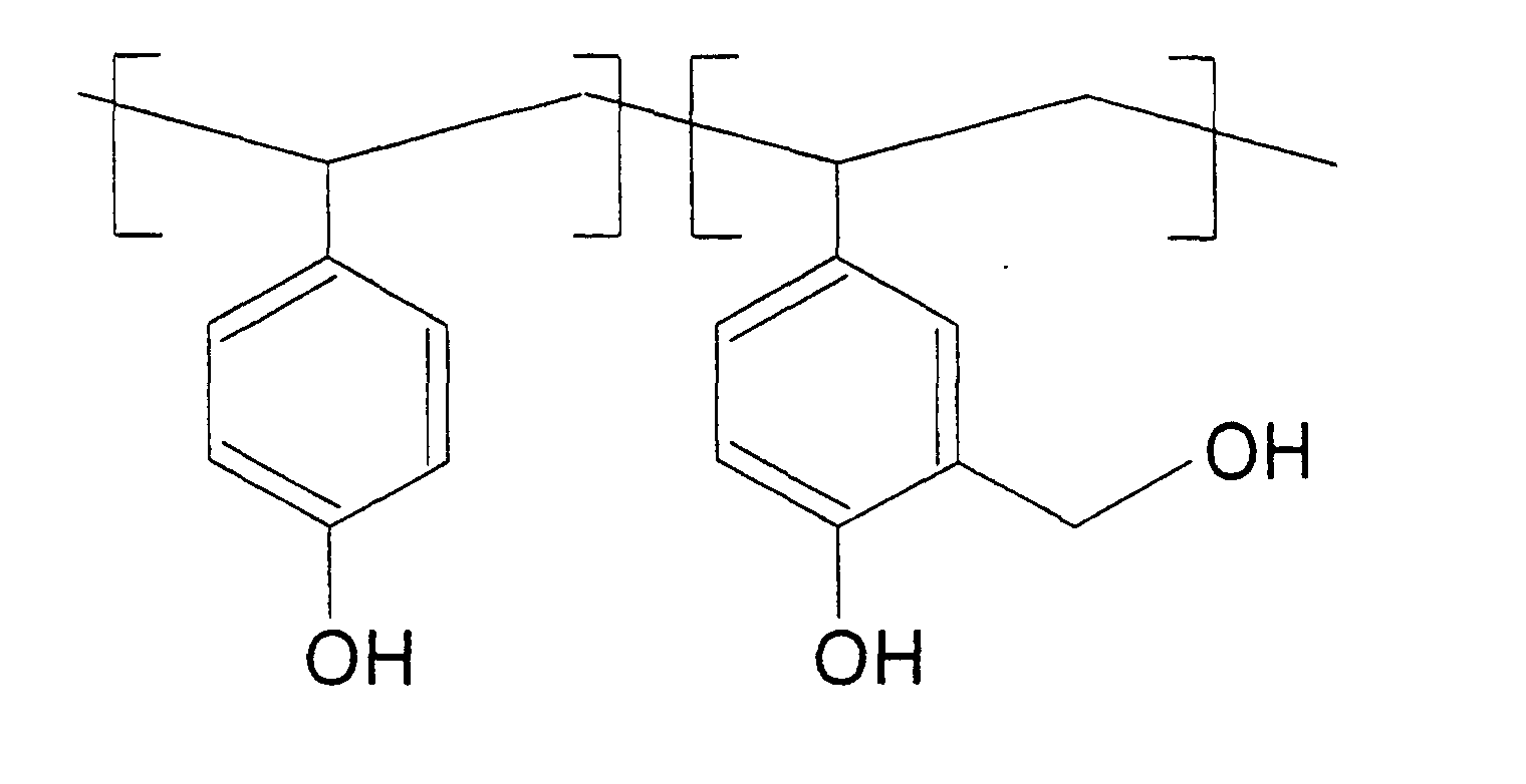
- a particularly suitable methylol polyvinyl phenol compound is a copolymer of the following structure:
- Suitable latent acid generating compounds are latent Bronsted acids and haloalkyl-substituted-s-triazines.
- latent Bronsted acid generators are iodonium, sulphonium, phosphonium, selenonium, diazonium and arsonium salts and particularly salts of fluorophosphoric acid.
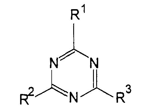
- haloalkyl-substituted-s-triazine is used as the latent acid generating compound preferably it is of the formula:- wherein R 1 is a substituted or unsubstituted aliphatic or aromatic group, R 2 and R 3 are each a trihaloalkyl group.
- a particularly useful diazonium salt for use as an acid generator is the compound of formula:-
- Diazonium salts are decomposed by U.V. light to liberate an acid but as diazonium salts can not be light-sensitised they are not decomposed by infra-red light. However, if an infra-red absorber is present in the composition which converts infra-red light to heat then the diazonium salts which are heat sensitive are decomposed as in the examples which follow.
- Carbon black is a useful infra-red absorbing agent which converts infra-red radiation to heat.
- Other pigments can also be used.
- infra-red sensitising dyes examples include dyes of the following classes, squarylium, croconate, cyanine, merocyanine, indolizine, pyrylinium or a metal dithiolene dye.
- composition of the present invention is of particular use because it can be UV imaged in the normal manner using a mask or it can be imaged by a laser digitally. Also negative plates or direct positive plates can be prepared.
- a method of preparing a lithographic printing plate which comprises infra-red laser imaging a lithographic printing plate precursor as just set forth, heating the imaged plate overall and then subjecting the heated plate to development in an aqueous alkali solution to yield a negative working plate.
- the infra-red absorbing compound is one whose absorption spectrum is significant at the wavelength output of the laser which is to be used in the method of the present invention.
- gallium arsenide diode lasers emit at 830nm and Nd YAG lasers emit at 1064nm.
- the laser imaging of the plate followed by heat treatment hardens the composition imagewise.
- the unexposed composition on the plate is removed by the development step. This yields a negative image.
- the lithographic plate precursor of the present invention can be used to produce a direct positive plate.
- the plate is imagewise exposed through a mask to U.V. light or directly using a laser then developed.
- the exposed areas become alkali-soluble leaving the unexposed areas as the direct positive image.
- a heat insulator layer which attenuates the thermal conductivity to the base.
- the base is an aluminium plate base.
- the base In the preparation of an aluminium plate base for use in lithography there usually forms on the base a thin layer of aluminium oxide which is often between 2 to 3 ⁇ m in thickness.
- a layer of aluminium oxide is formed which is from 10 to 15 ⁇ m in thickness.
- Such a thickness of aluminium oxide acts very efficiently as a heat insulation layer.
- the thickness of the aluminium oxide layer is much greater than 15 ⁇ m an unstable layer can be formed which tends to flake off.
- Thermal conduction from the imaging layer may also be reduced by optimisation of anodising conditions to produce an anodic sub-layer of low porosity and low thermal conductivity.
- Thermal conduction from the imaging layer may also be reduced by use of hydrophilising layers such as those described in E.P.A. 626273.
- infra-red absorber Preferably as much infra-red absorber is present in the photosensitive composition so as not to interfere with the alternative U.V. exposure method.
- Dyes with the selective IR absorption can be present in a greater amount than a black body such as carbon.
- the base which can be used as a lithographic base is preferably an aluminium plate which has undergone the usual anodic, graining and post-anodic treatments well known in the lithographic art for enabling a photosensitive composition to be coated thereon.
- Another base material which may be used in the method of the present invention is a plastics material base or a treated paper base as used in the photographic industry.
- a particularly useful plastics material base is polyethylene terephthalate which has been subbed to render its surface hydrophilic.
- a so-called resin coated paper which has been corona discharge treated may also be used.
- An example of a suitable practical developing solution is an aqueous solution of 8% metasilicate, 0.1% of an organic phosphate ester of an ethoxylated alcohol and 0.01% of polyoxylpropylane methyl ethyl ammonium chloride.
- the coated substrate to be imaged was cut into a circle of 105mm diameter and placed on a disc that could be rotated at a constant speed of 2500 revolutions per minute.
- Adjacent to the spinning disc a translating table held the source of the laser beam so that the laser beam impinged normal to the coated substrate, while the translating table moved the laser beam radially in a linear fashion with respect to the spinning disk.
- the exposed image was in the form of a spiral whereby the image in the centre of the spiral represented slow laser scanning speed and long exposure time and the outer edge of the spiral represented fast scanning speed and short exposure time.
- the laser used was a single mode 830nm wavelength 200mW laser diode which was focused to a 10 ⁇ m spot.
- the laser power supply was a stabilised constant current source.
- the exposed disc was developed by immersing in the alkaline developer solution which removed the non-imaged coating leaving the exposed spiral image.
- Exposure time quoted in the examples was the calculated time required for the laser to pass over a theoretical 10 ⁇ m square on the surface of the substrate and corresponded to an exposure sufficient to produce an image line that resisted the developer treatment.
- the precursors prepared in the present invention can also be U.V. imaged to yield a positive working plate or can be reversal imaged to yield a negative working plate.
- the U.V. source may be a carbon arc lamp, a mercury vapour lamp, a fluorescent lamp or a tungsten filament lamp.
- the latent acid generating compounds were : and the IR sensitising dye A:
- DMF dimethyl formamide
- a solution containing 0.59g of 40% w/w novolak A in methoxypropanol, 0.24g polyvinyl phenol substituted with methylol groups, 0.055g of acid generator B, 0.22g of dye A, 3.09g of methoxypropanol and 1g of DMF was prepared and coated onto a substrate consisting of a sheet of aluminium that had been electrograined and anodised, giving a coating weight of 1.3gm -2 after thoroughly drying at 100°C in an oven for 3 minutes.
- the resulting plate was imaged using a 200mW laser diode at a wavelength of 830nm using the imaging device described previously. The plate was then heated to 130°C for one minute. The plate was then developed using the alkaline developer B for 30 seconds which removed the parts of the coating on the plate that were not struck by the laser beam giving an image.
- the imaging energy density required to give a suitable image was 200mJ/cm -2 using developer B.
- a solution containing 0.59g of 40% w/w novolak A in methoxypropanol, 0.24g polyvinyl phenol substituted with hydroxymethyl groups, 0.055g of acid generator A, 0.22g of dye A, 3.09g of methoxypropanol and 1g of DMF was prepared and coated onto a substrate consisting of a sheet of aluminium that had been electrograined and anodised, giving a coating weight of 1.3gm -2 after thoroughly drying at 100°C in an oven for 3 minutes.
- the resulting plate was imaged using a 200mW laser diode at a wavelength of 830nm using the imaging device described previously. The plate was then heated to 100°C for one minute. The plate was then developed using the alkaline developer B for 120 seconds which removed the parts of the coating on the plate that were not struck by the laser beam giving an image.
- the imaging energy density required to give a suitable image was 200mJ/cm -2 using developer B.
- the resulting plate was imaged using a 200mW laser diode at a wavelength of 830nm using the imaging device described previously. The plate was then heated to 100°C for one minute. The plate was then developed using the alkaline developer B for 120 seconds which removed the parts of the coating on the plate that were not struck by the laser beam giving an image.
- the imaging energy density required to give a suitable image was 200m/cm -2 using developer C.
- a lithographic plate precursor as prepared in the examples could be imaged conventionally: a positive plate can be obtained by UV imaging and developing and a negative plate can be obtained by UV imaging, heating and developing.
- any suitable light of sufficient power which is absorbed by components in the system to generate heat in the composition can be used.
- a solution containing 0.59g of 40% w/w novolak A in methoxypropanol, 0.59g of a 40% polyvinyl phenol (substituted with methylol groups) solution in methoxypropanol, 0.55g of a 10% solution of acid generator C in DMF, 0.022g of dye A, 1.51g of methoxypropanol and 1.73g of DMF was prepared and coated onto a substrate consisting of a sheet of aluminium that had been electrograined and anodised, giving a coating film weight of 1.3gm -2 after thoroughly drying at 100°C in an oven for 3 minutes.
- the resulting plate was imaged using a 200mW laser diode at a wavelength of 830nm using the imaging device described previously. The plate was then heated to 100°C for one minute. The plate was then developed using the alkaline developer C for 120 seconds which removed the parts of the coating on the plate that were not struck by the laser beam giving an image.
- the imaging energy density required to give a suitable image was 480mJ/cm -2 using developer B.
- a solution containing 1.18g of 40% w/w novolak B in methoxypropanol, 0.14g of a 40% solution of bis(hydroxymethyl)p-cresol in methoxypropanol, 0.055g of a 10% solution of acid generator C in DMF, 0.022g of dye A, 1.42g of methoxypropanol and 1.96g of DMF was prepared and coated onto a substrate consisting of a sheet of aluminium that had been electrograined and anodised, giving a coating film weight of 1.3gm -2 after thoroughly drying at 100°C in an oven for 3 minutes.
- the resulting plate was imaged using a 200mW laser diode at a wavelength of 830nm using the imaging device described previously. The plate was then heated to 100°C for one minute. The plate was then developed using the alkaline developer C for 120 seconds which removed the parts of the coating on the plate that were not struck by the laser beam giving an image.
- the imaging energy density required to give a suitable image was 600mJ/cm -2 using developer B.
Landscapes
- Engineering & Computer Science (AREA)
- Manufacturing & Machinery (AREA)
- Photosensitive Polymer And Photoresist Processing (AREA)
- Materials For Photolithography (AREA)
Description


The imaged substrate was developed for 30 seconds.
In the Example which follows the condensing agent was polyvinyl phenol with substituted methylol groups


| COMPONENT | WEIGHT (g) | % SOLIDS |
| Novolak A | 0.59 | 42 |
| Methylol-P.V.Phenol | 0.59 | 42 |
| Acid generator B | 0.55 | 12 |
| Dye A | 0.022 | 4 |
| Methoxypropanol | 3.09 | 0 |
| DMF | 1 | 0 |
| COMPONENT | WEIGHT (g) | % SOLIDS |
| novolak A | 0.59 | 42 |
| methylol-P.V.Phenol | 0.24 | 42 |
| acid generator A | 0.02 | 12 |
| dye A | 0.022 | 4 |
| methoxypropanol | 3.09 | 0 |
| DMF | 1 | 0 |
| COMPONENT | WEIGHT (g) | % SOLIDS |
| novolak B | 1.18 | 81.8 |
| bis(hydroxymethyl) | 0.55 | 9.6 |
| p-cresol | ||
| acid generator B | 0.02 | 4.8 |
| dye A | 0.022 | 3.8 |
| methoxypropanol | 3.09 | 0 |
| DMF | 1 | 0 |
| COMPONENT | WEIGHT (g) | % SOLIDS |
| novolak B | 1.18 | 81.8 |
| bis(hydroxymethyl) | 0.55 | 9.6 |
| p-cresol | ||
| acid generator A | 0.02 | 4.8 |
| dye A | 0.022 | 3.8 |
| methoxypropanol | 3.09 | 0 |
| DMF | 1 | 0 |
| COMPONENT | WEIGHT (g) | % SOLIDS |
| novolak A | 0.59 | 42 |
| methylol-P.V. phenol | 0.59 | 42 |
| acid generator C | 0.55 | 12 |
| dye A | 0.022 | 4 |
| Methoxypropanol | 1.51 | 0 |
| DMF | 1.73 | 0 |
| COMPONENT | WEIGHT (g) | % SOLIDS |
| Novolak B | 1.18 | 81.8 |
| bis(hydroxymethyl) | ||
| p-cresol | 0.55 | 9.6 |
| acid generator C | 0.02 | 4.8 |
| dye A | 0.022 | 3.8 |
| Methoxypropanol | 3.09 | 0 |
| DMF | 1 | 0 |
Claims (11)
- A lithographic printing plate precursor comprising on a support a radiation sensitive composition which comprises (1) a novolak resin, (2) a condensing agent for the novolac resin which is a either a methylol polyvinyl phenol compound or a bishydroxymethyl compound, (3) a radiation sensitive latent acid generating compound and (4) an infra red absorbing compound or an infra-red sensitising dye.
- A lithographic printing plate precursor according to claim 1 wherein the novolak resin is derived from m-cresol and formaldehyde.
- A lithographic printing plate precursor according to claim 1 wherein the bis hydroxymethyl condensing agent is 2,6-bis(hydroxymethyl)-p-cresol.
- A lithographic printing plate precursor according to claim 1 wherein the methylol polyvinyl phenol compound has the following structure:-
- A lithographic printing plate precursor according to claim 1 wherein the radiation sensitive latent acid generating compound is a latent Bronsted acid or a haloalkyl-substutited s-triazine.
- A lithographic printing plate precursor according to claim 5 wherein the latent acid generating compound is an iodonium, sulphonium, phosphonium, selenonium, diazonium or arsonium salt or a fluorophosphoric acid.
- A lithographic plate precursor according to claim 6 wherein the iodonium salt is iodonium hexafluorophosphate.
- A lithographic plate precursor according to claim 6 wherein the diazonium salt has the formula:-

- A lithographic printing plate precursor according to claim 5 wherein the haloalkyl-substituted s-triazine is of the formula:-wherein R1 is a substituted or unsubstituted aliphatic or aromatic radical, and R2 and R3 are each a haloalkyl group.

- A lithographic printing plate precursor according to claim 1 wherein the infra-red absorbing compound is carbon black.
- A lithographic plate precursor according to claim 1 wherein the infra-red sensitising dye is a dye of one of the following classes of dye:- squarylium, croconate, cyanine, merocyanine, indolizine, pyrylinium or metal dithiolene dye.
Applications Claiming Priority (3)
| Application Number | Priority Date | Filing Date | Title |
|---|---|---|---|
| GB9700877A GB9700877D0 (en) | 1997-01-17 | 1997-01-17 | Lithographic plates |
| GB9700877 | 1997-01-17 | ||
| PCT/GB1998/000132 WO1998031544A1 (en) | 1997-01-17 | 1998-01-15 | Lithographic plates |
Publications (2)
| Publication Number | Publication Date |
|---|---|
| EP0952924A1 EP0952924A1 (en) | 1999-11-03 |
| EP0952924B1 true EP0952924B1 (en) | 2002-03-06 |
Family
ID=10806103
Family Applications (1)
| Application Number | Title | Priority Date | Filing Date |
|---|---|---|---|
| EP98900616A Expired - Lifetime EP0952924B1 (en) | 1997-01-17 | 1998-01-15 | Lithographic plates |
Country Status (4)
| Country | Link |
|---|---|
| EP (1) | EP0952924B1 (en) |
| DE (1) | DE69804079T2 (en) |
| GB (1) | GB9700877D0 (en) |
| WO (1) | WO1998031544A1 (en) |
Families Citing this family (2)
| Publication number | Priority date | Publication date | Assignee | Title |
|---|---|---|---|---|
| US6555283B1 (en) * | 2000-06-07 | 2003-04-29 | Kodak Polychrome Graphics Llc | Imageable element and waterless printing plate |
| US20130233190A1 (en) * | 2012-03-06 | 2013-09-12 | Presstek, Inc. | Lithographic imaging and printing with positive-working photoresponsive printing members |
Family Cites Families (4)
| Publication number | Priority date | Publication date | Assignee | Title |
|---|---|---|---|---|
| EP0288533A4 (en) * | 1986-10-20 | 1989-02-06 | Macdermid Inc | Image reversal system and process. |
| US5296332A (en) * | 1991-11-22 | 1994-03-22 | International Business Machines Corporation | Crosslinkable aqueous developable photoresist compositions and method for use thereof |
| EP0613050B1 (en) * | 1993-02-26 | 1997-03-26 | International Business Machines Corporation | Universal negative tone photoresist |
| US5372915A (en) * | 1993-05-19 | 1994-12-13 | Eastman Kodak Company | Method of making a lithographic printing plate containing a resole resin and a novolac resin in the radiation sensitive layer |
-
1997
- 1997-01-17 GB GB9700877A patent/GB9700877D0/en active Pending
-
1998
- 1998-01-15 DE DE69804079T patent/DE69804079T2/en not_active Expired - Fee Related
- 1998-01-15 WO PCT/GB1998/000132 patent/WO1998031544A1/en not_active Ceased
- 1998-01-15 EP EP98900616A patent/EP0952924B1/en not_active Expired - Lifetime
Also Published As
| Publication number | Publication date |
|---|---|
| DE69804079D1 (en) | 2002-04-11 |
| DE69804079T2 (en) | 2002-10-24 |
| EP0952924A1 (en) | 1999-11-03 |
| WO1998031544A1 (en) | 1998-07-23 |
| GB9700877D0 (en) | 1997-03-05 |
Similar Documents
| Publication | Publication Date | Title |
|---|---|---|
| WO1996020429A1 (en) | Lithographic plate | |
| EP0672954B1 (en) | Radiation-sensitive composition containing a resole resin, a novolac resin, an infrared absorber and a triazine and use thereof in lithographic printing plates | |
| EP0625728B1 (en) | Radiation-sensitive composition containing a resole resin and a novolak resin and use thereof in lithographic plates | |
| US5466557A (en) | Radiation-sensitive composition containing a resole resin, a novolac resin, a latent bronsted acid, an infrared absorber and terephthalaldehyde and use thereof in lithographic printing plates | |
| US6537735B1 (en) | Pattern-forming methods and radiation sensitive materials | |
| EP0819980B1 (en) | An IR radiation-sensitive imaging element and a method for producing lithographic plates therewith | |
| CN1954007A (en) | Thermally reactive infrared absorption polymers and their use in a heat sensitive lithographic printing plate | |
| EP0819985B1 (en) | A radiation sensitive imaging element and a method for producing lithographic plates therewith | |
| US6977131B2 (en) | Selected polymeric sulfonate acid generators and their use in processes for imaging radiation-sensitive elements | |
| JPH10254143A (en) | Manufacture of positive-action planographic printing plate | |
| US6489078B1 (en) | IR radiation-sensitive imaging element and a method for producing lithographic plates therewith | |
| JP2001281856A (en) | Infrared ray(ir) sensitive image forming material | |
| US6077641A (en) | Lithographic plates | |
| EP0956948A1 (en) | IR and UV radiation -sensitive composition and lithographic plate | |
| US6723495B2 (en) | Water-developable negative-working ultraviolet and infrared imageable element | |
| US6140022A (en) | Radiation sensitive imaging element and a method for producing lithographic plates therewith | |
| US6352814B1 (en) | Method of forming a desired pattern | |
| EP0952924A1 (en) | Lithographic plates | |
| US6248505B1 (en) | Method for producing a predetermined resist pattern | |
| JPH10186649A (en) | Infrared sensitive picture forming composition, element and its method | |
| JP3514900B2 (en) | Lithographic printing plate | |
| JP4633295B2 (en) | Printing plate method for photosensitive lithographic printing plate | |
| EP0882583A1 (en) | A heat sensitive imaging element and a method for producing lithographic plates therewith | |
| JP3802270B2 (en) | Positive photosensitive composition and positive photosensitive lithographic printing plate | |
| US20120192741A1 (en) | Method for preparing lithographic printing plates |
Legal Events
| Date | Code | Title | Description |
|---|---|---|---|
| PUAI | Public reference made under article 153(3) epc to a published international application that has entered the european phase |
Free format text: ORIGINAL CODE: 0009012 |
|
| 17P | Request for examination filed |
Effective date: 19990622 |
|
| AK | Designated contracting states |
Kind code of ref document: A1 Designated state(s): DE FR GB |
|
| GRAG | Despatch of communication of intention to grant |
Free format text: ORIGINAL CODE: EPIDOS AGRA |
|
| 17Q | First examination report despatched |
Effective date: 20010411 |
|
| GRAG | Despatch of communication of intention to grant |
Free format text: ORIGINAL CODE: EPIDOS AGRA |
|
| GRAH | Despatch of communication of intention to grant a patent |
Free format text: ORIGINAL CODE: EPIDOS IGRA |
|
| GRAH | Despatch of communication of intention to grant a patent |
Free format text: ORIGINAL CODE: EPIDOS IGRA |
|
| REG | Reference to a national code |
Ref country code: GB Ref legal event code: IF02 |
|
| GRAA | (expected) grant |
Free format text: ORIGINAL CODE: 0009210 |
|
| AK | Designated contracting states |
Kind code of ref document: B1 Designated state(s): DE FR GB |
|
| REF | Corresponds to: |
Ref document number: 69804079 Country of ref document: DE Date of ref document: 20020411 |
|
| ET | Fr: translation filed | ||
| PGFP | Annual fee paid to national office [announced via postgrant information from national office to epo] |
Ref country code: FR Payment date: 20030110 Year of fee payment: 6 |
|
| PLBE | No opposition filed within time limit |
Free format text: ORIGINAL CODE: 0009261 |
|
| STAA | Information on the status of an ep patent application or granted ep patent |
Free format text: STATUS: NO OPPOSITION FILED WITHIN TIME LIMIT |
|
| PGFP | Annual fee paid to national office [announced via postgrant information from national office to epo] |
Ref country code: GB Payment date: 20030115 Year of fee payment: 6 |
|
| PGFP | Annual fee paid to national office [announced via postgrant information from national office to epo] |
Ref country code: DE Payment date: 20030123 Year of fee payment: 6 |
|
| 26N | No opposition filed |
Effective date: 20021209 |
|
| PG25 | Lapsed in a contracting state [announced via postgrant information from national office to epo] |
Ref country code: GB Free format text: LAPSE BECAUSE OF NON-PAYMENT OF DUE FEES Effective date: 20040115 |
|
| PG25 | Lapsed in a contracting state [announced via postgrant information from national office to epo] |
Ref country code: DE Free format text: LAPSE BECAUSE OF NON-PAYMENT OF DUE FEES Effective date: 20040803 |
|
| GBPC | Gb: european patent ceased through non-payment of renewal fee |
Effective date: 20040115 |
|
| PG25 | Lapsed in a contracting state [announced via postgrant information from national office to epo] |
Ref country code: FR Free format text: LAPSE BECAUSE OF NON-PAYMENT OF DUE FEES Effective date: 20040930 |
|
| REG | Reference to a national code |
Ref country code: FR Ref legal event code: ST |