EP0952658A2 - Electric motor of the electronic commutation type - Google Patents
Electric motor of the electronic commutation type Download PDFInfo
- Publication number
- EP0952658A2 EP0952658A2 EP99107629A EP99107629A EP0952658A2 EP 0952658 A2 EP0952658 A2 EP 0952658A2 EP 99107629 A EP99107629 A EP 99107629A EP 99107629 A EP99107629 A EP 99107629A EP 0952658 A2 EP0952658 A2 EP 0952658A2
- Authority
- EP
- European Patent Office
- Prior art keywords
- fact
- motor according
- walls
- motor
- itself
- Prior art date
- Legal status (The legal status is an assumption and is not a legal conclusion. Google has not performed a legal analysis and makes no representation as to the accuracy of the status listed.)
- Withdrawn
Links
Images


Classifications
-
- H—ELECTRICITY
- H02—GENERATION; CONVERSION OR DISTRIBUTION OF ELECTRIC POWER
- H02K—DYNAMO-ELECTRIC MACHINES
- H02K29/00—Motors or generators having non-mechanical commutating devices, e.g. discharge tubes or semiconductor devices
- H02K29/06—Motors or generators having non-mechanical commutating devices, e.g. discharge tubes or semiconductor devices with position sensing devices
- H02K29/08—Motors or generators having non-mechanical commutating devices, e.g. discharge tubes or semiconductor devices with position sensing devices using magnetic effect devices, e.g. Hall-plates, magneto-resistors
-
- H—ELECTRICITY
- H02—GENERATION; CONVERSION OR DISTRIBUTION OF ELECTRIC POWER
- H02K—DYNAMO-ELECTRIC MACHINES
- H02K1/00—Details of the magnetic circuit
- H02K1/06—Details of the magnetic circuit characterised by the shape, form or construction
- H02K1/12—Stationary parts of the magnetic circuit
- H02K1/14—Stator cores with salient poles
- H02K1/146—Stator cores with salient poles consisting of a generally annular yoke with salient poles
- H02K1/148—Sectional cores
-
- H—ELECTRICITY
- H02—GENERATION; CONVERSION OR DISTRIBUTION OF ELECTRIC POWER
- H02K—DYNAMO-ELECTRIC MACHINES
- H02K11/00—Structural association of dynamo-electric machines with electric components or with devices for shielding, monitoring or protection
- H02K11/30—Structural association with control circuits or drive circuits
- H02K11/33—Drive circuits, e.g. power electronics
-
- H—ELECTRICITY
- H02—GENERATION; CONVERSION OR DISTRIBUTION OF ELECTRIC POWER
- H02K—DYNAMO-ELECTRIC MACHINES
- H02K21/00—Synchronous motors having permanent magnets; Synchronous generators having permanent magnets
- H02K21/12—Synchronous motors having permanent magnets; Synchronous generators having permanent magnets with stationary armatures and rotating magnets
- H02K21/14—Synchronous motors having permanent magnets; Synchronous generators having permanent magnets with stationary armatures and rotating magnets with magnets rotating within the armatures
- H02K21/16—Synchronous motors having permanent magnets; Synchronous generators having permanent magnets with stationary armatures and rotating magnets with magnets rotating within the armatures having annular armature cores with salient poles
-
- H—ELECTRICITY
- H02—GENERATION; CONVERSION OR DISTRIBUTION OF ELECTRIC POWER
- H02K—DYNAMO-ELECTRIC MACHINES
- H02K2211/00—Specific aspects not provided for in the other groups of this subclass relating to measuring or protective devices or electric components
- H02K2211/03—Machines characterised by circuit boards, e.g. pcb
-
- H—ELECTRICITY
- H02—GENERATION; CONVERSION OR DISTRIBUTION OF ELECTRIC POWER
- H02K—DYNAMO-ELECTRIC MACHINES
- H02K3/00—Details of windings
- H02K3/04—Windings characterised by the conductor shape, form or construction, e.g. with bar conductors
- H02K3/28—Layout of windings or of connections between windings
-
- H—ELECTRICITY
- H02—GENERATION; CONVERSION OR DISTRIBUTION OF ELECTRIC POWER
- H02K—DYNAMO-ELECTRIC MACHINES
- H02K5/00—Casings; Enclosures; Supports
- H02K5/04—Casings or enclosures characterised by the shape, form or construction thereof
- H02K5/22—Auxiliary parts of casings not covered by groups H02K5/06-H02K5/20, e.g. shaped to form connection boxes or terminal boxes
- H02K5/225—Terminal boxes or connection arrangements
Definitions
- the present invention refers to an electric motor of the electronic commutation type.
- the present invention will make reference, without losing any of its generality, to an electric motor of the commutation type which may be assembled to advantage to a petrol fuel pump, and which comprises a stator, a rotor coupled to said stator itself in such a way that said rotor may revolve around an axis of rotation, and an electronic device for supplying and controlling the said electric motor itself.
- the rotor comprises a driving shaft and a number of permanent magnets mounted on the driving shaft itself, while the stator comprises a number of teeth uniformly distributed around the axis of rotation, and an external frame, which contains and assembles the teeth, and defines with said teeth themselves respective hollows which are axially open and suitable for housing respective stator windings.
- Electric motors of the kind described above have some drawbacks in both structural and economic terms. From the structural point of view, the fact that there are a number of permanent magnets mounted on the driving shaft and the high rotation speed of the driving shaft itself mean that peripheral elements are necessary, for assembling and containing the magnets themselves, suitable for opposing centrifugal forces, while the shape of the hollows means that winding must be carried out by means of winding devices, which, despite the advances which have taken place in recent years, still result in low productive speeds and low filling capacity. It is obvious that each of the drawbacks described above has direct negative repercussions in terms of the production cost of each electric motor itself, with the end result that the realisation of high volume of production is extremely onerous.
- the aim of the present invention is to realise an electric motor of the electronic commutation type, which, other than presenting a high reliability co-efficient, will permit that the drawbacks described above be overcome in a simple and cost-effective manner.
- An electric motor of the electronic commutation type will be realised according to the present invention comprising a stator which in turn comprises a number of radial teeth, a rotor coupled to said stator itself in such a way that said rotor may revolve around an axis of rotation, and an electronic device for supplying and controlling the motor itself, the motor being characterised by the fact that the stator further comprises an assembly element of the radial teeth, realised in electrically insulated material and by co-molding of the radial teeth themselves; said rotor comprising a permanent magnet realised in a single piece.
- FIGS. 1-5, 1 indicates an electric motor with a biphase unipolar structure in its entirety, said motor being suitable to be assembled with a fuel pump 2 mounted in succession to the motor 1 itself along an A axis of rotation of the motor 1.
- the motor 1 comprises an electronic device 3 for supplying and controlling, a rotor 4 which may revolve around the A axis arranged along the A axis itself in an intermediate position between the device 3 and the pump 2, and a stator 5, which supports, in such a way that it may revolve and in its own interior, the rotor 4, and constrains axially between them the pump 2 and the motor 1 themselves.
- the rotor 4 comprises a driving shaft 6, which is connected to the stator 5 in such a way that it may revolve in correspondence to the respective opposite extremities by means of the interposition of two bushings 7 and 8, and presents, from the part of the bushing 8, an end portion 9 angularly coupled to the pump 2.
- the rotor 4 further comprises a cylindrical magnet 10, which is realised by extrusion in a single piece and is comprised of anisotropic ferrite, and presents diametric magnetisation at two poles.
- the magnet 10 is splined to the driving shaft 6 in a position which is substantially intermediate between the two bushings 7 and 8, and is co-molded to the driving shaft 6 itself in such a way as to render the rotor 4 itself intrinsically balanced, and being realised as previously described in a single piece.
- the magnet 10 is completely lacking in any kind of peripheral element for assembly or containment whatsoever.
- the stator 5 comprises four stator teeth 11, or stator pole shoes, uniformly distributed around the A axis, and an element 12 for assembling and covering the teeth 11 themselves which is realised in electrically insulating plastic material and by co-molding of the teeth 11 themselves.
- Each tooth 11 is defined by a respective stack 13 of shaped metallic laminations 14, each of which, as is better illustrated in FIG. 12, is obtained from a tape 15, is of a shape substantially in the form of a T, and comprises a respective portion 16 with a curved base, and a respective head portion 17 which is transverse to the relative portion 16 itself, and is provided at one end with respective lateral notches 18 with a substantially rectangular section.
- the laminations 14 of each tape 15 are obtained in counterpoised positions in relation to each other in such a way as to alternate, on each edge of the tape 15 itself, a base portion 16 and a top/head portion 17 reducing wastage in the tape 15 to a minimum, while the laminations 14 of each tooth 11 are pre-assembled in relation to each other by means of "stitching" after they have been arranged side by side and in contact one with the other, and the relative notches 18 define a respective guiding device 19 comprising two housings 19a and two longitudinal projecting parts 19b parallel to each other and to the A axis, and from which the housing 19a presents a determined depth P with regard to the projecting parts 19b.
- the element 12 comprises a cylinder 20 coaxial to the A axis, inside of which are buried all the base portions 16 of the laminations 14, and further comprising, for each tooth 11, a pair of radial walls 21 arranged in contact with the head portion 17 of the laminations 14 of the relative stack 13, and a further radial wall 22, which extends transversely from the cylinder 20 and is arranged in a substantially intermediate position between two walls 21.
- Each wall 22 defines, together with the cylinder 20 and the two adjacent walls 21, two hollows 23 electrically insulated one from the other by the wall 22 itself, and radially open towards the exterior of the rotor 4.
- the hollows 23 are occupied by respective spool windings 24, which make up part of the stator 5, and are realised before completing the assembly of the motor 1 by means of a spool winder (of a well-known type, which is not illustrated) presenting a high level of winding speed and a high filling co-efficient.
- the cylinder 20 comprises, on the part turned towards the device 3, a wire guide edge 25 extending around the A axis and suitable for co-operating with the wires of the windings 24, two housings 26 obtained along the edge 25 itself, and two seats 27 and 28 occupied by the bushings 7 and 8 respectively:
- the seat 28 and the bushing 8 are coaxial to the A axis and are internally and, respectively, externally cylindrical to permit an axial movement of the bushing 8 itself, while the seat 27 and the bushing 7 are internally and, respectively, externally spherical not only to permit the rotation of the bushing 7, but also to permit the assembly of the said bushing 7.
- the seat 28 further presents an external appendix 29 arranged transversely to the A axis, and suitable for acting on the driving shaft 6 to limit the axial play of the driving shaft 6 itself.
- the stator 5 further comprises a continuous tubular frame 30 arranged around the teeth 11 and an element 12, and two discontinuous tubular liners 31 and 32, which are coaxially mounted in relation to each other one behind the other and between the frame 30 and the hollow 23 to radially close the hollow 23 itself towards the exterior, said liners 31 and 32 are obtained from respective tapes 33 and 34 which are of a determined thickness.
- the tape 33, 34 presents three slots 35', 35" longitudinally closed and obtained by partially notching the tape 33, 34 itself, two transverse edges 36 of the same length, and two edges 37, which, once they are alongside each other, define a further slot, 38', 38'', which is open longitudinally, in relation to each other: the slots 35' and 38' of the liner 31 are in juxtaposition to the slots 35'' and 38'' of the liner 32 and are narrower than the width presented by the slots 35'' and 38'', which, in turn, are of a width equal to a width of the head portions 17 of the laminations 14 in correspondence to the projecting parts 19b.
- the tape 33 further presents, for each edge 36, four notches 39 which are obtained along the edge 36 itself, and the relative liner 31 is an internal liner arranged directly facing the hollows 23; while the tape 34 presents, for each edge 36, four hooks 40 which are obtained along the edge 36 itself, and the relative liner 32 is an external liner arranged between the liner 31 and the frame 30.
- the depth P of the housings 19a is such that it permits the realisation of the liners 31 and 32 starting from the cut down size of the tape 33 and 34 presenting in the respective development plan the same length, or presenting, as previously described, the edges 36 of an equal length in relation to each other: in fact, the depth P is such as to compensate for the different circumferential development of the liners 31 and 32 due to the assembly of the liners 31 and 32 themselves one on top of the other and on different respective diameters.
- the liners 31 and 32 once they have been placed one on top of the other and on the body of the motor 1, are inserted into the frame 30, which acts with the liners 31 and 32 themselves to close the magnetic flow and, as it has an axial length greater than the axial length of the liners 31 and 32, defines two seats 41 which are internally limited by the edges 36.
- the electronic device 3 and the pump 2 are mounted inside the seats 41 so that they abut against the edges 36, and are then fixed in their respective positions by a circular clinch of the corresponding end edges 42 of the frame 30.
- the electronic device 3 comprises an electronic card 43 arranged to abut against the edges 36 of the liners 31 and 32, four passing tubes 44 mounted through the electronic card 43 itself and internally restricted by the terminals 45 of the windings 24, two Hall sensors 46 arranged inside the housings 26 four MOSFET circuits mounted on the electronic card 43 opposite the sensors 46 with relation to the electronic card 43 itself, and a pair of external FASTOM connectors 48 which are welded to the electronic card 43 in the same place as the circuits 47.
- the device 3 also comprises a resistor 49 mounted on each control circuit of the circuits 47, and suitable for prolonging the commutation time.
- the device 3 is illustrated in its basic configuration, while in FIG. 14 the device 3 is illustrated in its final co-molded configuration, that is with all the relative components immersed in insulating material to protect the device 3 itself from suffering any damage from the surrounding environment, when in use, that might impair its functioning properly.
- the terminals 45 of the windings 24 are anchored to the assembly element 12 and, after being inserted inside the relative tubes 44, they are connected to the tubes 44 themselves by crimping and electric welding without welding the material.
- FIGS. 15 and 16 illustrate the plan of the windings in an anti-clockwise direction of rotation on the side of the electronic device 3 and, according to the illustration shown in these diagrams, the electronic card 43 is indirectly supplied by a battery 50 connected to the windings 24 coupled two by two in phase in relation to each other, that is the electronic card 43 is supplied via the windings 24 themselves which means that a filter is obtained at zero cost to render the electronic device 3 immune from any disturbances and that the need for electrolytic levelling condensers, which is a typical feature of this kind of electronic device, is eliminated.
- the electric motor forces maintain supply at a level higher than that of the battery.
Abstract
Description
- The present invention refers to an electric motor of the electronic commutation type.
- In particular, the present invention will make reference, without losing any of its generality, to an electric motor of the commutation type which may be assembled to advantage to a petrol fuel pump, and which comprises a stator, a rotor coupled to said stator itself in such a way that said rotor may revolve around an axis of rotation, and an electronic device for supplying and controlling the said electric motor itself.
- Generally, in electric motors of the type described above, the rotor comprises a driving shaft and a number of permanent magnets mounted on the driving shaft itself, while the stator comprises a number of teeth uniformly distributed around the axis of rotation, and an external frame, which contains and assembles the teeth, and defines with said teeth themselves respective hollows which are axially open and suitable for housing respective stator windings.
- Electric motors of the kind described above have some drawbacks in both structural and economic terms. From the structural point of view, the fact that there are a number of permanent magnets mounted on the driving shaft and the high rotation speed of the driving shaft itself mean that peripheral elements are necessary, for assembling and containing the magnets themselves, suitable for opposing centrifugal forces, while the shape of the hollows means that winding must be carried out by means of winding devices, which, despite the advances which have taken place in recent years, still result in low productive speeds and low filling capacity. It is obvious that each of the drawbacks described above has direct negative repercussions in terms of the production cost of each electric motor itself, with the end result that the realisation of high volume of production is extremely onerous.
- The aim of the present invention is to realise an electric motor of the electronic commutation type, which, other than presenting a high reliability co-efficient, will permit that the drawbacks described above be overcome in a simple and cost-effective manner.
- An electric motor of the electronic commutation type will be realised according to the present invention comprising a stator which in turn comprises a number of radial teeth, a rotor coupled to said stator itself in such a way that said rotor may revolve around an axis of rotation, and an electronic device for supplying and controlling the motor itself, the motor being characterised by the fact that the stator further comprises an assembly element of the radial teeth, realised in electrically insulated material and by co-molding of the radial teeth themselves; said rotor comprising a permanent magnet realised in a single piece.
- The invention will now be described with reference to the attached drawings, which illustrate an example of a non-limiting realisation of the invention, in which:
- FIG. 1
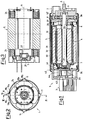
- illustrates, in axial section, a preferred form of realisation of the electric motor according to the present invention;
- FIG. 2
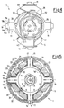
- is a transverse view of the electric motor shown in FIG. 1;
- FIG. 3
- illustrates, on an enlarged scale, a section along the line III-III shown in FIG. 2;
- FIGS 4 and 5
- show two transverse views, with some parts in section and some parts removed for the purpose of clarity, of the motor shown in FIG. 1;
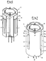
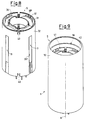
- FIGS. 6, 7, 8 and 9
- are perspective views of the respective assembly stages of the motor shown in FIG. 1;
- FIGS. 10, 11 and 12
- illustrate respective development plans of respective particulars of the motor shown in FIG. 1;
- FIGS. 13 and 14
- illustrate, on an enlarged scale, a particular of the motor shown in FIG. 1 in two different stages of production; and
- FIGS. 15 and 16
- are schematic views of an electronic particular and, respectively, of an electric particular of the motor shown in FIG. 1.
- With reference initially to FIG. 1, FIGS. 1-5, 1 indicates an electric motor with a biphase unipolar structure in its entirety, said motor being suitable to be assembled with a
fuel pump 2 mounted in succession to themotor 1 itself along an A axis of rotation of themotor 1. - The
motor 1 comprises anelectronic device 3 for supplying and controlling, a rotor 4 which may revolve around the A axis arranged along the A axis itself in an intermediate position between thedevice 3 and thepump 2, and astator 5, which supports, in such a way that it may revolve and in its own interior, the rotor 4, and constrains axially between them thepump 2 and themotor 1 themselves. - The rotor 4 comprises a driving shaft 6, which is connected to the
stator 5 in such a way that it may revolve in correspondence to the respective opposite extremities by means of the interposition of twobushings bushing 8, anend portion 9 angularly coupled to thepump 2. The rotor 4 further comprises acylindrical magnet 10, which is realised by extrusion in a single piece and is comprised of anisotropic ferrite, and presents diametric magnetisation at two poles. In particular, themagnet 10 is splined to the driving shaft 6 in a position which is substantially intermediate between the twobushings magnet 10 is completely lacking in any kind of peripheral element for assembly or containment whatsoever. - The
stator 5 comprises fourstator teeth 11, or stator pole shoes, uniformly distributed around the A axis, and anelement 12 for assembling and covering theteeth 11 themselves which is realised in electrically insulating plastic material and by co-molding of theteeth 11 themselves. Eachtooth 11 is defined by arespective stack 13 of shapedmetallic laminations 14, each of which, as is better illustrated in FIG. 12, is obtained from atape 15, is of a shape substantially in the form of a T, and comprises arespective portion 16 with a curved base, and arespective head portion 17 which is transverse to therelative portion 16 itself, and is provided at one end with respectivelateral notches 18 with a substantially rectangular section. Thelaminations 14 of eachtape 15 are obtained in counterpoised positions in relation to each other in such a way as to alternate, on each edge of thetape 15 itself, abase portion 16 and a top/head portion 17 reducing wastage in thetape 15 to a minimum, while thelaminations 14 of eachtooth 11 are pre-assembled in relation to each other by means of "stitching" after they have been arranged side by side and in contact one with the other, and therelative notches 18 define a respective guidingdevice 19 comprising twohousings 19a and two longitudinal projectingparts 19b parallel to each other and to the A axis, and from which thehousing 19a presents a determined depth P with regard to the projectingparts 19b. - The
element 12 comprises acylinder 20 coaxial to the A axis, inside of which are buried all thebase portions 16 of thelaminations 14, and further comprising, for eachtooth 11, a pair ofradial walls 21 arranged in contact with thehead portion 17 of thelaminations 14 of therelative stack 13, and a furtherradial wall 22, which extends transversely from thecylinder 20 and is arranged in a substantially intermediate position between twowalls 21. Eachwall 22 defines, together with thecylinder 20 and the twoadjacent walls 21, twohollows 23 electrically insulated one from the other by thewall 22 itself, and radially open towards the exterior of the rotor 4. Thehollows 23 are occupied byrespective spool windings 24, which make up part of thestator 5, and are realised before completing the assembly of themotor 1 by means of a spool winder (of a well-known type, which is not illustrated) presenting a high level of winding speed and a high filling co-efficient. - The
cylinder 20 comprises, on the part turned towards thedevice 3, awire guide edge 25 extending around the A axis and suitable for co-operating with the wires of thewindings 24, twohousings 26 obtained along theedge 25 itself, and twoseats bushings seat 28 and thebushing 8 are coaxial to the A axis and are internally and, respectively, externally cylindrical to permit an axial movement of thebushing 8 itself, while theseat 27 and thebushing 7 are internally and, respectively, externally spherical not only to permit the rotation of thebushing 7, but also to permit the assembly of the saidbushing 7. Theseat 28 further presents anexternal appendix 29 arranged transversely to the A axis, and suitable for acting on the driving shaft 6 to limit the axial play of the driving shaft 6 itself. - According to the illustration shown in FIGS. 6-11, the
stator 5 further comprises a continuoustubular frame 30 arranged around theteeth 11 and anelement 12, and two discontinuoustubular liners frame 30 and the hollow 23 to radially close the hollow 23 itself towards the exterior, saidliners respective tapes - In particular, the
tape tape transverse edges 36 of the same length, and twoedges 37, which, once they are alongside each other, define a further slot, 38', 38'', which is open longitudinally, in relation to each other: the slots 35' and 38' of theliner 31 are in juxtaposition to the slots 35'' and 38'' of theliner 32 and are narrower than the width presented by the slots 35'' and 38'', which, in turn, are of a width equal to a width of thehead portions 17 of thelaminations 14 in correspondence to the projectingparts 19b. - The
tape 33 further presents, for eachedge 36, fournotches 39 which are obtained along theedge 36 itself, and therelative liner 31 is an internal liner arranged directly facing thehollows 23; while thetape 34 presents, for eachedge 36, fourhooks 40 which are obtained along theedge 36 itself, and therelative liner 32 is an external liner arranged between theliner 31 and theframe 30. Once thewindings 34 are realised inside the hollows 23 (FIG. 6), and once thetapes liners housings 19a with an axial movement of theliner 31 in a determined direction of insertion, and by successively inserting the projectingparts 19b inside the slots 35'' and 38'' (FIG. 8) with an axial movement of theliner 32 in a direction of insertion opposite to that of the liner 31: in this way, the openings of the slots 35' and 38' are out of phase with regard to the openings of the slots 35'' and 38''. Furthermore, the depth P of thehousings 19a is such that it permits the realisation of theliners tape edges 36 of an equal length in relation to each other: in fact, the depth P is such as to compensate for the different circumferential development of theliners liners - The
liners motor 1, are inserted into theframe 30, which acts with theliners liners seats 41 which are internally limited by theedges 36. At this point, theelectronic device 3 and thepump 2 are mounted inside theseats 41 so that they abut against theedges 36, and are then fixed in their respective positions by a circular clinch of thecorresponding end edges 42 of the frame 30.According to the illustration shown in FIG. 13, theelectronic device 3 comprises anelectronic card 43 arranged to abut against theedges 36 of theliners passing tubes 44 mounted through theelectronic card 43 itself and internally restricted by theterminals 45 of thewindings 24, twoHall sensors 46 arranged inside thehousings 26 four MOSFET circuits mounted on theelectronic card 43 opposite thesensors 46 with relation to theelectronic card 43 itself, and a pair ofexternal FASTOM connectors 48 which are welded to theelectronic card 43 in the same place as thecircuits 47. According to the illustration shown in FIG. 15, thedevice 3 also comprises aresistor 49 mounted on each control circuit of thecircuits 47, and suitable for prolonging the commutation time. - In FIG. 13 the
device 3 is illustrated in its basic configuration, while in FIG. 14 thedevice 3 is illustrated in its final co-molded configuration, that is with all the relative components immersed in insulating material to protect thedevice 3 itself from suffering any damage from the surrounding environment, when in use, that might impair its functioning properly. Instead, theterminals 45 of thewindings 24 are anchored to theassembly element 12 and, after being inserted inside therelative tubes 44, they are connected to thetubes 44 themselves by crimping and electric welding without welding the material. - FIGS. 15 and 16 illustrate the plan of the windings in an anti-clockwise direction of rotation on the side of the
electronic device 3 and, according to the illustration shown in these diagrams, theelectronic card 43 is indirectly supplied by abattery 50 connected to thewindings 24 coupled two by two in phase in relation to each other, that is theelectronic card 43 is supplied via thewindings 24 themselves which means that a filter is obtained at zero cost to render theelectronic device 3 immune from any disturbances and that the need for electrolytic levelling condensers, which is a typical feature of this kind of electronic device, is eliminated. Finally, in the case of low supply voltage, when themotor 1 is functioning, the electric motor forces maintain supply at a level higher than that of the battery.
Claims (18)
- Electric motor (1) of the electronic commutation type comprising a stator (5) which in turn comprises a number of radial teeth (11), a rotor (4) coupled to the stator (5) itself in such a way that said rotor may revolve around an axis (A) of rotation, and an electronic (3) device for supplying and controlling the motor (1) itself, the motor (1) being characterised by the fact that the stator (5) further comprises an assembly element (12) of the radial teeth (11), realised in electrically insulated material and by co-molding of the radial teeth (11) themselves; said rotor (4) comprising a permanent magnet (10) realised in a single piece.
- Motor according to Claim 1, characterised by the fact that said magnet (10) is realised by means of extrusion.
- Motor according to Claim 1 or 2, characterised by the fact that said rotor (4) also comprises a driving shaft (6) to support the said magnet (10); the driving shaft (6) and the rotor (4) being angularly coupled in relation to each other, and being rendered integral in relation to each other by means of co-molding.
- Motor according to Claim 2, 3 or 4, characterised by the fact that said assembly element (12) comprises a number of radial walls (21, 22) defining between them respective hollows (230 radially open towards the exterior.
- Motor according to Claim 4, characterised by the fact that said radial walls (21, 22) comprise first radial walls (21) arranged in contact with said teeth (11), and second radial walls (22) arranged in respective intermediate positions between two first adjacent lateral walls (21) to define said hollows (23).
- Motor according to Claim 5, characterised by the fact that said teeth (11) each comprise a number of shaped plates (14) arranged transversely to said axis (A) of rotation, and alongside each other along the axis (A) of rotation itself.
- Motor according to Claim 6, characterised by the fact that said laminations (14) are obtained from a respective tape (15), and are pre-assembled in relation to each other by means of stitching.
- Motor according to any of the preceding Claims from 4 to 7, characterized by the fact that said stator (5) comprises closing means (30, 31, 32) common to all the said hollows (23) to radially close the hollows (23) themselves; the closing means (30, 31, 32) comprise two intermediate walls (31, 32) mounted coaxially in relation to each other and to said axis (A) of rotation, and an external cylindrical wall (30) mounted on the exterior of the intermediate walls (31, 32) themselves.
- Motor according to Claim 8, characterised by the fact that the teeth (11) comprise guiding and positioning means (19) for guiding and positioning said intermediate walls (31, 32); the said intermediate walls (31, 32) present, for each tooth (11), respective slots (35', 38') (35'', 38'') engaged by said guiding and positioning means (19).
- Motor according to Claim 9, characterised by the fact that the slots (35', 38') of a first intermediate wall (31) of the said two intermediate walls (31, 32) are longitudinally juxtaposed to the slots (35'', 38'') of a second intermediate wall (32) of the said two intermediate walls (31, 32).
- Motor according to Claim 10, characterised by the fact that said two intermediate walls (31, 32) comprise hooking means (39, 40) to hook between them the intermediate walls (31, 32) themselves.
- Motor according to Claim 11, characterised by the fact that the said two intermediate walls (31, 32) are obtained from respective further tapes (33, 34) of a determined thickness.
- Motor according to Claim 12, characterised by the fact that the said two intermediate walls (31, 32) present respective development planes of length which are equal in relation to each other.
- Motor according to any of the preceding Claims from 8 to 13, characterised by the fact that the said external cylindrical wall (30) is a continuous tubular wall.
- Motor according to any of the preceding Claims, characterised by the fact that the said electronic device 3 for supplying and controlling comprises an electronic card (43), and a number of internal and external connectors (44, 48); the internal connectors (44) are co-molded together with the electronic card (43), being defined by respective tubular elements welded to the electronic card (43), and being mounted passing through the electronic card (43) itself.
- Motor according to Claim 14, characterised by the fact that it comprises a number of stator windings (24) connected to a supply battery (50), the windings (24) being coupled two by two in phase in relation to each other; the said electronic device (3) being directly connected to the windings (24) and being supplied by said battery (50) by means of the windings (24) themselves.
- Motor according to any of the preceding Claims, characterised by the fact of being assembled to a fuel pump (2) coupled to said driving shaft (6).
- Electric motor of the electronic commutation type, substantially as described with reference to the attached drawings.
Applications Claiming Priority (2)
| Application Number | Priority Date | Filing Date | Title |
|---|---|---|---|
| IT98TO000343A ITTO980343A1 (en) | 1998-04-23 | 1998-04-23 | ELECTRONICALLY COMMUTED ELECTRIC MOTOR |
| ITTO980343 | 1998-04-23 |
Publications (2)
| Publication Number | Publication Date |
|---|---|
| EP0952658A2 true EP0952658A2 (en) | 1999-10-27 |
| EP0952658A3 EP0952658A3 (en) | 2002-01-02 |
Family
ID=11416699
Family Applications (1)
| Application Number | Title | Priority Date | Filing Date |
|---|---|---|---|
| EP99107629A Withdrawn EP0952658A3 (en) | 1998-04-23 | 1999-04-16 | Electric motor of the electronic commutation type |
Country Status (2)
| Country | Link |
|---|---|
| EP (1) | EP0952658A3 (en) |
| IT (1) | ITTO980343A1 (en) |
Cited By (10)
| Publication number | Priority date | Publication date | Assignee | Title |
|---|---|---|---|---|
| WO2001076044A2 (en) * | 2000-04-01 | 2001-10-11 | Vorwerk & Co. Interholding Gmbh | Reluctance motor and a method for controlling a reluctance motor |
| WO2001091266A1 (en) * | 2000-05-25 | 2001-11-29 | Robert Bosch Gmbh | Stator |
| EP1341288A2 (en) * | 2002-02-27 | 2003-09-03 | Minebea Co., Ltd. | Electric rotary machine |
| EP1420502A2 (en) | 2002-11-15 | 2004-05-19 | Festool GmbH | Electric motor |
| CN100361374C (en) * | 2002-07-05 | 2008-01-09 | 郭一羽 | High-efficiency dc motor improved structure |
| DE102008042100A1 (en) * | 2008-09-15 | 2010-03-18 | Brose Fahrzeugteile GmbH & Co. Kommanditgesellschaft, Würzburg | Permanent magnet synchronous motor and electric power steering |
| EP2214296A1 (en) * | 2009-02-03 | 2010-08-04 | Robert Bosch Gmbh | Electronically communated motor assembly |
| DE102009001588A1 (en) * | 2009-03-17 | 2010-09-23 | Hilti Aktiengesellschaft | Stator for an electrodynamic machine |
| JP2015140692A (en) * | 2014-01-27 | 2015-08-03 | 愛三工業株式会社 | fuel pump |
| ITUA20164523A1 (en) * | 2016-06-20 | 2016-09-20 | Fise Spa | Process for the automated production of single-phase brushless electric motors, and motors produced by this process |
Citations (2)
| Publication number | Priority date | Publication date | Assignee | Title |
|---|---|---|---|---|
| GB2172444A (en) * | 1985-03-09 | 1986-09-17 | Asmo Co Ltd | Stator for an electric motor |
| DE4021599A1 (en) * | 1990-07-06 | 1992-01-09 | Vdo Schindling | Brushless DC motor with permanent magnet rotor - has stator pole shoes supported by shells at each end of rotor shaft |
-
1998
- 1998-04-23 IT IT98TO000343A patent/ITTO980343A1/en unknown
-
1999
- 1999-04-16 EP EP99107629A patent/EP0952658A3/en not_active Withdrawn
Patent Citations (2)
| Publication number | Priority date | Publication date | Assignee | Title |
|---|---|---|---|---|
| GB2172444A (en) * | 1985-03-09 | 1986-09-17 | Asmo Co Ltd | Stator for an electric motor |
| DE4021599A1 (en) * | 1990-07-06 | 1992-01-09 | Vdo Schindling | Brushless DC motor with permanent magnet rotor - has stator pole shoes supported by shells at each end of rotor shaft |
Cited By (21)
| Publication number | Priority date | Publication date | Assignee | Title |
|---|---|---|---|---|
| EP1959540A2 (en) | 2000-04-01 | 2008-08-20 | VORWERK & CO. INTERHOLDING GmbH | Reluctance motor |
| WO2001076044A2 (en) * | 2000-04-01 | 2001-10-11 | Vorwerk & Co. Interholding Gmbh | Reluctance motor and a method for controlling a reluctance motor |
| WO2001076044A3 (en) * | 2000-04-01 | 2002-09-19 | Vorwerk Co Interholding | Reluctance motor and a method for controlling a reluctance motor |
| JP4778186B2 (en) * | 2000-05-25 | 2011-09-21 | ローベルト ボツシユ ゲゼルシヤフト ミツト ベシユレンクテル ハフツング | Stator |
| WO2001091266A1 (en) * | 2000-05-25 | 2001-11-29 | Robert Bosch Gmbh | Stator |
| US6888284B2 (en) | 2000-05-25 | 2005-05-03 | Robert Bosch Gmbh | Stator |
| KR100831883B1 (en) * | 2000-05-25 | 2008-05-23 | 로베르트 보쉬 게엠베하 | Stator |
| JP2003534762A (en) * | 2000-05-25 | 2003-11-18 | ローベルト ボツシユ ゲゼルシヤフト ミツト ベシユレンクテル ハフツング | Stator |
| EP1341288A3 (en) * | 2002-02-27 | 2006-01-11 | Minebea Co., Ltd. | Electric rotary machine |
| EP1901415A1 (en) * | 2002-02-27 | 2008-03-19 | Minebea Co., Ltd. | Electric rotary machine |
| EP1341288A2 (en) * | 2002-02-27 | 2003-09-03 | Minebea Co., Ltd. | Electric rotary machine |
| CN100361374C (en) * | 2002-07-05 | 2008-01-09 | 郭一羽 | High-efficiency dc motor improved structure |
| EP1420502A2 (en) | 2002-11-15 | 2004-05-19 | Festool GmbH | Electric motor |
| EP1420502B1 (en) * | 2002-11-15 | 2012-06-20 | Festool GmbH | Electric motor |
| DE102008042100A1 (en) * | 2008-09-15 | 2010-03-18 | Brose Fahrzeugteile GmbH & Co. Kommanditgesellschaft, Würzburg | Permanent magnet synchronous motor and electric power steering |
| US8614532B2 (en) | 2008-09-15 | 2013-12-24 | Brose Fahrzeugteile Gmbh & Co. Kommanditgesellschaft, Wurzburg | Permanent-magnet synchronous motor and electric power-assisted steering system |
| EP2214296A1 (en) * | 2009-02-03 | 2010-08-04 | Robert Bosch Gmbh | Electronically communated motor assembly |
| DE102009001588A1 (en) * | 2009-03-17 | 2010-09-23 | Hilti Aktiengesellschaft | Stator for an electrodynamic machine |
| WO2010105936A3 (en) * | 2009-03-17 | 2011-10-27 | Hilti Aktiengesellschaft | Stator for an electrodynamic machine |
| JP2015140692A (en) * | 2014-01-27 | 2015-08-03 | 愛三工業株式会社 | fuel pump |
| ITUA20164523A1 (en) * | 2016-06-20 | 2016-09-20 | Fise Spa | Process for the automated production of single-phase brushless electric motors, and motors produced by this process |
Also Published As
| Publication number | Publication date |
|---|---|
| ITTO980343A1 (en) | 1999-10-23 |
| EP0952658A3 (en) | 2002-01-02 |
Similar Documents
| Publication | Publication Date | Title |
|---|---|---|
| US8466590B2 (en) | Plug-in sensor board for brushless direct current motor | |
| US7588444B2 (en) | Busbar unit, electric motor and electrohydraulic power steering system furnished with the busbar unit, and method of manufacturing the busbar unit | |
| US4182026A (en) | Electric motor manufacture | |
| US7687965B2 (en) | Electric machine, stator assembly for an electric machine, and method of manufacturing the same | |
| US7348706B2 (en) | Stator assembly for an electric machine and method of manufacturing the same | |
| US8288903B2 (en) | Stator of rotary electric motor and fuel pump | |
| US9079603B2 (en) | Motor for an electric power steering apparatus | |
| US4350914A (en) | Electric motor manufacture | |
| CN101895185B (en) | Electric motor | |
| EP0722210A2 (en) | An improved brushless electric motor, particularly for direct driving of a washing machine | |
| US20040256936A1 (en) | Armature of rotary electrical device | |
| US20010048262A1 (en) | Coil winding for DC machine | |
| US20040207284A1 (en) | Stator assembly including a core slot insert member | |
| CN105765829B (en) | Stator for electronic commutator type dc dc motor | |
| CN101355273A (en) | Inner-rotor-type brushless motor having built-in bus bar | |
| EP0952658A2 (en) | Electric motor of the electronic commutation type | |
| US6941638B2 (en) | Interconnecting method for segmented stator electric machines | |
| CN1871759B (en) | Short-circuiting member, commutator, and method of manufacturing short-circuiting member | |
| US5268604A (en) | Armature of a small motor employing an insulating holder having a plurality of sections | |
| JP2008148481A (en) | Lead wire, armature, motor and method of connecting lead wire to terminal | |
| JP6982533B2 (en) | Brushless motor | |
| WO1992002068A1 (en) | Electric motor | |
| JP2002325385A (en) | Stator structure of rotating field electrical apparatus | |
| US20220224209A1 (en) | Electric motor with injection moulded stator | |
| US20050029892A1 (en) | Coil terminal circuit structure for rotary electrical device |
Legal Events
| Date | Code | Title | Description |
|---|---|---|---|
| PUAI | Public reference made under article 153(3) epc to a published international application that has entered the european phase |
Free format text: ORIGINAL CODE: 0009012 |
|
| AK | Designated contracting states |
Kind code of ref document: A2 Designated state(s): AT BE CH CY DE DK ES FI FR GB GR IE IT LI LU MC NL PT SE |
|
| AX | Request for extension of the european patent |
Free format text: AL;LT;LV;MK;RO;SI |
|
| RAP3 | Party data changed (applicant data changed or rights of an application transferred) |
Owner name: BITRON S.P.A. |
|
| PUAL | Search report despatched |
Free format text: ORIGINAL CODE: 0009013 |
|
| AK | Designated contracting states |
Kind code of ref document: A3 Designated state(s): AT BE CH CY DE DK ES FI FR GB GR IE IT LI LU MC NL PT SE |
|
| AX | Request for extension of the european patent |
Free format text: AL;LT;LV;MK;RO;SI |
|
| RIC1 | Information provided on ipc code assigned before grant |
Free format text: 7H 02K 21/16 A, 7H 02K 1/14 B |
|
| AKX | Designation fees paid | ||
| REG | Reference to a national code |
Ref country code: DE Ref legal event code: 8566 |
|
| STAA | Information on the status of an ep patent application or granted ep patent |
Free format text: STATUS: THE APPLICATION IS DEEMED TO BE WITHDRAWN |
|
| 18D | Application deemed to be withdrawn |
Effective date: 20020703 |