EP0952506A2 - Proportional variable force solenoid control valve with segmented permanent magnet - Google Patents
Proportional variable force solenoid control valve with segmented permanent magnet Download PDFInfo
- Publication number
- EP0952506A2 EP0952506A2 EP99107693A EP99107693A EP0952506A2 EP 0952506 A2 EP0952506 A2 EP 0952506A2 EP 99107693 A EP99107693 A EP 99107693A EP 99107693 A EP99107693 A EP 99107693A EP 0952506 A2 EP0952506 A2 EP 0952506A2
- Authority
- EP
- European Patent Office
- Prior art keywords
- armature
- magnet segment
- segment
- permanent magnet
- Prior art date
- Legal status (The legal status is an assumption and is not a legal conclusion. Google has not performed a legal analysis and makes no representation as to the accuracy of the status listed.)
- Granted
Links
- 239000012530 fluid Substances 0.000 claims abstract description 80
- 230000005291 magnetic effect Effects 0.000 claims abstract description 14
- 230000004044 response Effects 0.000 claims abstract description 11
- 230000005672 electromagnetic field Effects 0.000 claims abstract description 8
- 230000002093 peripheral effect Effects 0.000 claims abstract description 7
- 239000004033 plastic Substances 0.000 claims description 7
- 238000000034 method Methods 0.000 claims description 4
- 238000013016 damping Methods 0.000 description 21
- 229910000831 Steel Inorganic materials 0.000 description 10
- 239000010959 steel Substances 0.000 description 10
- 230000005540 biological transmission Effects 0.000 description 9
- 230000010355 oscillation Effects 0.000 description 8
- XAGFODPZIPBFFR-UHFFFAOYSA-N aluminium Chemical compound [Al] XAGFODPZIPBFFR-UHFFFAOYSA-N 0.000 description 7
- 229910052782 aluminium Inorganic materials 0.000 description 7
- 230000004907 flux Effects 0.000 description 5
- 229910000838 Al alloy Inorganic materials 0.000 description 4
- 239000000463 material Substances 0.000 description 4
- 229910001220 stainless steel Inorganic materials 0.000 description 4
- 239000010935 stainless steel Substances 0.000 description 4
- 238000010276 construction Methods 0.000 description 3
- 238000004519 manufacturing process Methods 0.000 description 3
- 229910000963 austenitic stainless steel Inorganic materials 0.000 description 2
- 230000006835 compression Effects 0.000 description 2
- 238000007906 compression Methods 0.000 description 2
- 230000005294 ferromagnetic effect Effects 0.000 description 2
- 239000003302 ferromagnetic material Substances 0.000 description 2
- 229920001169 thermoplastic Polymers 0.000 description 2
- 239000004416 thermosoftening plastic Substances 0.000 description 2
- 229910001369 Brass Inorganic materials 0.000 description 1
- CWYNVVGOOAEACU-UHFFFAOYSA-N Fe2+ Chemical compound [Fe+2] CWYNVVGOOAEACU-UHFFFAOYSA-N 0.000 description 1
- 230000002411 adverse Effects 0.000 description 1
- 229910045601 alloy Inorganic materials 0.000 description 1
- 239000000956 alloy Substances 0.000 description 1
- 230000004323 axial length Effects 0.000 description 1
- 239000010951 brass Substances 0.000 description 1
- 238000005266 casting Methods 0.000 description 1
- 238000004891 communication Methods 0.000 description 1
- 239000012141 concentrate Substances 0.000 description 1
- 238000005336 cracking Methods 0.000 description 1
- 230000000694 effects Effects 0.000 description 1
- 239000011521 glass Substances 0.000 description 1
- 238000010438 heat treatment Methods 0.000 description 1
- 238000001746 injection moulding Methods 0.000 description 1
- 239000000696 magnetic material Substances 0.000 description 1
- 230000005415 magnetization Effects 0.000 description 1
- 238000012986 modification Methods 0.000 description 1
- 230000004048 modification Effects 0.000 description 1
- 239000002991 molded plastic Substances 0.000 description 1
- 229910001172 neodymium magnet Inorganic materials 0.000 description 1
- 239000002245 particle Substances 0.000 description 1
- 230000035699 permeability Effects 0.000 description 1
- 229910052761 rare earth metal Inorganic materials 0.000 description 1
- 150000002910 rare earth metals Chemical class 0.000 description 1
- 238000003079 width control Methods 0.000 description 1
Images

Classifications
-
- G—PHYSICS
- G05—CONTROLLING; REGULATING
- G05D—SYSTEMS FOR CONTROLLING OR REGULATING NON-ELECTRIC VARIABLES
- G05D16/00—Control of fluid pressure
- G05D16/20—Control of fluid pressure characterised by the use of electric means
- G05D16/2006—Control of fluid pressure characterised by the use of electric means with direct action of electric energy on controlling means
- G05D16/2013—Control of fluid pressure characterised by the use of electric means with direct action of electric energy on controlling means using throttling means as controlling means
- G05D16/2024—Control of fluid pressure characterised by the use of electric means with direct action of electric energy on controlling means using throttling means as controlling means the throttling means being a multiple-way valve
-
- F—MECHANICAL ENGINEERING; LIGHTING; HEATING; WEAPONS; BLASTING
- F16—ENGINEERING ELEMENTS AND UNITS; GENERAL MEASURES FOR PRODUCING AND MAINTAINING EFFECTIVE FUNCTIONING OF MACHINES OR INSTALLATIONS; THERMAL INSULATION IN GENERAL
- F16K—VALVES; TAPS; COCKS; ACTUATING-FLOATS; DEVICES FOR VENTING OR AERATING
- F16K31/00—Actuating devices; Operating means; Releasing devices
- F16K31/02—Actuating devices; Operating means; Releasing devices electric; magnetic
- F16K31/06—Actuating devices; Operating means; Releasing devices electric; magnetic using a magnet, e.g. diaphragm valves, cutting off by means of a liquid
Definitions
- the present invention relates to a proportional variable force solenoid operated valve that controls fluid pressure in response to electrical current applied to a valve solenoid and, more particularly, to a proportional variable force solenoid operated valve having permanent magnet segments disposed in pockets in a coil bobbin.
- a proportional variable force solenoid control valve that is relative low in cost to manufacture and compact in size while maintaining substantially linear proportional fluid control is described in the Najmolhoda U.S. Patent 4,988,074 issued January 29, 1991, of common assignee herewith.
- the patented proportional variable force solenoid control valve comprises an outer steel solenoid housing and an aluminum valve member housing joined together mechanically such as by tabs on the steel solenoid housing being crimped about regions of the aluminum valve member housing.
- the proportional variable force control valve includes a ferromagnetic (e.g.
- the armature suspended by low spring rate springs at opposite ends of the armature within the bore hole of a coreless solenoid bobbin for reciprocable movement between positions corresponding to a closed valve position and fully open valve position in response to applied electrical current to an electromagetic coil.
- the position of the armature is controlled by balancing the variable force of an electromagnetic field of an electromagnetic coil and the force of the magnetic field of a one-piece permanent ring magnet against the force of a compression coil spring which biases the valve toward the closed position of the valve.
- the electromagnetic coil, bobbin and armature reside in the steel solenoid housing in a manner that the steel housing provides a concentration of flux of the electromagnetic field at the armature.
- the permanent ring magnet is heat staked in position on the coil bobbin.
- the fluid control valve on the end of the armature moves relative to a valve seat disposed in the aluminum valve housing to communicate a fluid inlet to fluid exhaust ports so as to regulate fluid pressure at fluid control ports in a manner proportional to the
- a commercially manufactured version of the aforementioned patented proportional variable force solenoid fluid control valve has been modified to include a stainless steel ball valve and a separate stainless steel valve seat insert pressed in the nozzle.
- the ball valve is captured in a stainless steel cage between the valve seat and a rod-like, cylindrical shaped steel armature that moves relative to the valve seat in a manner proportional to the magnitude of electrical current applied to the electromagnetic coil.
- the ball valve is caused to follow the end of the armature by virtue of fluid pressure in the valve member housing and confinement in the ball valve cage in the bobbin.
- the fluid inlet is communicated to fluid exhaust ports by opening of the ball valve so as to regulate fluid pressure at fluid control ports in a manner proportional to the magnitude of electrical current applied to the coil.
- a spool valve is disposed in the valve member housing for providing a two stage, high flow capability wherein pressurized fluid supplied to the inlet port initially is directed to bypass the control ports and flows to an end of the spool valve to move it from a zero fluid flow spool position to a maximum fluid flow spool position relative to the control ports as determined by the cracking pressure preset for the ball valve by adjustment of the coil spring force. Thereafter, a second stage of operation involves controlling the fluid flow through the control ports by moving the spool valve between minimum and maximum flow spool positions in a manner proportional to the magnitude of electrical current to the coil.
- Such proportional variable force solenoid control valves commercially manufactured to-date are operably mounted to a cast aluminum transmission body or case by a clamp plate, bolt, or both engaging an outer nozzle groove.
- the Najmolhoda U.S. Patent 5,611,370 issued March 18, 1997 also describes a proportional variable force solenoid control valve that includes a substantially non-magnetic common housing for the solenoid and control valve, simplfying valve manufacture and construction while maintaining substantially linear proportional fluid pressure control.
- An object of the present invention is to provide a proportional variable force solenoid fluid control valve having multiple permanent magnet segments received in pockets of the coil bobbin to simplify construction and lower cost of the control valve.
- the present invention provides a proportional variable force solenoid fluid control valve for controlling the pressure of a pressurized fluid in a fluid control system in proportion to the current level of an electrical input signal.
- the proportional variable force solenoid fluid control valve comprises an armature in engagement with a fluid pressure control valve and movable in response to electrical current applied to a solenoid disposed on a coil bobbin in a solenoid housing and means for biasing the armature in a direction to establish a valve fluid pressure response to current level supplied to the solenoid (i.e. fluid pressure versus solenoid current).
- a plurality of axially magnetized permanent magnet segments each having an inner arcuate magnet surface facing the armature are provided to collectively provide a permanent magnetic field that cooperates with the electromagnetic field of the energized coil to move the armature.
- the permanent magnet segments are disposed in a circular array about the periphery of the armature in respective circumferentially spaced apart, axially extending pockets of the coil bobbin in a common transverse plane relative to the longitudinal axis of movement of the armature.
- the magnet segments are selected in number and arcuate surface extent to collectively encompass or overlie less than 100% of the peripheral surface of the armature when viewed in cross-section transverse to the longitudinal axis.
- inner arcuate surfaces of the permanent magnet segments collectively encompass at least about 67%, preferably about 70% to about 80%, of the peripheral surface of the armature when viewed in transverse cross-section.
- each permanent magnet segment includes an inner arcuate surface facing the armature and an outer arcuate surface to form a generally C-shaped magent segment.
- Each magnet segment includes axial side faces with each segment axially magnetized between the side faces and radially extending end faces that are cicumferentially spaced from the end faces of an adjacent magnet segment. When viewed in transverse cross-section, the end faces of the permanent magnet segment are disposed in radial planes that intersect the center of a cylindrical armature.
- the coil bobbin of an embodiment of the invention includes respective axially extending pockets to receive each permanent magnet segment with the axial side faces oriented generally perpendicular to the longitudinal axis of movement of the armature.
- Each pocket is defined by an inner arcuate opening, an outer arcuate wall and radially extending end walls to this end.
- Each pocket includes an open outer end through which a respective magnet segment is inserted into the pocket and an inner end closed by an axial pocket wall extending generally perpendicualr to the longiudinal axis.
- Each magnet segment is confined in its own pocket and separated from adjacent magnet segments by the end walls of the pocket and from the armature by the inner arcuate opening of the pocket.
- Each magnet segment preferably is frictionally confined in each pocket by, for example, the radially extending end faces of the magnet segment frictionally engaging axially extending locating posts provided in each pocket proximate the outer arcuate surface and radially extending end walls when the segment is inserted into the pocket.
- a recess in the axial wall of each pocket disposed behind the magnet segment is provided to receive plastic shavings that are removed from the locating post as each magnet segment is frictionally inserted into each pocket so that the shavings do not mis-orient the magnet segment in the pocket.
- the present invention is advantageous in that use of multiple arcuate permanent segments reduces the amount of Costly permanent magnet material required and renders fabrication of the permanet magnet component easier and less costly, without adversely affecting operation of the control valve by proper control of magent segment number and configuration. Moreover, assembly of the permanent magnet segments in respective pockets of the coil bobbin simplfies construction and assembly of the control valve and reduces complexity of heat stacking of the segments in the pockets.
- a proportional variable force solenoid fluid control valve 10 includes valve member 12 and associated valve components disposed in a valve or nozzle housing 19a and a solenoid 14 disposed in a generally cylindrical solenoid housing 19b in a manner to provide a fluid control valve of the general type described in the Najmolhoda U.S. Patent 4,988,074 of common assignee herewith, the teachings of which are incorporated herein by reference.
- the valve housing 19a can be made of aluminum, while the solenoid housing 19b can comprise steel or other ferromagnetic material pursuant to U.S. Patent 4,988,074.
- the valve housing 19a and solenoid housing 19b can be joined together by tabs T, Fig.
- a material particularly suited for such a common or single housing comprises aluminum and its alloys or thermoplastic formed by casting or injection molding to required housing configuration to receive the valve member 12 and the solenoid 14.
- the common housing will include a housing section or region for enclosing the solenoid 14 and a nozzle housing section or region for enclosing the valve 12 and associated valve components.
- the solenoid 14 is disposed in the solenoid housing 19b (or solenoid housing section of the common housing embodiment) and includes an electromagnetic solenoid coil 16 wound about a cylindrical surface of molded plastic bobbin 18 which has a cylindrically shaped bore hole 20 through the longitudinal axis thereof.
- the bobbin 18 is made of glass filled thermoplastic.
- An axially elongated, generally cylindrical armature 22 formed of a ferromagnetic material (e.g. steel) is suspended within the bore hole 20 of the plastic bobbin 18 by a thin low spring rate spring 24 mounted at a rear, outermost end 22a of the armature.
- the plate spring 24 is of the type described in the aforementioned Najmolhoda U.S. Patent 4,988,074, the teachings of which are incorporated herein by reference. That is, the spring plate is formed from very thin non-magnetic austenitic stainless steel, such as full hard austenitic stainless steel, which provides a very low rate spring for the spring configuration shown in Fig. 5 of the aforementioned '074 patent.
- the inner periphery of the plate spring 24 is mounted by a non-ferrous (e.g. half hard brass) annular armature spring retainer member 25 mounted to the rear, outer end 22a of the armature 22 so as to suspend the armature 22 for free axial longitudinal movement within the bobbin 18.
- a non-ferrous (e.g. half hard brass) annular armature spring retainer member 25 mounted to the rear, outer end 22a of the armature 22 so as to suspend the armature 22 for free axial longitudinal movement within the bobbin 18.
- the opposite front, inner end 22b of the armature can be supported by a similar optional plate spring (not shown) or, the plate spring 26 may be omitted from the embodiment of Figure 1 with the inner end 22b of the armature 22 unsupported, except by the axial periphery of a damping member 25 received in damping chamber 80 as described below.
- the outer periphery of the plate spring 24 is mounted between the radially enlarged annular end flange or shoulder 18r of the coil bobbin 18 and an opposing annular end of valve housing cap or closure 46 made of aluminum alloy (e.g. Al alloy 6061 T6).
- the solenoid housing 19a includes an annular end flange 19e overlying the cap or closure 46 as shown with a Bellvelle wave washer 47 therebetween to accommodate stack up tolerances.
- a damping member 25 on the inner end 22b of the armature 22 engages a steel ball valve 38.
- Ball valve 38 cooperates with an annular valve seat 21a on a ball valve cage insert 21 pressed in the valve or nozzle housing 19a.
- the ball valve 38 and valve seat 21a define a fluid diverting valve for diverting fluid to exhaust ports 74 in a manner described below.
- An optional flux washer W can be provided in a recess in bobbin 18 pursuant to the aforementioned U.S. Patent 4988,074, incorporated herein by reference, to concentrate electromgantic flux at the inner end of the armature.
- a plurality of axially magnetized permanent magnet segments 34 each segment having an inner arcuate magnet surface 34a facing the armature 22 are present to collectively provide a permanent magnetic field that cooperates with the electromagnetic field of the energized coil 16 to move the armature 22.
- the permanent magnet segments 34 are disposed about the outer cylindrical periphery or surface 22e of the armature 22 in respective circumferentially spaced apart, axially extending pockets 18a of the coil bobbin 18 in a common transverse plane relative to the longitudinal axis A of movement of the armature 22 and bobbin bore hole 20.
- the magnet segments 34 are selected in number and circumferential length or extent of inner arcuate surfaces 34a extent to collectively encompass or overlie less than 100% of the outer cylindrical periphery or surface 22e of the armature 22 when viewed in cross-section transverse to the longitudinal axis A, see Figure 2. Two, three, four, or more magnet segments 34 may be present to this end.
- the inner arcuate surfaces 34a of the permanent magnet segments 34 collectively encompass or overlie at least about 67 % of the outer armature surface 22e when viewed in transverse cross-section. More preferably, the inner arcuate surfaces 34a collectively encompass or overlie about 70 to about 80 % of the outer armature surface 22e of the armature when viewed in transverse cross-section, Figure 2.
- each permanent magnet segment 34 includes inner arcuate face or surface 34a facing the outer armature surface 22e, which is formed collectively by adjacent coextensive outer surfaces of the armature 22 and armature spring retainer 25.
- Each segment 34 also includes an outer arcuate face or surface 34b, first and second axial side faces 34c, 34d, and first and second radially extending end faces 34e, 34f to from a generally C-shaped magnet segment.
- Each segment is axially magnetized between side faces 34a, 34d as indicated by the "N" and "S” magnetic pole indicia in Figure 3 such that the axial direction of magnetization is generally parallel with the longiditudinal axis A of the armature 22.
- the radially extending end faces 34e, 34f are circumferentially spaced from respective end faces of an adjacent magnet segment 34.
- the end faces 34e, 34f when viewed in transverse cross-section, are disposed in radial planes that intersect the center of the armature 22 which lies on longitudnal axis A.
- the radially extending end faces 34e, 34f define therebetween an included angle of 120 degrees about the center of the armature 22, although other angles in the range of about 90 to about 140 degrees can be used in practicing the invention.
- Exemplary arc lengths of the inner arcuate face 34a and outer arcuate face 34b for the aforementioned included angle of 120 degrees of Figure 4 are 0.336 inch and 0.671 inch, respectively, with the lengths of the end faces each being 0.160 inch.
- the inner arcuate faces 34a of each magnet segment typcially are spaced a radial distance (nominal) of about 0.0205 inch from the outer surface 22e of the armature 22.
- an outer diameter D1 of the armature surface 22e can be 0.280 inch
- the inner diameter D2 of the inner arcuate magnet segment surface 34a can be 0.321 inch.
- the coil bobbin 18 pursuant to an embodiment of the invention includes respective axially extending, generally trapezoidal shaped (in end elevation) pockets 18a to receive each permanent magnet segment 34 with the axial side faces 34c, 34d oriented generally perpendicular to the longitudinal axis A of the armature.
- Each pocket 18a is defined by an inner arcuate opening 18b, an outer arcuate wall 18c and first and second radially extending end walls 18d, 18e.
- Each pocket includes an open outer axial end through which a respective magnet segment is inserted into the pocket and an inner axial end closed by an axial pocket end wall 18f extending generally perpendicular to the longiudinal axis A.
- the coil bobbin also includes an annular circumferential end groove 18j adjacent annular shoulder 18r.
- Each recess 18k includes inner arcuate wall 18w and outer arcuate wall that comprises portions of continuous circumferential walls 18m of the bobbin that also defines the outer arcuate walls 18c of the pockets 18a as evident from Figure 2.
- the radially extending walls of each empty recess 18k are shared with the adjacent pocket 18a.
- Each permanent magnet segment 34 is confined in its own pocket 18a and separated from adjacent magnet segments 34 by the empty recesses 18k and from the armature 22 by the inner arcuate opening 18b of the pocket.
- Each permanent magnet segment 34 preferably is frictionally confined in each pocket 18a by virtue of each outer arcuate face 34b and radially extending end face 34e, 34f being frictionally engaged with first, second and third axially extending locating posts 18g, 18h, 18i provided in each pocket 18a integral therewith (e.g. molded) with the outer arcuate wall 18c and radially extending end walls 18d, 18e when the magnet segment 34 is inserted into the pocket.
- a hemispherical recess 18p preferably is provided in the axial end wall 18f of each pocket behind the magnet segment 34, in Figure 2, proximate the locating posts 18g, 18h, 18i to receive plastic shavings (not shown) that are removed from the axially extending locating posts 18g, 18h, 18i as the magnet segment 34 is frictionally inserted into each pocket so that the shavings do not mis-orient the magnet segment in its pocket.
- the permanent magnet segments 34 are formed of rare earth permanent magnet material, such as Sm-Co or preferably Nd 2 Fe 14 B, permitting use of a reduced size magnet segments that result in a compact solenoid.
- the axially magnetized permanent magnet segments 34 collectively produce a permanent magnetic field that substantially axially saturates the armature 22 even in the absence of electrical current to the coil 16.
- a relatively smaller magnetic field is required to move the armature 22 between the axial position shown in Figure 1 corresponding to a valve closed position (where ball valve 38 is seated on the valve seat 21a) and an axial position to the left in Figure 1 corresponding to a valve open position (where ball valve 38 is unseated from the valve seat 21a).
- the permanent magnet segments 34 are each positioned in a respective pocket 18a of the coil bobbin 18 so as to be disposed about the periphery of the bore hole 20 with the inner arcuate surfaces 34a collectively overlying less than 100% of the bore hole 20 and thus the armature surface 22a when viewed in cross-section transverse to the longitudinal axis A.
- the permanent magnet segments 34 are inserted into each pocket such that there is frictional engagement of the outer arcuate face 34b and first and second radially extending end faces 34e, 34f of each magnet segment 34 with axially extending locating posts 18g, 18h, 18i of each pocket as each magnet segment is postioned therein.
- the ball valve 38 is received and confined laterally in a flat-sided recess or cage machined or otherwise formed in the stainless steel insert 21 between the inner end of the armature 22 and the valve seat 21a.
- the ball valve 38 is biased by coil spring 42 against the armature end 22b and follows movement of the armature 22 in a direction toward or away from the valve seat 21a by virtue of the fluid pressure on the ball valve and by virtue being captured in the cage 21b.
- Coil compression spring 42 (spring biasing means) is trapped in a cylindrical armature counterbore between the axial armature end 22a and a central axially extending projection 46a of the valve housing cap or closure 46.
- the projection 46a receives the coil spring 42 with the end of the spring 42 engaging the inner surface or wall of the cap 46.
- the armature 22 is biased to the valve closed position by the coil spring 42 when the solenoid coil 16 is deenergized.
- the cap or closure 46 includes a cylindrical outer surface received ina a cylndrical counterbore of the bobbin 18 to trap spring 24 as shown.
- a plastic connector body 52 is mounted on the bobbin 18 and exits the solenoid housing 19b via a suitable opening 19f therein.
- Electrical contacts 54 (only one shown) extend through the bobbin 18 and through apertures in the connector body 52.
- Such electrical contacts 54 are shown in the aforementioned Najmolhoda U.S. Patent 4,988,074. The ends of the electrical contacts 54 are connected to the wires of the electromagnetic coil 16 for receiving an electrical current signal from a variable current source (not shown).
- the armature damping member 25 includes a generally flat-sided disk shaped section 25b formed on the inner armature end 22b.
- the armature damping member 25 comprises the ferromagnetic armature material, such as steel, to provide an improved magnetic flux carrier to direct the magnetic flux directly into the armature end 22b, while reducing size of the solenoid unit.
- the disk end section 25b includes a cylindrical outer peripheral surface 25c that cooperates with cylindrical damping chamber 80 disposed in the valve or nozzle housing 19a to reduce or dampen pressure oscillations resulting from electrical, mechanical, and/or hydraulic noise in the controlled fluid system or circuit; i.e. the fluid system or circuit, such as an automatic transmission circuit, controlled by valve 12 as described in copending application Serial No. 08/978 257, and entitled Proportional Variable Force Solenoid Control Valve With mature Damping, of common assignee herewith.
- the damping chamber 80 is machined or otherwise formed in the valve or nozzle housing 19a and communicates with the exhaust ports 74 (two shown with two additional exhaust ports not shown extending into and out of the plane of the drawing).
- the damping chamber 80 In operation in an automatic trnasmission application where the control valve is fully immersed in hydraulic trnasmission fluid, the damping chamber 80 typically will have predominantly hydraulic fluid therein, although some air may be present in the damping chamber 80.
- the cross-sectional area of the damping member 25 and the clearance between the surface 25c and the cooperating wall 80a of the damping chamber 80 are selected effective to reduce or damp pressure oscillations resulting from noise in the controlled fluid system or circuit, which pressure oscillations can result in non-linear valve response performance.
- An exemplary cross-sectional area of the disk section 25b (cross-sectional area calculated using the outer diameter of damping member 25) can be 0.039 inch 2 (0.54 inch outer diameter of damping member disk section).
- an exemplary radial clearance of approximately 0.005 inch can be provided between the disk surface 25c and the chamber wall 80a for the proportional variable force solenoid fluid control valve shown in Figure 1 adapted for use in a hydraulic automatic transmission application for controlling a gear shifting hydraulic circuit. More generally, the aforementioned radial clearance can be in the range of 0.004 to 0.0055 inch for a disk section outer diameter in the range of 0.54 to 0.542 inch and axial length of surface 25c in the range of 0.070 to 0.074 inch in a damping chamber having inner diameter of 0.550 to 0.551 inch to provide a damping area in the range of 0.0003 to 0.0004 inch 2 .
- the damping chamber 80 and the damping member 25 provide a trapped volume of fluid comprising predominantly hydraulic fluid which must be moved through the restricted clearance area between the surface 25c and the wall 80a and in doing so reduces or damps pressure oscillations resulting from electrical, mechanical, and/or hydraulic noise in the controlled fluid system or circuit.
- the valve or nozzle housing 19a includes a longitudinal passageway 66 having a generally cylindrical configuration for receiving an aluminum alloy spool 67 (e.g. Al alloy 6262) which is received in the passageway 66 in a close fit, sliding manner at spool end regions for axial reciprocable movement.
- an aluminum alloy spool 67 e.g. Al alloy 6262
- the housing 19a is disposed in a bore or chamber (not shown) in a cast aluminum transmission body (not shown) or other fluid control system.
- Outer O-ring seals S1, S2 on the valve housing 19a seal on the transmission housing and separate the supply and control lines or conduits (not shown) of the transmission hydraulic circuit.
- the valve housing 19a includes a pressurized fluid supply or inlet port 72, a plurality of control ports 83, a plurality of first exhaust ports 81 associated with the control ports, and a plurality of second exhaust ports 74 associated with the ball valve 38.
- the valve housing 19a includes the damping chamber 80 communicated with the ball valve 38 and in turn the respective exhaust ports 74. These ports can be cast, machined or otherwise formed in the valve housing 19a.
- the control ports 83, exhaust ports 81, and exhaust ports 74 are spaced circumferentially about the nozzle section 19a. Typically, two control ports 83, four exhaust ports 81, and four exhaust ports 74 are provided on the valve housing 19a.
- a tubular fluid filter screen assembly FSA is held on the nozzle housing 19a by retainer 75 and sealed thereto by O-ring 77.
- the assembly includes filter screens F overlying the inlet and control ports 72, 83 as shown to permit fluid flow through overlying openings OP in the filter support ring R and prevent entry of harmful dirt and debris particles that may be present in the fluid.
- the filter screens F are carried on the support ring R.
- the inlet port 72 communicates with an annular chamber 73 that, in turn, is in communication with a radial fluid passage 67a of the spool 67.
- Passage 67a communicates with a longitudinal central passage 67b of the spool 67 having an orifice plug 67h press fit therein.
- the slidable spool valve 67 is disposed in the valve housing 19a to provide a two stage operation wherein, in the first stage, pressurized fluid is supplied to the inlet or supply port 72 with the end 67c of the spool valve abutted against housing stop end wall (proximate insert 21) as shown in Figure 1 as biased by spring 68 and with the ball valve 38 seated against the valve seat 21a with no electrical current to the coil 16.
- Spring 68 abuts an end closure 69.
- the entering fluid flow is caused to bypass the control ports 83 and instead is directed to flow through spool passages 67a, 67b and orifice plug 67h to the axial fluid passage of valve insert 21.
- the ball valve 38 initially is seated on the valve seat 21a by virtue of the force of the coil spring 42.
- the position of the spool valve 67 corresponding to a minimum fluid flow spool valve position relative to the control ports 83 occurs when the annular spool control land 67e is not communicated to the inlet port 72.
- fluid pressure increases to a level that moves the spool valve 67 to the right in Figure 1 against spring 68 sufficiently to communicate the annular control land 67e to the inlet port 72 with exhaust ports 81 closed.
- This position of the spool valve 67 corresponds to a maximum fluid flow spool valve position relative to the control ports 83 wherein the annular spool control chamber is communicated to the inlet port 72.
- Commnication of the spool control land 67e with the inlet port 72 also communicates the end 67d of the spool valve 67 to the control pressure port 83 via the passage 67g.
- the opposite ends of the spool valve 67 are subjected to equal fluid pressure.
- a second stage of operation involves controlling the fluid flow through the control ports 83 by spool valve movement between the aforementioned minimum and maximum flow spool positions. Movement of the spool valve is controlled by diverting fluid from the valve seat 21a out through the exhaust ports 74 to vary fluid pressure in a linear proportional manner.
- electrical current is supplied to the coil 16 via the contacts 54 to create an electromagnetic field which, in addition to the permanent magnet field of permanent magnet segments 34 and force of fluid pressure on the ball valve 38, overcomes the coil spring 42 and slight force of spring plate 24 to move the armature 22 in a linear proportional manner to the current level applied to coil 16.
- the ball valve 38 Since the ball valve 38 moves with the armature 22, the ball valve 38 will open in linear proportional manner to the current applied to the coil 16 and divert fluid out of the exhaust ports 74 to unbalance fluid pressure on the spool valve member ends to control the spool valve position in linear proportional manner between the aforementiond minimum and maximum fluid flow spool positions relative to the control ports 83 and exhaust ports 81 of the valve housing 19a.
- This provides a controlled fluid flow out of the control ports 83 in direct proportion to the opening of the ball valve 38 in accordance with linear movement of the armature 22 which, in turn, is directly proportional to the amount of electrical current supplied to the coil 16 of the solenoid 14.
- Such axial spool movement as described herebove provides a negative gain mode of fluid flow control wherein there is a linear decrease in fluid pressure at the control ports 80 in proportion to an increase in electrical current to the coil 16.
- a positive gain mode of fluid flow control also can be achieved by the proportional variable force fluid control valve 10 described by reversing the flow of electrical current in the coil 16 and by introducing supply pressure through the inlet port 72 with the ball valve 38 in the full open position as determined by the position of the armature 22 with current flowing in the coil 16 as described in aforementioned U.S. Patent 5,611,370.
- the armature disk 25 and damping chamber 80 will cooperate to reduce or dampen fluid pressure oscillations resulting from electrical, mechanical, and/or hydraulic noise in the controlled fluid system or circuit, which pressure oscillations, in turn, can result in non-linear valve response behavior.
- electromechanical noise in the controlled system or circuit can originate in the transmission control module (e.g. a chopped pulse width control signal) and oscillations of the clutch or shift valves in the transmission body and produce fluid pressure oscillations and a non-linear valve response.
Abstract
Description
- The present invention relates to a proportional variable force solenoid operated valve that controls fluid pressure in response to electrical current applied to a valve solenoid and, more particularly, to a proportional variable force solenoid operated valve having permanent magnet segments disposed in pockets in a coil bobbin.
- A proportional variable force solenoid control valve that is relative low in cost to manufacture and compact in size while maintaining substantially linear proportional fluid control is described in the Najmolhoda U.S. Patent 4,988,074 issued January 29, 1991, of common assignee herewith. The patented proportional variable force solenoid control valve comprises an outer steel solenoid housing and an aluminum valve member housing joined together mechanically such as by tabs on the steel solenoid housing being crimped about regions of the aluminum valve member housing. The proportional variable force control valve includes a ferromagnetic (e.g. steel) armature suspended by low spring rate springs at opposite ends of the armature within the bore hole of a coreless solenoid bobbin for reciprocable movement between positions corresponding to a closed valve position and fully open valve position in response to applied electrical current to an electromagetic coil. The position of the armature is controlled by balancing the variable force of an electromagnetic field of an electromagnetic coil and the force of the magnetic field of a one-piece permanent ring magnet against the force of a compression coil spring which biases the valve toward the closed position of the valve. The electromagnetic coil, bobbin and armature reside in the steel solenoid housing in a manner that the steel housing provides a concentration of flux of the electromagnetic field at the armature. The permanent ring magnet is heat staked in position on the coil bobbin. The fluid control valve on the end of the armature moves relative to a valve seat disposed in the aluminum valve housing to communicate a fluid inlet to fluid exhaust ports so as to regulate fluid pressure at fluid control ports in a manner proportional to the magnitude of applied electrical current.
- A commercially manufactured version of the aforementioned patented proportional variable force solenoid fluid control valve has been modified to include a stainless steel ball valve and a separate stainless steel valve seat insert pressed in the nozzle. The ball valve is captured in a stainless steel cage between the valve seat and a rod-like, cylindrical shaped steel armature that moves relative to the valve seat in a manner proportional to the magnitude of electrical current applied to the electromagnetic coil. As the armature moves relative to the valve seat to actuate the valve, the ball valve is caused to follow the end of the armature by virtue of fluid pressure in the valve member housing and confinement in the ball valve cage in the bobbin. The fluid inlet is communicated to fluid exhaust ports by opening of the ball valve so as to regulate fluid pressure at fluid control ports in a manner proportional to the magnitude of electrical current applied to the coil.
- A spool valve is disposed in the valve member housing for providing a two stage, high flow capability wherein pressurized fluid supplied to the inlet port initially is directed to bypass the control ports and flows to an end of the spool valve to move it from a zero fluid flow spool position to a maximum fluid flow spool position relative to the control ports as determined by the cracking pressure preset for the ball valve by adjustment of the coil spring force. Thereafter, a second stage of operation involves controlling the fluid flow through the control ports by moving the spool valve between minimum and maximum flow spool positions in a manner proportional to the magnitude of electrical current to the coil. Such proportional variable force solenoid control valves commercially manufactured to-date are operably mounted to a cast aluminum transmission body or case by a clamp plate, bolt, or both engaging an outer nozzle groove.
- The Najmolhoda U.S. Patent 5,611,370 issued March 18, 1997, also describes a proportional variable force solenoid control valve that includes a substantially non-magnetic common housing for the solenoid and control valve, simplfying valve manufacture and construction while maintaining substantially linear proportional fluid pressure control.
- An object of the present invention is to provide a proportional variable force solenoid fluid control valve having multiple permanent magnet segments received in pockets of the coil bobbin to simplify construction and lower cost of the control valve.
- The present invention provides a proportional variable force solenoid fluid control valve for controlling the pressure of a pressurized fluid in a fluid control system in proportion to the current level of an electrical input signal. In one embodiment of the present invention, the proportional variable force solenoid fluid control valve comprises an armature in engagement with a fluid pressure control valve and movable in response to electrical current applied to a solenoid disposed on a coil bobbin in a solenoid housing and means for biasing the armature in a direction to establish a valve fluid pressure response to current level supplied to the solenoid (i.e. fluid pressure versus solenoid current). A plurality of axially magnetized permanent magnet segments each having an inner arcuate magnet surface facing the armature are provided to collectively provide a permanent magnetic field that cooperates with the electromagnetic field of the energized coil to move the armature. The permanent magnet segments are disposed in a circular array about the periphery of the armature in respective circumferentially spaced apart, axially extending pockets of the coil bobbin in a common transverse plane relative to the longitudinal axis of movement of the armature. The magnet segments are selected in number and arcuate surface extent to collectively encompass or overlie less than 100% of the peripheral surface of the armature when viewed in cross-section transverse to the longitudinal axis. Preferably, inner arcuate surfaces of the permanent magnet segments collectively encompass at least about 67%, preferably about 70% to about 80%, of the peripheral surface of the armature when viewed in transverse cross-section.
- In one particular embodiment of the present invention, each permanent magnet segment includes an inner arcuate surface facing the armature and an outer arcuate surface to form a generally C-shaped magent segment. Each magnet segment includes axial side faces with each segment axially magnetized between the side faces and radially extending end faces that are cicumferentially spaced from the end faces of an adjacent magnet segment. When viewed in transverse cross-section, the end faces of the permanent magnet segment are disposed in radial planes that intersect the center of a cylindrical armature.
- The coil bobbin of an embodiment of the invention includes respective axially extending pockets to receive each permanent magnet segment with the axial side faces oriented generally perpendicular to the longitudinal axis of movement of the armature. Each pocket is defined by an inner arcuate opening, an outer arcuate wall and radially extending end walls to this end. Each pocket includes an open outer end through which a respective magnet segment is inserted into the pocket and an inner end closed by an axial pocket wall extending generally perpendicualr to the longiudinal axis. Each magnet segment is confined in its own pocket and separated from adjacent magnet segments by the end walls of the pocket and from the armature by the inner arcuate opening of the pocket. Each magnet segment preferably is frictionally confined in each pocket by, for example, the radially extending end faces of the magnet segment frictionally engaging axially extending locating posts provided in each pocket proximate the outer arcuate surface and radially extending end walls when the segment is inserted into the pocket. A recess in the axial wall of each pocket disposed behind the magnet segment is provided to receive plastic shavings that are removed from the locating post as each magnet segment is frictionally inserted into each pocket so that the shavings do not mis-orient the magnet segment in the pocket.
- The present invention is advantageous in that use of multiple arcuate permanent segments reduces the amount of Costly permanent magnet material required and renders fabrication of the permanet magnet component easier and less costly, without adversely affecting operation of the control valve by proper control of magent segment number and configuration. Moreover, assembly of the permanent magnet segments in respective pockets of the coil bobbin simplfies construction and assembly of the control valve and reduces complexity of heat stacking of the segments in the pockets.
- The foregoing and other objects, features, and advantages of the invention wll become apparent from the following more detailed description taken with the accompanying following drawings.
-
- Figure 1 is a longitudinal cross sectional view of a proportional variable force solenoid fluid control valve in accordance with one embodiment of the present invention. The view is taken along lines 1-1 of Figure 3.
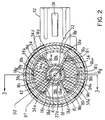
- Figure 2 is a sectional view taken along lines 2-2 of Figure 1 of the coil bobbin with arcuate permanent magnet segments frictinally fit and heat staked in pockets in the bobbin.
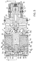
- Figure 3 is a longitudinal cross-section taken along lines 3-3 of the proportional variable force solenoid fluid control valve.
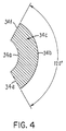
- Figure 4 is a side elevation of a permanent magnet segment.
- Referring to Figure 1, a proportional variable force solenoid
fluid control valve 10 includesvalve member 12 and associated valve components disposed in a valve ornozzle housing 19a and a solenoid 14 disposed in a generallycylindrical solenoid housing 19b in a manner to provide a fluid control valve of the general type described in the Najmolhoda U.S. Patent 4,988,074 of common assignee herewith, the teachings of which are incorporated herein by reference. Thevalve housing 19a can be made of aluminum, while thesolenoid housing 19b can comprise steel or other ferromagnetic material pursuant to U.S. Patent 4,988,074. The valve housing 19a andsolenoid housing 19b can be joined together by tabs T, Fig. 3, of thesolenoid housing 19b crimped over an annular shoulder of thevalve housing 19a as shown in U.S. Patent 4,988,074, or formed as a single, common housing, pursuant to Najmolhoda U.S. Patent 5,611,370 with the common housing made of a substantially non-magnetic material with little or no magnetic permeability, the teachings of which patents are incorporated herein by reference to this end. - A material particularly suited for such a common or single housing comprises aluminum and its alloys or thermoplastic formed by casting or injection molding to required housing configuration to receive the
valve member 12 and the solenoid 14. The common housing will include a housing section or region for enclosing the solenoid 14 and a nozzle housing section or region for enclosing thevalve 12 and associated valve components. - Referring to Figure 1, the solenoid 14 is disposed in the
solenoid housing 19b (or solenoid housing section of the common housing embodiment) and includes anelectromagnetic solenoid coil 16 wound about a cylindrical surface of moldedplastic bobbin 18 which has a cylindricallyshaped bore hole 20 through the longitudinal axis thereof. Thebobbin 18 is made of glass filled thermoplastic. An axially elongated, generallycylindrical armature 22 formed of a ferromagnetic material (e.g. steel) is suspended within thebore hole 20 of theplastic bobbin 18 by a thin lowspring rate spring 24 mounted at a rear,outermost end 22a of the armature. - The
plate spring 24 is of the type described in the aforementioned Najmolhoda U.S. Patent 4,988,074, the teachings of which are incorporated herein by reference. That is, the spring plate is formed from very thin non-magnetic austenitic stainless steel, such as full hard austenitic stainless steel, which provides a very low rate spring for the spring configuration shown in Fig. 5 of the aforementioned '074 patent. The inner periphery of theplate spring 24 is mounted by a non-ferrous (e.g. half hard brass) annular armaturespring retainer member 25 mounted to the rear,outer end 22a of thearmature 22 so as to suspend thearmature 22 for free axial longitudinal movement within thebobbin 18. The opposite front,inner end 22b of the armature can be supported by a similar optional plate spring (not shown) or, the plate spring 26 may be omitted from the embodiment of Figure 1 with theinner end 22b of thearmature 22 unsupported, except by the axial periphery of adamping member 25 received indamping chamber 80 as described below. - The outer periphery of the
plate spring 24 is mounted between the radially enlarged annular end flange orshoulder 18r of thecoil bobbin 18 and an opposing annular end of valve housing cap orclosure 46 made of aluminum alloy (e.g. Al alloy 6061 T6). Thesolenoid housing 19a includes an annular end flange 19e overlying the cap orclosure 46 as shown with a Bellvellewave washer 47 therebetween to accommodate stack up tolerances. - As shown in Figure 1, a
damping member 25 on theinner end 22b of thearmature 22 engages asteel ball valve 38.Ball valve 38 cooperates with anannular valve seat 21a on a ball valve cage insert 21 pressed in the valve ornozzle housing 19a. Theball valve 38 andvalve seat 21a define a fluid diverting valve for diverting fluid toexhaust ports 74 in a manner described below. An optional flux washer W can be provided in a recess inbobbin 18 pursuant to the aforementioned U.S. Patent 4988,074, incorporated herein by reference, to concentrate electromgantic flux at the inner end of the armature. - In accordance with an embodiment of the invention, a plurality of axially magnetized permanent magnet segments 34 (two segments shown for illustration only) each segment having an inner
arcuate magnet surface 34a facing thearmature 22 are present to collectively provide a permanent magnetic field that cooperates with the electromagnetic field of theenergized coil 16 to move thearmature 22. Thepermanent magnet segments 34 are disposed about the outer cylindrical periphery orsurface 22e of thearmature 22 in respective circumferentially spaced apart, axially extendingpockets 18a of thecoil bobbin 18 in a common transverse plane relative to the longitudinal axis A of movement of thearmature 22 andbobbin bore hole 20. Themagnet segments 34 are selected in number and circumferential length or extent of innerarcuate surfaces 34a extent to collectively encompass or overlie less than 100% of the outer cylindrical periphery orsurface 22e of thearmature 22 when viewed in cross-section transverse to the longitudinal axis A, see Figure 2. Two, three, four, ormore magnet segments 34 may be present to this end. Preferably, the innerarcuate surfaces 34a of thepermanent magnet segments 34 collectively encompass or overlie at least about 67 % of theouter armature surface 22e when viewed in transverse cross-section. More preferably, the innerarcuate surfaces 34a collectively encompass or overlie about 70 to about 80 % of theouter armature surface 22e of the armature when viewed in transverse cross-section, Figure 2. - Referring to Figures 2 and 4, each
permanent magnet segment 34 includes inner arcuate face orsurface 34a facing theouter armature surface 22e, which is formed collectively by adjacent coextensive outer surfaces of thearmature 22 andarmature spring retainer 25. Eachsegment 34 also includes an outer arcuate face orsurface 34b, first and second axial side faces 34c, 34d, and first and second radially extending end faces 34e, 34f to from a generally C-shaped magnet segment. Each segment is axially magnetized between side faces 34a, 34d as indicated by the "N" and "S" magnetic pole indicia in Figure 3 such that the axial direction of magnetization is generally parallel with the longiditudinal axis A of thearmature 22. - The radially extending end faces 34e, 34f are circumferentially spaced from respective end faces of an
adjacent magnet segment 34. The end faces 34e, 34f, when viewed in transverse cross-section, are disposed in radial planes that intersect the center of thearmature 22 which lies on longitudnal axis A. In the embodiment shown in Figures 1-4, the radially extending end faces 34e, 34f define therebetween an included angle of 120 degrees about the center of thearmature 22, although other angles in the range of about 90 to about 140 degrees can be used in practicing the invention. Exemplary arc lengths of the innerarcuate face 34a and outerarcuate face 34b for the aforementioned included angle of 120 degrees of Figure 4 are 0.336 inch and 0.671 inch, respectively, with the lengths of the end faces each being 0.160 inch. The inner arcuate faces 34a of each magnet segment typcially are spaced a radial distance (nominal) of about 0.0205 inch from theouter surface 22e of thearmature 22. For example, an outer diameter D1 of thearmature surface 22e can be 0.280 inch, while the inner diameter D2 of the inner arcuatemagnet segment surface 34a can be 0.321 inch. - The
coil bobbin 18 pursuant to an embodiment of the invention includes respective axially extending, generally trapezoidal shaped (in end elevation) pockets 18a to receive eachpermanent magnet segment 34 with the axial side faces 34c, 34d oriented generally perpendicular to the longitudinal axis A of the armature. Eachpocket 18a is defined by an innerarcuate opening 18b, an outerarcuate wall 18c and first and second radially extendingend walls pocket end wall 18f extending generally perpendicular to the longiudinal axis A. The coil bobbin also includes an annularcircumferential end groove 18j adjacentannular shoulder 18r. - Between the
pockets 18a are disposed empty axially extending, generally trapezoidal shaped (in end elevation) recesses 18k. Eachrecess 18k includes innerarcuate wall 18w and outer arcuate wall that comprises portions of continuouscircumferential walls 18m of the bobbin that also defines the outerarcuate walls 18c of thepockets 18a as evident from Figure 2. The radially extending walls of eachempty recess 18k are shared with theadjacent pocket 18a. - Each
permanent magnet segment 34 is confined in itsown pocket 18a and separated fromadjacent magnet segments 34 by theempty recesses 18k and from thearmature 22 by the innerarcuate opening 18b of the pocket. Eachpermanent magnet segment 34 preferably is frictionally confined in eachpocket 18a by virtue of each outerarcuate face 34b and radially extendingend face posts pocket 18a integral therewith (e.g. molded) with the outerarcuate wall 18c and radially extendingend walls magnet segment 34 is inserted into the pocket. Ahemispherical recess 18p preferably is provided in theaxial end wall 18f of each pocket behind themagnet segment 34, in Figure 2, proximate the locatingposts posts magnet segment 34 is frictionally inserted into each pocket so that the shavings do not mis-orient the magnet segment in its pocket. - The
permanent magnet segments 34 are formed of rare earth permanent magnet material, such as Sm-Co or preferably Nd2Fe14B, permitting use of a reduced size magnet segments that result in a compact solenoid. The axially magnetizedpermanent magnet segments 34 collectively produce a permanent magnetic field that substantially axially saturates thearmature 22 even in the absence of electrical current to thecoil 16. Thus, a relatively smaller magnetic field is required to move thearmature 22 between the axial position shown in Figure 1 corresponding to a valve closed position (whereball valve 38 is seated on thevalve seat 21a) and an axial position to the left in Figure 1 corresponding to a valve open position (whereball valve 38 is unseated from thevalve seat 21a). - In a method embodiment of the invention, the
permanent magnet segments 34 are each positioned in arespective pocket 18a of thecoil bobbin 18 so as to be disposed about the periphery of thebore hole 20 with the innerarcuate surfaces 34a collectively overlying less than 100% of thebore hole 20 and thus thearmature surface 22a when viewed in cross-section transverse to the longitudinal axis A. Preferably, thepermanent magnet segments 34 are inserted into each pocket such that there is frictional engagement of the outerarcuate face 34b and first and second radially extending end faces 34e, 34f of eachmagnet segment 34 with axially extending locatingposts recesses 18p in the bobbinaxial end wall 18f proximate the locating posts in a manner that the shavings do not mis-orient themagnet segment 34 in the pocket. After thepermanent magnet segments 34 are positioned in therespective pockets 18a, they are heat stacked therein by heating and deforming portions ofradial end walls bobbin 18 asheat stake tabs 18t over the magnet segments, Figures 1 and 3. - The
ball valve 38 is received and confined laterally in a flat-sided recess or cage machined or otherwise formed in thestainless steel insert 21 between the inner end of thearmature 22 and thevalve seat 21a. In this valve arrangement, theball valve 38 is biased bycoil spring 42 against thearmature end 22b and follows movement of thearmature 22 in a direction toward or away from thevalve seat 21a by virtue of the fluid pressure on the ball valve and by virtue being captured in the cage 21b. - Coil compression spring 42 (spring biasing means) is trapped in a cylindrical armature counterbore between the
axial armature end 22a and a centralaxially extending projection 46a of the valve housing cap orclosure 46. Theprojection 46a receives thecoil spring 42 with the end of thespring 42 engaging the inner surface or wall of thecap 46. Thearmature 22 is biased to the valve closed position by thecoil spring 42 when thesolenoid coil 16 is deenergized. The cap orclosure 46 includes a cylindrical outer surface received ina a cylndrical counterbore of thebobbin 18 totrap spring 24 as shown. - A
plastic connector body 52 is mounted on thebobbin 18 and exits thesolenoid housing 19b via asuitable opening 19f therein. Electrical contacts 54 (only one shown) extend through thebobbin 18 and through apertures in theconnector body 52. Suchelectrical contacts 54 are shown in the aforementioned Najmolhoda U.S. Patent 4,988,074. The ends of theelectrical contacts 54 are connected to the wires of theelectromagnetic coil 16 for receiving an electrical current signal from a variable current source (not shown). - The
armature damping member 25 includes a generally flat-sided disk shapedsection 25b formed on theinner armature end 22b. Thearmature damping member 25 comprises the ferromagnetic armature material, such as steel, to provide an improved magnetic flux carrier to direct the magnetic flux directly into thearmature end 22b, while reducing size of the solenoid unit. - The
disk end section 25b includes a cylindrical outerperipheral surface 25c that cooperates with cylindrical dampingchamber 80 disposed in the valve ornozzle housing 19a to reduce or dampen pressure oscillations resulting from electrical, mechanical, and/or hydraulic noise in the controlled fluid system or circuit; i.e. the fluid system or circuit, such as an automatic transmission circuit, controlled byvalve 12 as described in copending application Serial No. 08/978 257, and entitled Proportional Variable Force Solenoid Control Valve With mature Damping, of common assignee herewith. To this end, there is a controlled clearance between the outer cylindrical,peripheral surface 25c of the dampingmember 25 and thechamber wall 80a. The dampingchamber 80 is machined or otherwise formed in the valve ornozzle housing 19a and communicates with the exhaust ports 74 (two shown with two additional exhaust ports not shown extending into and out of the plane of the drawing). - In operation in an automatic trnasmission application where the control valve is fully immersed in hydraulic trnasmission fluid, the damping
chamber 80 typically will have predominantly hydraulic fluid therein, although some air may be present in the dampingchamber 80. - The cross-sectional area of the damping
member 25 and the clearance between thesurface 25c and the cooperatingwall 80a of the dampingchamber 80 are selected effective to reduce or damp pressure oscillations resulting from noise in the controlled fluid system or circuit, which pressure oscillations can result in non-linear valve response performance. An exemplary cross-sectional area of thedisk section 25b (cross-sectional area calculated using the outer diameter of damping member 25) can be 0.039 inch2 (0.54 inch outer diameter of damping member disk section). For this exemplary cross-sectional area of the dampngmember 25, an exemplary radial clearance of approximately 0.005 inch can be provided between thedisk surface 25c and thechamber wall 80a for the proportional variable force solenoid fluid control valve shown in Figure 1 adapted for use in a hydraulic automatic transmission application for controlling a gear shifting hydraulic circuit. More generally, the aforementioned radial clearance can be in the range of 0.004 to 0.0055 inch for a disk section outer diameter in the range of 0.54 to 0.542 inch and axial length ofsurface 25c in the range of 0.070 to 0.074 inch in a damping chamber having inner diameter of 0.550 to 0.551 inch to provide a damping area in the range of 0.0003 to 0.0004 inch2. - In effect, the damping
chamber 80 and the dampingmember 25 provide a trapped volume of fluid comprising predominantly hydraulic fluid which must be moved through the restricted clearance area between thesurface 25c and thewall 80a and in doing so reduces or damps pressure oscillations resulting from electrical, mechanical, and/or hydraulic noise in the controlled fluid system or circuit. - The valve or
nozzle housing 19a includes alongitudinal passageway 66 having a generally cylindrical configuration for receiving an aluminum alloy spool 67 (e.g. Al alloy 6262) which is received in thepassageway 66 in a close fit, sliding manner at spool end regions for axial reciprocable movement. - The
housing 19a is disposed in a bore or chamber (not shown) in a cast aluminum transmission body (not shown) or other fluid control system. Outer O-ring seals S1, S2 on thevalve housing 19a seal on the transmission housing and separate the supply and control lines or conduits (not shown) of the transmission hydraulic circuit. - The
valve housing 19a includes a pressurized fluid supply orinlet port 72, a plurality ofcontrol ports 83, a plurality offirst exhaust ports 81 associated with the control ports, and a plurality ofsecond exhaust ports 74 associated with theball valve 38. Thevalve housing 19a includes the dampingchamber 80 communicated with theball valve 38 and in turn therespective exhaust ports 74. These ports can be cast, machined or otherwise formed in thevalve housing 19a. Thecontrol ports 83,exhaust ports 81, andexhaust ports 74 are spaced circumferentially about thenozzle section 19a. Typically, twocontrol ports 83, fourexhaust ports 81, and fourexhaust ports 74 are provided on thevalve housing 19a. A tubular fluid filter screen assembly FSA is held on thenozzle housing 19a byretainer 75 and sealed thereto by O-ring 77. The assembly includes filter screens F overlying the inlet andcontrol ports - The
inlet port 72 communicates with anannular chamber 73 that, in turn, is in communication with a radial fluid passage 67a of thespool 67. Passage 67a communicates with a longitudinalcentral passage 67b of thespool 67 having anorifice plug 67h press fit therein. - The
slidable spool valve 67 is disposed in thevalve housing 19a to provide a two stage operation wherein, in the first stage, pressurized fluid is supplied to the inlet orsupply port 72 with the end 67c of the spool valve abutted against housing stop end wall (proximate insert 21) as shown in Figure 1 as biased byspring 68 and with theball valve 38 seated against thevalve seat 21a with no electrical current to thecoil 16.Spring 68 abuts anend closure 69. As a result, the entering fluid flow is caused to bypass thecontrol ports 83 and instead is directed to flow throughspool passages 67a, 67b and orifice plug 67h to the axial fluid passage ofvalve insert 21. Theball valve 38 initially is seated on thevalve seat 21a by virtue of the force of thecoil spring 42. The position of thespool valve 67 corresponding to a minimum fluid flow spool valve position relative to thecontrol ports 83 occurs when the annularspool control land 67e is not communicated to theinlet port 72. However, once the fluid reachesvalve seat 21, fluid pressure increases to a level that moves thespool valve 67 to the right in Figure 1 againstspring 68 sufficiently to communicate theannular control land 67e to theinlet port 72 withexhaust ports 81 closed. This position of thespool valve 67 corresponds to a maximum fluid flow spool valve position relative to thecontrol ports 83 wherein the annular spool control chamber is communicated to theinlet port 72. Commnication of thespool control land 67e with theinlet port 72 also communicates theend 67d of thespool valve 67 to thecontrol pressure port 83 via thepassage 67g. Thus, when the steady state flow conditions are realized, the opposite ends of thespool valve 67 are subjected to equal fluid pressure. - Thereafter, a second stage of operation involves controlling the fluid flow through the
control ports 83 by spool valve movement between the aforementioned minimum and maximum flow spool positions. Movement of the spool valve is controlled by diverting fluid from thevalve seat 21a out through theexhaust ports 74 to vary fluid pressure in a linear proportional manner. For example, electrical current is supplied to thecoil 16 via thecontacts 54 to create an electromagnetic field which, in addition to the permanent magnet field ofpermanent magnet segments 34 and force of fluid pressure on theball valve 38, overcomes thecoil spring 42 and slight force ofspring plate 24 to move thearmature 22 in a linear proportional manner to the current level applied tocoil 16. Since theball valve 38 moves with thearmature 22, theball valve 38 will open in linear proportional manner to the current applied to thecoil 16 and divert fluid out of theexhaust ports 74 to unbalance fluid pressure on the spool valve member ends to control the spool valve position in linear proportional manner between the aforementiond minimum and maximum fluid flow spool positions relative to thecontrol ports 83 andexhaust ports 81 of thevalve housing 19a. This provides a controlled fluid flow out of thecontrol ports 83 in direct proportion to the opening of theball valve 38 in accordance with linear movement of thearmature 22 which, in turn, is directly proportional to the amount of electrical current supplied to thecoil 16 of the solenoid 14. - Such axial spool movement as described herebove provides a negative gain mode of fluid flow control wherein there is a linear decrease in fluid pressure at the
control ports 80 in proportion to an increase in electrical current to thecoil 16. However, a positive gain mode of fluid flow control also can be achieved by the proportional variable forcefluid control valve 10 described by reversing the flow of electrical current in thecoil 16 and by introducing supply pressure through theinlet port 72 with theball valve 38 in the full open position as determined by the position of thearmature 22 with current flowing in thecoil 16 as described in aforementioned U.S. Patent 5,611,370. - Regardless of whether the proportional variable force
solenoid control valve 10 is operated in a positive or negative gain mode, thearmature disk 25 and dampingchamber 80 will cooperate to reduce or dampen fluid pressure oscillations resulting from electrical, mechanical, and/or hydraulic noise in the controlled fluid system or circuit, which pressure oscillations, in turn, can result in non-linear valve response behavior. In an electronically controlled automobile transmssion application, electromechanical noise in the controlled system or circuit can originate in the transmission control module (e.g. a chopped pulse width control signal) and oscillations of the clutch or shift valves in the transmission body and produce fluid pressure oscillations and a non-linear valve response. - Although certain preferred embodiments of the proportional variable force solenoid valve and fluid control device for an electronic transmission of the invention have been shown and described in detail, it should be understood that variations or modifications may be made without departing from the spirit or scope of the present invention.
Claims (26)
- A proportional variable force solenoid valve for controlling the pressure of a fluid in a fluid control system, comprising a housing having therein a solenoid coil disposed on a coil bobbin, an armature movable in response to electrical current applied to the solenoid coil, means for biasing the armature in a direction to establish a valve fluid pressure response to solenoid coil current, and a plurality of axially magnetized permanent magnet segments each having an inner arcuate magnet surface facing the armature and collectively providing a permanent magnetic field that cooperates with the electromagnetic field of the energized coil to move the armature, said permanent magnet segments being disposed about the periphery of the armature in respective peripherally spaced apart pockets of the coil bobbin in a common transverse plane relative to the longitudinal axis of movement of the armature, said magnet segments being selected in number and inner arcuate surface length to collectively encompass or overlie less than 100% of the peripheral surface of the armature when viewed in cross-section transverse to the longitudinal axis.
- The control valve of claim 1 wherein the inner arcuate surface lengths of said permanent magnet segments collectively encompass at least about 67% when viewed in transverse cross-section.
- The control valve of claim 2 wherein the inner arcuate surface lengths of said permanent magnet segments collectively encompass about 70% to about 80% of the peripheral surface of the armature when viewed in transverse cross-section.
- The control valve of claim 1 wherein each permanent magnet segment includes an inner arcuate surface facing the armature and an outer arcuate surface, first and second axial side faces, and first and second radially extending end faces to form a generally C-shaped magnet segment, each segment being axially magnetized between said side faces.
- The control valve of claim 4 wherein the radially extending end faces are cicumferentially spaced from respective end faces of an adjacent magnet segment, said end faces, when viewed in transverse cross-section, being disposed in radial planes that intersect the center of the armature.
- The control valve of claim 4 wherein the coil bobbin includes respective axially extending pockets to receive each permanent magnet segment with the axial side faces oriented generally perpendicular to the longitudinal axis of movement of the armature, each pocket being defined by an inner arcuate opening, an outer arcuate wall and first and second radially end walls and including an open outer axial end through which a respective magnet segment is inserted into the pocket and an inner axial end closed by an axial pocket wall extending generally perpendicular to the longiudinal axis.
- The control valve of claim 6 wherein each magnet segment is confined in its own pocket and separated from adjacent magnet segments by the radially extending end walls of the pocket and from the armature by the inner arcuate opening of the pocket.
- The control valve of claim 7 wherein each magnet segment is frictionally confined in each pocket.
- The control valve of claim 8 wherein each permanent magnet segment is frictionally confined by the radially extending end faces of the magnet segment frictionally engaging first and second axially extending locating posts provided in each pocket proximate the radially extending end walls when the segment is inserted into the pocket.
- The control valve of claim 9 wherein a recess is provided in the axial wall of each pocket proximate the junction of the axial wall and each radially extending end wall to receive plastic shavings that are removed from the locating posts as the magnet segment is frictionally inserted into each pocket so that the shavings do not mis-orient the magnet segment in the pocket.
- A coil bobbin and permanent magnet assembly for a solenoid, comprising a surface on which a solenoid coil is disposed about a longitudinal armature-receiving bore and a plurality of circumferentially spaced apart, axially extending pockets in the coil bobbin disposed in a common transverse plane relative to the longitudinal axis of said bore, and a plurality of axially magnetized permanent magnet segments each having an inner arcuate magnet surface facing said bore and collectively providing a permanent magnetic field that cooperates with an electromagnetic field of said coil, said permanent magnet segments being disposed in said pockets about the periphery of the bore and being being selected in number and inner arcuate surface length to collectively overlie less than 100% of said bore when viewed in cross-section transverse to the longitudinal axis.
- The assembly of claim 11 wherein the inner arcuate surface length of said permanent magnet segments collectively encompass about 70% to about 80% of said bore when viewed in transverse cross-section.
- The assembly of claim 11 wherein each permanent magnet segment includes an inner arcuate surface facing the armature and an outer arcuate surface, first and second axial side faces, and first and second radially extending end faces to form a generally C-shaped magnet segment, each segment being axailly magnetized between said side faces.
- The assembly of claim 13 wherein the radially extending end faces are cicumferentially spaced from the end faces of an adjacent magnet segment, said end faces, when viewed in transverse cross-section, being disposed in radial planes that intersect the center of said bore.
- The assembly of claim 13 wherein the coil bobbin includes respective axially extending pockets to receive each permanent magnet segment with the axial side faces oriented generally perpendicular to the longitudinal axis of movement of the armature, each pocket being defined by an inner arcuate opening, an outer arcuate wall and first and second radially end walls and including an open outer axial end through which a respective magnet segment is inserted into the pocket and an inner axial end closed by an axial pocket wall extending generally perpendicular to the longitudinal axis.
- The assembly of claim 13 wherein each magnet segment is confined in its own pocket and separated from adjacent magnet segments by the end walls of the pocket and from the armature by the inner arcuate opening of the pocket.
- The assembly of claim 16 wherein each magnet segment is frictionally confined in each pocket.
- The assembly of claim 17 wherein each permanent magnet segment is frictionally confined by the radially extending end faces of the magnet segment frictionally engaging first and second axially extending locating posts provided in each pocket proximate the radially extending end walls when the segment is inserted into the pocket.
- The assembly claim 18 wherein a recess is provided in the axial wall of each pocket behind the magnet segment proximate the junction of the axial wall and each radially extending end wall to recieve plastic shavings that are removed from the locating posts as the magnet segment is frictionally inserted into each pocket so that the shavings do not mis-orient the magnet segment in the pocket.
- A coil bobbin, comprising a surface on which a solenoid coil is disposed about a longitudinal armature-receiving bore and a plurality of circumferentially spaced apart, axially extending magnet-receiving pockets in the coil bobbin disposed in a common transverse plane relative to the longitudinal axis of said bore.
- The bobbin of claim 20 wherein each pocket is defined by an inner arcuate opening, an outer arcuate wall and first and second radially end walls and including an open outer axial end through which a respective axially magnetized magnet segment can be inserted into the pocket and an inner axial end closed by an axial pocket wall extending generally perpendicular to the longiudinal axis.
- The bobbin of claim 21 wherein each pocket further includes first and second axially extending locating posts provided in each pocket proximate the radially extending end walls.
- The bobbin of claim 22 wherein a recess is provided in the axial wall of each pocket proximate the junction of the axial wall and each radially extending end wall to receive plastic shavings that are removed from the locating posts as a magnet segment is frictionally inserted into each pocket so that the shavings do not mis-orient the magnet segment in the pocket.
- A method of assembling a solenoid having an armature and a wire coil disposed on a bobbin having a longitudinal armature-receiving bore, comprising forming a plurality of peripherally spaced apart pockets in the coil bobbin disposed in a common transverse plane relative to the longitudinal axis of said bore, providing a plurality of axially magnetized permanent magnet segments each having an inner arcuate magnet surface for facing said bore, and positioning said permanent magnet segments in respective pockets about the periphery of the bore such that the inner arcuate surfaces collectively overlie less than 100% of said bore when viewed in cross-section transverse to the longitudinal axis.
- The method of claim 24 includng frictionally engaging axially extending end surfaces of each magnet segment with axially extending end walls of a respective pocket as each magnet segment is postioned in each pocket.
- The method of claim 24 including collecting any shavings removed from said bobbin in a recess in said bobbin as each magnet segment is postioned in each pocket in a manner that the shavings do not mis-orient said magnet segment in said pocket.
Applications Claiming Priority (2)
| Application Number | Priority Date | Filing Date | Title |
|---|---|---|---|
| US63963 | 1998-04-21 | ||
| US09/063,963 US6179268B1 (en) | 1998-04-21 | 1998-04-21 | Proportional variable force solenoid control valve with segmented permanent magnet |
Publications (3)
| Publication Number | Publication Date |
|---|---|
| EP0952506A2 true EP0952506A2 (en) | 1999-10-27 |
| EP0952506A3 EP0952506A3 (en) | 2001-01-10 |
| EP0952506B1 EP0952506B1 (en) | 2004-10-06 |
Family
ID=22052640
Family Applications (1)
| Application Number | Title | Priority Date | Filing Date |
|---|---|---|---|
| EP99107693A Expired - Lifetime EP0952506B1 (en) | 1998-04-21 | 1999-04-17 | Proportional variable force solenoid control valve with segmented permanent magnet |
Country Status (6)
| Country | Link |
|---|---|
| US (1) | US6179268B1 (en) |
| EP (1) | EP0952506B1 (en) |
| JP (1) | JP4440367B2 (en) |
| KR (1) | KR100523790B1 (en) |
| CA (1) | CA2269302C (en) |
| DE (1) | DE69920794T2 (en) |
Cited By (1)
| Publication number | Priority date | Publication date | Assignee | Title |
|---|---|---|---|---|
| EP3141736A1 (en) * | 2015-09-09 | 2017-03-15 | Continental Automotive GmbH | Power group for a fuel injector and fuel injector |
Families Citing this family (31)
| Publication number | Priority date | Publication date | Assignee | Title |
|---|---|---|---|---|
| EP1336785B1 (en) * | 2002-02-19 | 2006-05-10 | SCHROTT, Harald | Bistable electromagnetic valve |
| US6641895B1 (en) | 2002-12-06 | 2003-11-04 | Adams Mfg. Corp. | Heat staked magnet in multi-piece housing |
| US6791442B1 (en) * | 2003-11-21 | 2004-09-14 | Trombetta, Llc | Magnetic latching solenoid |
| US7007915B2 (en) * | 2004-03-10 | 2006-03-07 | Masco Corporation Of Indiana | Low energy fluid actuator control element |
| US7458395B2 (en) * | 2004-06-07 | 2008-12-02 | Borgwarner Inc. | Low leak poppet solenoid |
| US6968860B1 (en) | 2004-08-05 | 2005-11-29 | Masco Corporation Of Indiana | Restricted flow hands-free faucet |
| US7819131B2 (en) * | 2005-02-14 | 2010-10-26 | Cameron International Corporation | Springless compressor valve |
| US7673597B2 (en) | 2005-12-09 | 2010-03-09 | Saturn Electronics & Engineering, Inc. | Hydraulic fluid passage with particle gettering magnet |
| US8127791B2 (en) | 2005-12-21 | 2012-03-06 | Saturn Electronics & Engineering, Inc. | Solenoid operated fluid control valve |
| US8839819B2 (en) * | 2006-09-26 | 2014-09-23 | Borgwarner Inc. | Direct-acting pilot pressure control solenoid |
| US20080169439A1 (en) * | 2006-12-18 | 2008-07-17 | Borgwarner Inc. | Integrated two-stage low-leak control valve |
| US8387644B2 (en) * | 2007-02-09 | 2013-03-05 | Saturn Electronics & Engineering, Inc. | Solenoid operated fluid control valve |
| US20080218158A1 (en) * | 2007-03-07 | 2008-09-11 | Carlson Joseph D | Rotary position sensor |
| US7552719B2 (en) * | 2007-12-04 | 2009-06-30 | Caterpillar Inc. | Solenoid assembly having slotted stator |
| US8172060B2 (en) * | 2008-04-02 | 2012-05-08 | Saturn Electonics & Engineering, Inc. | Dynamic pressure control system with solenoid valve command current trimming |
| AT507087B1 (en) * | 2008-12-05 | 2010-02-15 | Siemens Vai Metals Tech Gmbh | METHOD AND DEVICE FOR THE SEMI-ACTIVE REDUCTION OF PRESSURE VIBRATIONS IN A HYDRAULIC SYSTEM |
| AT507088B1 (en) * | 2008-12-05 | 2010-02-15 | Siemens Vai Metals Tech Gmbh | METHOD AND DEVICE FOR THE ACTIVE SUPPRESSION OF PRESSURE VIBRATIONS IN A HYDRAULIC SYSTEM |
| JP5409814B2 (en) | 2009-02-17 | 2014-02-05 | シーティーエス・コーポレーション | Rotary position sensor |
| US8573559B1 (en) | 2012-04-18 | 2013-11-05 | Husco Automotive Holdings, LLC | Control valve with area independent pressure sensing |
| US8534639B1 (en) | 2012-04-18 | 2013-09-17 | HUSCO Automotive Holdings, Inc. | Solenoid valve with a digressively damped armature |
| CN103267160B (en) * | 2013-05-26 | 2015-02-18 | 魏伯卿 | Normally-opened and normally-closed type electric control valve |
| US9368266B2 (en) | 2014-07-18 | 2016-06-14 | Trumpet Holdings, Inc. | Electric solenoid structure having elastomeric biasing member |
| RU2624926C1 (en) * | 2015-09-14 | 2017-07-11 | Государственное учреждение высшего профессионального образования "Белорусско-Российский университет" | Proportional valve of management of hydromechanical transfer frequencies |
| CN108291456B (en) | 2015-11-17 | 2021-03-12 | 舍弗勒技术股份两合公司 | Electromagnetic adjusting device |
| EP3261102A1 (en) | 2016-06-23 | 2017-12-27 | Rain Bird Corporation | Universal solenoid |
| US10980120B2 (en) | 2017-06-15 | 2021-04-13 | Rain Bird Corporation | Compact printed circuit board |
| US11503782B2 (en) | 2018-04-11 | 2022-11-22 | Rain Bird Corporation | Smart drip irrigation emitter |
| JP7434741B2 (en) * | 2019-07-18 | 2024-02-21 | オムロン株式会社 | Vibration generator for push button switch, push button switch |
| JP7451897B2 (en) * | 2019-07-18 | 2024-03-19 | オムロン株式会社 | Vibration generator |
| US11721465B2 (en) | 2020-04-24 | 2023-08-08 | Rain Bird Corporation | Solenoid apparatus and methods of assembly |
| CN114017410B (en) * | 2021-11-03 | 2022-06-17 | 中国重型机械研究院股份公司 | High-stain-resistance ultrahigh-frequency-response digital hydraulic switch valve and working method |
Citations (2)
| Publication number | Priority date | Publication date | Assignee | Title |
|---|---|---|---|---|
| US4988074A (en) | 1988-05-17 | 1991-01-29 | Hi-Ram, Inc. | Proportional variable force solenoid control valve |
| US5611370A (en) | 1994-11-10 | 1997-03-18 | Saturn Electronics & Engineering, Inc. | Proportional variable force solenoid control valve and transmission fluid control device |
Family Cites Families (10)
| Publication number | Priority date | Publication date | Assignee | Title |
|---|---|---|---|---|
| GB1419262A (en) * | 1972-11-02 | 1975-12-24 | Fluid Devices Ltd | Electromagnetic actuator |
| US3977436A (en) * | 1972-11-02 | 1976-08-31 | Fluid Devices Limited | Bi-stable valve apparatus |
| US4217507A (en) * | 1979-01-08 | 1980-08-12 | The Singer Company | Linear motor |
| DE3271375D1 (en) * | 1982-08-20 | 1986-07-03 | Burkert Gmbh | Magnetic-impulse valve with a permanent magnetic latch mechanism without changeable magnetisation |
| US4946009A (en) * | 1989-04-12 | 1990-08-07 | Applied Power, Inc. | Electromagnetic valve utilizing a permanent magnet |
| GB2258566B (en) * | 1991-08-07 | 1994-12-21 | Johnson Electric Sa | Permanent magnet rotor |
| DE4215145A1 (en) * | 1992-05-08 | 1993-11-11 | Rexroth Mannesmann Gmbh | Linear control motor esp. as part of control or regulating valve - has control coils adjacent permanent magnets inside tubular housing with movable armature |
| DE4403420A1 (en) * | 1994-02-04 | 1995-08-10 | Fluid Systems Partners S A | Linear electromagnetic drive for control elements |
| US5661446A (en) * | 1995-06-07 | 1997-08-26 | Mts Systems Corporation | Electromagnetic actuator |
| US5845667A (en) * | 1996-12-19 | 1998-12-08 | Saturn Electronics & Engineering, Inc. | Single stage variable force solenoid pressure regulating valve |
-
1998
- 1998-04-21 US US09/063,963 patent/US6179268B1/en not_active Expired - Lifetime
-
1999
- 1999-04-17 EP EP99107693A patent/EP0952506B1/en not_active Expired - Lifetime
- 1999-04-17 DE DE69920794T patent/DE69920794T2/en not_active Expired - Lifetime
- 1999-04-19 CA CA002269302A patent/CA2269302C/en not_active Expired - Fee Related
- 1999-04-20 KR KR10-1999-0013926A patent/KR100523790B1/en not_active IP Right Cessation
- 1999-04-20 JP JP11165199A patent/JP4440367B2/en not_active Expired - Lifetime
Patent Citations (2)
| Publication number | Priority date | Publication date | Assignee | Title |
|---|---|---|---|---|
| US4988074A (en) | 1988-05-17 | 1991-01-29 | Hi-Ram, Inc. | Proportional variable force solenoid control valve |
| US5611370A (en) | 1994-11-10 | 1997-03-18 | Saturn Electronics & Engineering, Inc. | Proportional variable force solenoid control valve and transmission fluid control device |
Cited By (2)
| Publication number | Priority date | Publication date | Assignee | Title |
|---|---|---|---|---|
| EP3141736A1 (en) * | 2015-09-09 | 2017-03-15 | Continental Automotive GmbH | Power group for a fuel injector and fuel injector |
| WO2017041978A1 (en) * | 2015-09-09 | 2017-03-16 | Continental Automotive Gmbh | Power group for a fuel injector and fuel injector |
Also Published As
| Publication number | Publication date |
|---|---|
| CA2269302A1 (en) | 1999-10-21 |
| DE69920794T2 (en) | 2006-02-23 |
| EP0952506A3 (en) | 2001-01-10 |
| CA2269302C (en) | 2008-02-05 |
| US6179268B1 (en) | 2001-01-30 |
| KR100523790B1 (en) | 2005-10-25 |
| KR19990083324A (en) | 1999-11-25 |
| JP4440367B2 (en) | 2010-03-24 |
| DE69920794D1 (en) | 2004-11-11 |
| EP0952506B1 (en) | 2004-10-06 |
| JPH11336932A (en) | 1999-12-07 |
Similar Documents
| Publication | Publication Date | Title |
|---|---|---|
| EP0952506B1 (en) | Proportional variable force solenoid control valve with segmented permanent magnet | |
| US5984259A (en) | Proportional variable force solenoid control valve with armature damping | |
| US8127791B2 (en) | Solenoid operated fluid control valve | |
| EP0989345B1 (en) | Single stage variable force solenoid pressure regulating valve | |
| CA2161313C (en) | Proportional variable force solenoid control valve and transmission fluid control device | |
| US8186317B2 (en) | Hydraulic fluid passage with particle gettering magnet field of the invention | |
| EP0849514A2 (en) | Single stage variable force solenoid pressure regulating valve | |
| US6581634B2 (en) | Solenoid control valve with particle gettering magnet | |
| KR100518716B1 (en) | Proportional Variable Force Solenoid Control Valve with Armature Damping |
Legal Events
| Date | Code | Title | Description |
|---|---|---|---|
| PUAI | Public reference made under article 153(3) epc to a published international application that has entered the european phase |
Free format text: ORIGINAL CODE: 0009012 |
|
| AK | Designated contracting states |
Kind code of ref document: A2 Designated state(s): DE FR GB IT |
|
| AX | Request for extension of the european patent |
Free format text: AL;LT;LV;MK;RO;SI |
|
| PUAL | Search report despatched |
Free format text: ORIGINAL CODE: 0009013 |
|
| AK | Designated contracting states |
Kind code of ref document: A3 Designated state(s): AT BE CH CY DE DK ES FI FR GB GR IE IT LI LU MC NL PT SE |
|
| AX | Request for extension of the european patent |
Free format text: AL;LT;LV;MK;RO;SI |
|
| RIC1 | Information provided on ipc code assigned before grant |
Free format text: 7G 05D 16/20 A, 7H 01F 7/16 B |
|
| 17P | Request for examination filed |
Effective date: 20010628 |
|
| AKX | Designation fees paid |
Free format text: DE FR GB IT |
|
| 17Q | First examination report despatched |
Effective date: 20030520 |
|
| GRAP | Despatch of communication of intention to grant a patent |
Free format text: ORIGINAL CODE: EPIDOSNIGR1 |
|
| GRAS | Grant fee paid |
Free format text: ORIGINAL CODE: EPIDOSNIGR3 |
|
| GRAA | (expected) grant |
Free format text: ORIGINAL CODE: 0009210 |
|
| AK | Designated contracting states |
Kind code of ref document: B1 Designated state(s): DE FR GB IT |
|
| REG | Reference to a national code |
Ref country code: GB Ref legal event code: FG4D |
|
| REF | Corresponds to: |
Ref document number: 69920794 Country of ref document: DE Date of ref document: 20041111 Kind code of ref document: P |
|
| PLBE | No opposition filed within time limit |
Free format text: ORIGINAL CODE: 0009261 |
|
| STAA | Information on the status of an ep patent application or granted ep patent |
Free format text: STATUS: NO OPPOSITION FILED WITHIN TIME LIMIT |
|
| ET | Fr: translation filed | ||
| 26N | No opposition filed |
Effective date: 20050707 |
|
| REG | Reference to a national code |
Ref country code: DE Ref legal event code: R082 Ref document number: 69920794 Country of ref document: DE Representative=s name: HOEGER, STELLRECHT & PARTNER PATENTANWAELTE MB, DE |
|
| REG | Reference to a national code |
Ref country code: FR Ref legal event code: PLFP Year of fee payment: 18 |
|
| PGFP | Annual fee paid to national office [announced via postgrant information from national office to epo] |
Ref country code: GB Payment date: 20160413 Year of fee payment: 18 Ref country code: DE Payment date: 20160412 Year of fee payment: 18 |
|
| PGFP | Annual fee paid to national office [announced via postgrant information from national office to epo] |
Ref country code: IT Payment date: 20160428 Year of fee payment: 18 Ref country code: FR Payment date: 20160412 Year of fee payment: 18 |
|
| REG | Reference to a national code |
Ref country code: DE Ref legal event code: R119 Ref document number: 69920794 Country of ref document: DE |
|
| GBPC | Gb: european patent ceased through non-payment of renewal fee |
Effective date: 20170417 |
|
| REG | Reference to a national code |
Ref country code: FR Ref legal event code: ST Effective date: 20171229 |
|
| PG25 | Lapsed in a contracting state [announced via postgrant information from national office to epo] |
Ref country code: DE Free format text: LAPSE BECAUSE OF NON-PAYMENT OF DUE FEES Effective date: 20171103 Ref country code: FR Free format text: LAPSE BECAUSE OF NON-PAYMENT OF DUE FEES Effective date: 20170502 |
|
| PG25 | Lapsed in a contracting state [announced via postgrant information from national office to epo] |
Ref country code: GB Free format text: LAPSE BECAUSE OF NON-PAYMENT OF DUE FEES Effective date: 20170417 |
|
| PG25 | Lapsed in a contracting state [announced via postgrant information from national office to epo] |
Ref country code: IT Free format text: LAPSE BECAUSE OF NON-PAYMENT OF DUE FEES Effective date: 20170417 |