EP0952408B1 - Air conditioner - Google Patents
Air conditioner Download PDFInfo
- Publication number
- EP0952408B1 EP0952408B1 EP99106829A EP99106829A EP0952408B1 EP 0952408 B1 EP0952408 B1 EP 0952408B1 EP 99106829 A EP99106829 A EP 99106829A EP 99106829 A EP99106829 A EP 99106829A EP 0952408 B1 EP0952408 B1 EP 0952408B1
- Authority
- EP
- European Patent Office
- Prior art keywords
- refrigerant
- air conditioner
- gas sensor
- refrigeration cycle
- conditioner according
- Prior art date
- Legal status (The legal status is an assumption and is not a legal conclusion. Google has not performed a legal analysis and makes no representation as to the accuracy of the status listed.)
- Expired - Lifetime
Links
Images


Classifications
-
- F—MECHANICAL ENGINEERING; LIGHTING; HEATING; WEAPONS; BLASTING
- F25—REFRIGERATION OR COOLING; COMBINED HEATING AND REFRIGERATION SYSTEMS; HEAT PUMP SYSTEMS; MANUFACTURE OR STORAGE OF ICE; LIQUEFACTION SOLIDIFICATION OF GASES
- F25B—REFRIGERATION MACHINES, PLANTS OR SYSTEMS; COMBINED HEATING AND REFRIGERATION SYSTEMS; HEAT PUMP SYSTEMS
- F25B49/00—Arrangement or mounting of control or safety devices
- F25B49/005—Arrangement or mounting of control or safety devices of safety devices
-
- F—MECHANICAL ENGINEERING; LIGHTING; HEATING; WEAPONS; BLASTING
- F24—HEATING; RANGES; VENTILATING
- F24F—AIR-CONDITIONING; AIR-HUMIDIFICATION; VENTILATION; USE OF AIR CURRENTS FOR SCREENING
- F24F11/00—Control or safety arrangements
- F24F11/30—Control or safety arrangements for purposes related to the operation of the system, e.g. for safety or monitoring
- F24F11/32—Responding to malfunctions or emergencies
- F24F11/36—Responding to malfunctions or emergencies to leakage of heat-exchange fluid
-
- F—MECHANICAL ENGINEERING; LIGHTING; HEATING; WEAPONS; BLASTING
- F24—HEATING; RANGES; VENTILATING
- F24F—AIR-CONDITIONING; AIR-HUMIDIFICATION; VENTILATION; USE OF AIR CURRENTS FOR SCREENING
- F24F11/00—Control or safety arrangements
- F24F11/50—Control or safety arrangements characterised by user interfaces or communication
- F24F11/52—Indication arrangements, e.g. displays
-
- F—MECHANICAL ENGINEERING; LIGHTING; HEATING; WEAPONS; BLASTING
- F25—REFRIGERATION OR COOLING; COMBINED HEATING AND REFRIGERATION SYSTEMS; HEAT PUMP SYSTEMS; MANUFACTURE OR STORAGE OF ICE; LIQUEFACTION SOLIDIFICATION OF GASES
- F25B—REFRIGERATION MACHINES, PLANTS OR SYSTEMS; COMBINED HEATING AND REFRIGERATION SYSTEMS; HEAT PUMP SYSTEMS
- F25B2400/00—General features or devices for refrigeration machines, plants or systems, combined heating and refrigeration systems or heat-pump systems, i.e. not limited to a particular subgroup of F25B
- F25B2400/12—Inflammable refrigerants
-
- F—MECHANICAL ENGINEERING; LIGHTING; HEATING; WEAPONS; BLASTING
- F25—REFRIGERATION OR COOLING; COMBINED HEATING AND REFRIGERATION SYSTEMS; HEAT PUMP SYSTEMS; MANUFACTURE OR STORAGE OF ICE; LIQUEFACTION SOLIDIFICATION OF GASES
- F25B—REFRIGERATION MACHINES, PLANTS OR SYSTEMS; COMBINED HEATING AND REFRIGERATION SYSTEMS; HEAT PUMP SYSTEMS
- F25B2500/00—Problems to be solved
- F25B2500/22—Preventing, detecting or repairing leaks of refrigeration fluids
- F25B2500/222—Detecting refrigerant leaks
Definitions
- the present invention relates to an air conditioner comprising the features of the preamble of claim 1.
- an air conditioner is known, for example, from EP-A-0 768 198.
- Freon-based refrigerants that have stable properties and are easy to be handled are used as refrigerants of an apparatus having a refrigeration cycle such as a freezer, a refrigerator and an air conditioner.
- the Freon refrigerants have stable properties and are easy to be handled, it is said that the Freon refrigerants destroy the ozone layer, and since the Freon refrigerants adversely affect the global environment, the use of the Freon refrigerants will be entirely prohibited in the future after a preparatory period of time.
- HFC hydro fluorocarbon
- EP-A-0 768 198 when leakage of refrigerant is detected during operation of an air condition apparatus for a vehicle, air outlets for a passenger and a solenoid valve for an air passage are closed. Accordingly, a compressor is stopped after a predetermined time has elapsed since the solenoid valve is closed. In this way, refrigerant within an evaporator is sucked and discharged. Consequently, an amount of refrigerant leaking from an air conditioner casing due to damage of the evaporator can be reduced.
- an air conditioner using a flammable refrigerant in which a gas sensor monitors leakage of the refrigerant out of the air conditioner, and if the leakage is detected by the gas sensor, the refrigerant in a refrigeration cycle is positively discharged from a discharge portion to outside to the atmosphere, thereby removing the refrigerant charged in the refrigeration cycle.
- the leakage of a flammable refrigerant is monitored, and after the leakage is detected, the refrigerant is positively discharged to the safe atmosphere, e.g., to the side of an outdoor unit, and even if the refrigerant is leaked at the side of an indoor unit, it is possible to suppress the leakage to a certain level.
- an integral-type air conditioner in which an indoor unit and an outdoor unit are formed integrally, a refrigeration cycle comprises an indoor heat exchanger, an outdoor heat exchanger, a compressor, and an expansion device which are annularly connected to one another through pipes, and the refrigeration cycle uses a flammable refrigerant as a refrigerant, wherein a gas sensor is provided inside a room, a refrigerant discharge portion is disposed outside the room, the gas sensor monitors leakage of the refrigerant from the refrigeration cycle toward outside, after the leakage is detected by the gas sensor, the discharge portion is opened to discharge the refrigerant outside.
- a separation type air conditioner in which a refrigeration cycle comprises an indoor heat exchanger included in an indoor unit, an outdoor heat exchanger included in an outdoor unit, a compressor, and an expansion device which are annularly connected to one another through pipes, the refrigeration cycle uses a flammable refrigerant as a refrigerant, and the indoor unit and the outdoor unit are connected with each other using connection pipes, wherein the refrigeration cycle is provided with a gas sensor and a refrigerant discharge portion, the gas sensor monitors leakage of the refrigerant from the refrigeration cycle toward outside, after the leakage is detected by the gas sensor, the discharge portion is opened to discharge the refrigerant outside.
- the refrigerant charged in the refrigeration cycle is discharged from the refrigeration cycle whose airtight capacity becomes incomplete to the atmosphere toward a safe place. Therefore, even in the separation type air conditioner generally having a large amount of refrigerant, it is possible to prevent the refrigerant from being accumulated in a dangerous place, such as a place where the leaked refrigerant tends to stay so that there is a possibility of explosion or ignition.
- the indoor unit is provided with the gas sensor, and the outdoor unit or the connection pipes are provided with the refrigerant discharge portion.
- the refrigerant discharge portion it is possible to prevent the refrigerant from staying in a closed space, which is most dangerous for the flammable refrigerant. That is, it is possible to prevent a case in which the flammable refrigerant leaks from the indoor unit, such a leaked refrigerant stays in a place having poor ventilation, and explosion or ignition is caused.
- By disposing the discharge portion in the safe outdoor unit or the safe connection pipes it is possible to swiftly discharge the refrigerant safely. That is, by disposing the discharge portion in a place having good ventilation, the flammable refrigerant is sufficiently mixed with the atmosphere and dispersed.
- an integral-type air conditioner in which an indoor unit and an outdoor unit are formed integrally, a refrigeration cycle comprises an indoor heat exchanger, an outdoor heat exchanger, a compressor, and an expansion device which are annularly connected to one another through pipes, and the refrigeration cycle uses a flammable refrigerant as a refrigerant, wherein a gas sensor is provided inside a room, a refrigerant discharge portion and a fan are disposed outside the room, the gas sensor monitors leakage of the refrigerant from the refrigeration cycle toward outside, after the leakage is detected by the gas sensor, the discharge portion is opened to discharge the refrigerant outside while rotating the fan.
- a separation type air conditioner in which a refrigeration cycle comprises an indoor heat exchanger included in an indoor unit, an outdoor heat exchanger included in an outdoor unit, a compressor, and an expansion device which are annularly connected to one another through pipes, the refrigeration cycle uses a flammable refrigerant as a refrigerant, and the indoor unit and the outdoor unit are connected with each other using connection pipes, wherein a gas sensor, a refrigerant discharge portion and a fan are disposed in the refrigeration cycle, the gas sensor monitors leakage of the refrigerant from the refrigeration cycle toward outside, after the leakage is detected by the gas sensor, the discharge portion is opened to discharge the refrigerant outside while rotating the fan.
- said indoor unit is provided with said gas sensor, and said outdoor unit or the connection pipes are provided with said refrigerant discharge portion and said fan.
- an integral-type air conditioner in which an indoor unit and an outdoor unit are formed integrally, a refrigeration cycle comprises an indoor heat exchanger, an outdoor heat exchanger, a compressor, and an expansion device which are annularly connected to one another through pipes, and the refrigeration cycle uses a flammable refrigerant as a refrigerant, wherein a gas sensor is provided inside a room, a refrigerant discharge portion and a burner portion are disposed outside the room, the gas sensor monitors leakage of the refrigerant from the refrigeration cycle toward outside, after the leakage is detected by the gas sensor, the discharge portion is opened to discharge the refrigerant outside while burning the refrigerant.
- a separation type air conditioner in which a refrigeration cycle comprises an indoor heat exchanger included in an indoor unit, an outdoor heat exchanger included in an outdoor unit, a compressor, and an expansion device which are annularly connected to one another through pipes, the refrigeration cycle uses a flammable refrigerant as a refrigerant, and the indoor unit and the outdoor unit are connected with each other using connection pipes, wherein the refrigeration cycle is provided with a gas sensor, a refrigerant discharge portion and a burner portion, the gas sensor monitors leakage of the refrigerant from the refrigeration cycle toward outside, after the leakage is detected by the gas sensor, the discharge portion is opened to discharge the refrigerant outside while burning the refrigerant.
- the indoor unit is provided with the gas sensor, and said outdoor unit or the connection pipes are provided with said refrigerant discharge portion and said burner portion.
- the flammable refrigerant in the refrigeration cycle and a portion of outside air are previously mixed by the burner portion.
- This system is generally called Bunsen burner.
- the flammable refrigerant is burnt by the burner portion in a catalyst combustion manner. Since the catalyst combustion is of a contact combustion type, a degree of safety is high, and the fire hardly goes out unlike the flame combustion. Therefore, the refrigerant can be discharged to atmosphere safely. Further, since the combustion load per space can be great, the burner portion can be formed compactly.
- the flammable refrigerant comprising, as main component, one of propane, isobutane and ethane, or a mixture of a plurality of these components.
- hydro fluorocarbon (HFC) based refrigerant has a problem of warming and thus, such a refrigerant should not be discharged.
- the refrigerant is a natural refrigerant such as propane, isobutane or ethane, even if the refrigerant is discharged to the atmosphere, since a warming coefficient is small, this does not cause a large problem. Further, if the refrigerant is burnt when the refrigerant is drown from the refrigeration cycle, since the refrigerant becomes carbon dioxide and water, there is no problem.
- a refrigerating machine oil in the compressor has less mutual solubility with the flammable refrigerant.
- the compressor is an oil-free compressor into which a refrigerating machine oil is not charged.
- the gas sensor is disposed between a ventilation fan and a transfer grille in an indoor unit ventilation circuit. Since propane and isobutane which are the flammable refrigerant are greater in density than air, if the refrigerant leaks from the refrigeration cycle, the refrigerant is dispersed downward. Therefore, by disposing the gas sensor between the ventilation fan and the transfer grille of the indoor unit ventilation circuit, it is possible to sufficiently detect the refrigerant leakage in the indoor space which is most dangerous.
- Fig.1 shows a refrigeration cycle in the first embodiment.
- the reference number 1 represents a compressor
- 3 represents an outdoor heat exchanger
- 4 represent a dryer
- 5 represent an expansion device
- 6 represent an indoor heat exchanger.
- the compressor 1, the outdoor heat exchanger 3, the dryer 4, the expansion device 5, and the indoor heat exchanger 6 are built into in an integral-type air conditioner.
- the reference number 8 represents a gas sensor
- 9 represents a discharge electric valve.
- the gas sensor 8 is disposed inside a room, and the discharge electric valve 9 is disposed outside the room.
- 150g of propane is used as a refrigerant
- carbonate compound is charged in the compressor 1 as a refrigerating machine oil.
- the dryer 4 mainly comprises K-exchange A-type zeolite, and a clay which was calcined as bonding material is incorporated in the dryer 4.
- the air conditioner has the following cycle. That is, heat of the refrigerant compressed by the compressor 1 is released in the outdoor heat exchanger 3, the refrigerant is liquefied, and the refrigerant passes through the dryer 4 and the expansion device 5, thereby becoming a low-temperature gas/liquid mixture refrigerant, the refrigerant absorbs heat and vaporizes in the indoor heat exchanger 6, and is supplied to the compressor 1.
- the gas sensor 8 monitors the leakage of propane, and if the gas sensor 8 detects the leakage, the gas sensor 8 immediately sends a signal to the discharge electric valve 9 which is for discharging the refrigerant, and the discharge electric valve 9 is opened, thereby discharging the propane within the refrigeration cycle into the atmosphere.
- the present invention is not limited to this. It is also effective to dispose the gas sensor outside the room.
- the gas sensor may not be disposed only in place, and when it seems that a degree of danger is high, a plurality of gas sensors can be disposed.
- the gas sensor which can be used in the present invention is not specially limited to a semiconductor type and a contact combustion type, and any sensor may be used if it is a gas sensor for hydrocarbon having a high sensitivity. Any method for detection may be used. For example, a leakage signal may be sent when a peak concentration exceeds a predetermined value, or concentration of the leakage is integrated and when the amount of the leakage exceeds a predetermined value, the leakage signal may be sent.
- Fig.2 shown a refrigeration cycle of a second embodiment.
- the reference number 1 represents a compressor
- 2 represents a 4-way valve
- 3 represents an outdoor heat exchanger
- 4 represent a dryer
- 5 represent an expansion device
- 6 represent an indoor heat exchanger
- 7 represents indoor-outdoor connection pipes.
- the compressor 1, the 4-way valve 2, the outdoor heat exchanger 3, the dryer 4, and the expansion device 5 are built into in an outdoor unit.
- the reference number 8 represents a gas sensor
- 9 represents a discharge electric valve.
- the gas sensor 8 is disposed in an indoor unit
- the discharge electric valve 9 is disposed in a connection portion between the outdoor unit and the indoor-outdoor connection pipe 7.
- 250g of propane is used as a refrigerant
- carbonate compound is charged in the compressor as a refrigerating machine oil.
- the same dryer as in the first embodiment was used.
- the gas sensor 8 monitors the leakage of propane, and if the gas sensor 8 detects the leakage, the gas sensor 8 immediately sends a signal to the discharge electric valve 9 which is for discharging the refrigerant, and the discharge electric valve 9 is opened, thereby discharging the propane within the refrigeration cycle into the atmosphere.
- the amount of refrigerant is greater than that of the integral-type air conditioner due to the connection pipes.
- the refrigerant is discharged to the high safety atmosphere, it is possible to improve safety.
- the indoor unit is provided with the gas sensor in the present embodiment
- the present invention is not limited to this. It is also effective to dispose the gas sensor in the outdoor unit.
- the indoor-outdoor connection pipes are pipes built into a building, it is effective for improving safety to dispose the gas sensor in the pipe.
- the gas sensor may not be disposed only in place, and when it seems that a degree of danger is high, a plurality of gas sensors can be disposed.
- the gas sensor which can be used in the present invention is not specially limited to a semiconductor type and a contact combustion type, any sensor may be used if it is a gas sensor for hydrocarbon having a high sensitivity. Any method for detection may be used. For example, a leakage signal may be sent when a peak concentration exceeds a predetermined value, or concentration of the leakage is integrated and when the amount of the leakage exceeds a predetermined value, the leakage signal may be sent.
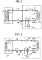
- Fig.3 shows a refrigeration cycle of a third embodiment.
- the reference number 10 represents a compressor, 11 represents a 4-way valve, 12 represents a outdoor heat exchanger, 13 represents a dryer, 14 represents an expansion device, 15 represents an indoor heat exchanger, and 16 represents indoor-outdoor connection pipes.
- the compressor 10, the 4-way valve 11, the outdoor heat exchanger 12, the dryer 13, and the expansion device 14 are built in an outdoor unit.
- the reference number 17 represents a gas sensor, 18 represents a discharge electric valve, 19 represents a fan, 47 represents an indoor fan, and 50 represents an outdoor fan.
- the gas sensor 17 is disposed in an indoor unit, and the discharge electric valve 18 is disposed in a connection portion between the outdoor unit and the indoor-outdoor connection pipe 16.
- the fan 19 is disposed adjacent to the discharge electric valve 18.
- propane is used as a refrigerant
- carbonate compound is charged in the compressor 10 as a refrigerating machine oil.
- the same dryer as in the first embodiment was used.
- the present embodiment has the structure in which the fan 19 is added to the first embodiment, and with this structure, propane discharged from the discharge electric valve 18 to the atmosphere while dispersing the propane by the fan 19. Therefore, the propane can be discharged to the atmosphere more safely. Further, since the indoor fan and the outdoor fan are operated at the same time to disperse the leaked refrigerant, safety is further improved.
- the indoor unit is provided with the gas sensor in the present embodiment
- the present invention is not limited to this. It is also effective to dispose the gas sensor in the outdoor unit.
- the indoor-outdoor connection pipes are pipes built into a building, it is effective for improving safety to dispose the gas sensor in the pipe.
- the gas sensor may not be disposed only in place, and when it seems that a degree of danger is high, a plurality of gas sensors can be disposed.
- the fan used in the present invention various fans such as a sirocco fan and a propeller fan can be used, and the fan may have any type if it has the function to stir the discharged refrigerant with blades.
- Fig.4 shows a refrigeration cycle of a fourth embodiment
- Fig.5 shows a burner portion
- the reference number 20 represents a compressor
- 21 represents a 4-way valve
- 22 represents a outdoor heat exchanger
- 23 represents a dryer
- 24 represents an expansion device
- 25 represents an indoor heat exchanger
- 26 represents indoor-outdoor connection pipes.
- the compressor 20, the 4-way valve 21, the outdoor heat exchanger 22, the dryer 23, and the expansion device 24 are built in an outdoor unit.
- the reference number 27 represents a gas sensor
- 28 represents a discharge electric valve
- 29 represents a burner portion.
- the gas sensor 27 is disposed in an indoor unit
- the discharge electric valve 28 is disposed in a connection portion between the outdoor unit and the indoor-outdoor connection pipe 26.
- the burner portion 29 is disposed adjacent to the discharge electric valve 28.
- propane is used as a refrigerant
- carbonate compound is charged in the compressor 20 as a refrigerating machine oil.
- the same dryer as in the first embodiment was used.
- the present embodiment has the structure in which the burner portion 29 is added in the second embodiment.
- Propane to be discharged from the discharge electric valve 28 to the atmosphere passes through a nozzle 32 from a gas flow passage 31 inside a cylindrical body 30 in the burner portion 29, while the propane mixes with a portion of air sucked and introduced from open air introducing portions 33, and the propane mixed with the air is introduced to a flame port 34 where the propane is ignited by an ignition element 35, and is burnt so that the propane is decomposed into carbon dioxide and water, and discharged to the atmosphere.
- the flame is detected using a flame rod 36 as an attachment. Therefore, the refrigerant can safely be discharged from the air conditioner.
- Bunsen burner In the present embodiment, a generally called Bunsen burner is used, but the present invention is not limited to this.
- the burner may be of a complete previously mixing type, or a dispersion type in which the open air is introduced by a fan.
- a refrigerant which is a fuel is provided for oneself by the internal pressure, it can not be said that the supply state is constant and therefore, it is considered that the Bunsen burner in which a portion of open air is sucked and mixed is most preferable.
- the indoor unit is provided with the gas sensor in the present embodiment
- the present invention is not limited to this. It is also effective to dispose the gas sensor in the outdoor unit.
- the indoor-outdoor connection pipes are pipes built into a building, it is effective for improving safety to dispose the gas sensor in the pipe.
- the gas sensor may not be disposed only in place, and when it seems that a degree of danger is high, a plurality of gas sensors can be disposed.
- a fifth embodiment is characterized in that the burner portion in the fourth embodiment is a catalyst burning type, and other portions are the same as those of the fourth embodiment. Therefore, the burner portion will be explained in detail with reference to Fig.6.
- the burner portion is disposed adjacent to the refrigerant discharge electric valve in a cylindrical body 37, and comprises, therein, a gas flow passage 38, a nozzle 39, open air introducing paths 40, a mesh 41, a catalyst 42, and an ignition element 43.
- a refrigerant to be discharged passes through the refrigerant flow passage 38, and while the refrigerant passes through the nozzle 39, a portion of air from the open air introducing paths 40 is sucked and mixed with the refrigerant, and passes through the mesh 41, and is introduced to the catalyst 42.
- the ignition element 43 is disposed adjacent to the catalyst 42, and when the refrigerant which has passed through the catalyst 42 is ignited, the refrigerant is first fired at the catalyst and then, within few seconds, the catalyst 42 is heated, and the firing position is moved to the catalyst 42 such that the refrigerant is backfired. Thereafter, the refrigerant is stably burnt in a condition of catalyst combustion manner continuously at the catalyst.
- the mesh 41 is used for safety when the supply of the refrigerant which is the fuel is unstable and the refrigerant is further backfired. When the refrigerant is backfired, if the refrigerant is supplied again, since the catalyst 42 itself is has a temperature at which the catalyst 42 is sufficiently activated, the catalyst combustion at the catalyst 42 can be continued without again igniting by the ignition element.
- the fire does not go out by wind from outside, and even when the supply speed of the refrigerant which is the fuel is unstable, and after fire goes out unlike the flame combustion, it is possible to catch fire to continue the combustion again. Therefore, it is possible to stably and completely burn out the refrigerant to the end.
- the burner portion can be formed compactly.
- the compressor in which the refrigerating machine oil having less mutual solubility with the refrigerant is used.
- the refrigerating machine oil having less mutual solubility with the refrigerant since the refrigerant is not dissolved in the refrigerating machine oil almost at all, it is easy to draw out the refrigerant in the refrigeration cycle and to discharge the refrigerant to the atmosphere, and it is possible to prevent the permanent leakage from the leaking position.
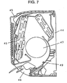
- Fig.7 is a sectional side view of an indoor unit.
- a heat exchanger 46 and a cross flow fan 47 are disposed in a frame 44 and a front surface grille 45.
- a ventilation circuit in the indoor unit is formed such that the air sucked by the front surface grille 45 passes through the heat exchanger 46 so that the air is heated or cooled and then, the air is further blown by the cross flow fan 47, and the warm or cool wind is blown into an indoor space from a transfer grille 48.
- the gas sensor 49 is fixed, e.g., on the frame 44 between the cross flow fan 47 and the transfer grille 48 in the ventilation circuit.
- the refrigerant in the refrigeration cycle leaks from the indoor unit into an indoor space
- the ventilation circuit is provided in the indoor unit
- the refrigerant leaks from a copper pipe of the heat exchanger 46. Since the refrigerant is greater in density than air, it is considered that the refrigerant is dispersed downward and is discharged from the transfer grille 48 into the indoor space in many cases.
- the air conditioner since the cross flow fan 47 is rotating of course, the refrigerant is discharged from the transfer grille 48. Therefore, by fixing and disposing the gas sensor 49 on the frame 44 between the cross flow fan 47 and the transfer grille 48, it is possible to detect most refrigerant leaking in the indoor unit.
- carbonate compound (ratio of 28% carbon forming carbonic acid ester bond) shown in the chemical formula 1 is used as the refrigerating machine oil.
- the ratio of carbon forming carbonic acid ester bond is 10 atomic % or higher with respect to all the number of carbon forming the carbonate compound.
- the ratio exceeds 30 atomic %, since the thermal stability as the refrigerating machine oil is largely deteriorated, it is considered that the optimal range of the ratio is 10 to 30 atomic %.
- the refrigerant when a flammable refrigerant leaks, the refrigerant is discharged out to a safe place, i.e., to the atmosphere. Therefore, it is possible to prevent the refrigerant from being accumulated in a dangerous place.
Description

Claims (12)
- An air conditioner, in which a refrigeration cycle comprises an indoor unit and an outdoor unit formed integrally to the air conditioner, an indoor heat exchanger (6) included in said indoor unit, an outdoor heat exchanger .(3) included in said outdoor unit, a compressor (1), and an expansion device (5) which are annularly connected to one another through pipes (7), said refrigeration cycle uses a flammable refrigerant as a refrigerant, and said indoor unit and said outdoor unit are connected with each other using connection pipes (7),
characterised in that
said refrigeration cycle is provided with a gas sensor (8) and a refrigerant discharge portion (9), said gas sensor (8) monitors leakage of said refrigerant from said refrigeration cycle toward outside, after the leakage is detected by said gas sensor (8), said discharge portion (9) is opened to discharge said refrigerant outside. - An air conditioner according to claim 1, wherein said indoor unit is provided with said gas sensor (8), and said outdoor unit or the connection pipes (7) are provided with said refrigerant discharge portion (9).
- An air conditioner according to claim 1, further comprising a fan (19) disposed in said refrigeration cycle rotating while said refrigerant discharge portion (18) is opened to discharge said refrigerant outside.
- An air conditioner according to claim 3, wherein said indoor unit is provided with said gas sensor (17), and said outdoor unit or the connection pipes are provided with said refrigerant discharge portion (18) and said fan (19).
- An air conditioner according to claim 1, further comprising a burner portion (29) disposed in said refrigeration cycle burning said refrigerant while the discharge portion (28) is opened to discharge said refrigerant outside.
- An air conditioner according to claim 5, wherein said indoor unit is provided with said gas sensor (27), and said outdoor unit or the connection pipes (26) are provided with said air refrigeration discharge portion (28) and said burner portion (29).
- An air conditioner according to claim 6, wherein said flammable refrigerant in said refrigeration cycle and a portion of outside air are previously mixed by a burner portion (29).
- An air conditioner according to claim 6, wherein said flammable refrigerant is burnt by said burner portion (29) in a catalyst combustion manner.
- An air conditioner according to any one of claims 1 to 6, wherein said flammable refrigerant comprising, as main component, one of propane, isobutane and ethane, or a mixture of a plurality of these components.
- An air conditioner according to any one of claims 1 to 6, wherein a refrigeration machine oil in said compressor (1, 10, 20) has less mutual solubility with said flammable refrigerant.
- An air conditioner according to any one of claims 1 to 6, wherein said compressor (1, 10, 20) is an oil-free compressor into which a refrigerating machine oil is not charged.
- An air conditioner according to any one of claims 1 to 6, wherein said gas sensor (8, 17, 27) is disposed between a ventilation fan (47) and a transfer grille (48) in an indoor unit ventilation circuit.
Applications Claiming Priority (2)
| Application Number | Priority Date | Filing Date | Title |
|---|---|---|---|
| JP11315098A JP3775920B2 (en) | 1998-04-23 | 1998-04-23 | Air conditioner |
| JP11315098 | 1999-11-05 |
Publications (3)
| Publication Number | Publication Date |
|---|---|
| EP0952408A2 EP0952408A2 (en) | 1999-10-27 |
| EP0952408A3 EP0952408A3 (en) | 2002-09-11 |
| EP0952408B1 true EP0952408B1 (en) | 2005-07-27 |
Family
ID=14604845
Family Applications (1)
| Application Number | Title | Priority Date | Filing Date |
|---|---|---|---|
| EP99106829A Expired - Lifetime EP0952408B1 (en) | 1998-04-23 | 1999-04-06 | Air conditioner |
Country Status (5)
| Country | Link |
|---|---|
| US (1) | US6085531A (en) |
| EP (1) | EP0952408B1 (en) |
| JP (1) | JP3775920B2 (en) |
| DE (1) | DE69926291T2 (en) |
| ES (1) | ES2245057T3 (en) |
Cited By (1)
| Publication number | Priority date | Publication date | Assignee | Title |
|---|---|---|---|---|
| CN104101128A (en) * | 2014-07-09 | 2014-10-15 | 华中科技大学 | Refrigerating system adapting to flammable refrigerant and control method of refrigerating system |
Families Citing this family (50)
| Publication number | Priority date | Publication date | Assignee | Title |
|---|---|---|---|---|
| US6209338B1 (en) * | 1998-07-15 | 2001-04-03 | William Bradford Thatcher, Jr. | Systems and methods for controlling refrigerant charge |
| JP3159200B2 (en) * | 1999-03-02 | 2001-04-23 | ダイキン工業株式会社 | Air conditioner |
| KR100379283B1 (en) * | 1999-09-21 | 2003-04-08 | 만도공조 주식회사 | Automatic Leakage Checking Method Of Sperating Type Air-Conditioner |
| AU777879B2 (en) * | 2000-09-26 | 2004-11-04 | Daikin Industries, Ltd. | Air conditioner |
| JP4599699B2 (en) * | 2000-09-26 | 2010-12-15 | ダイキン工業株式会社 | Air conditioner |
| US6601773B2 (en) * | 2001-02-21 | 2003-08-05 | Sanyo Electric Co., Ltd. | Heat pump type hot water supply apparatus |
| JP4042487B2 (en) * | 2001-09-27 | 2008-02-06 | 株式会社デンソー | Air conditioner for vehicles |
| US6907748B2 (en) * | 2003-02-28 | 2005-06-21 | Delphi Technologies, Inc. | HVAC system with refrigerant venting |
| DE10318504B3 (en) * | 2003-04-24 | 2004-11-18 | Robert Bosch Gmbh | Monitoring leakage from vehicle air conditioners employing carbon dioxide working fluid, warns driver of rising concentration in passenger compartment and initiates safety precautions |
| DE10320021B4 (en) * | 2003-05-06 | 2005-06-23 | Danfoss Compressors Gmbh | Refrigerant compressor arrangement |
| US6912860B2 (en) * | 2003-08-08 | 2005-07-05 | Delphi Technologies, Inc. | Method of operating a directed relief valve in an air conditioning system |
| JP4255807B2 (en) | 2003-11-06 | 2009-04-15 | 株式会社不二工機 | Expansion valve with electromagnetic relief valve |
| JP2005241121A (en) * | 2004-02-26 | 2005-09-08 | Mitsubishi Heavy Ind Ltd | Air conditioner |
| JP4243211B2 (en) * | 2004-04-06 | 2009-03-25 | 株式会社テージーケー | Refrigeration system |
| TWI273492B (en) * | 2004-05-18 | 2007-02-11 | Cyberlink Corp | Encryption/decryption method incorporated with local server software |
| US20060101844A1 (en) * | 2004-11-12 | 2006-05-18 | Manole Dan M | Hydrocarbon refrigeration system with convection channel |
| US7107786B2 (en) * | 2004-11-12 | 2006-09-19 | Tecumseh Products Company | Apparatus for and method of venting hydrocarbon refrigerant leaks |
| CN100560847C (en) * | 2004-12-06 | 2009-11-18 | Lg电子株式会社 | Dryer |
| ITTO20050839A1 (en) * | 2005-11-28 | 2007-05-29 | Faiveley Transp Piossasco S P A | GROUP OF GENERATION AND TREATMENT OF FLUIDS COMPRESSED AERIFORMS, WITH IMPROVED COOLING SYSTEM. |
| AT503293B1 (en) * | 2006-05-05 | 2007-09-15 | Fronius Int Gmbh | Cooling system for fuel cell, has pump for delivering coolant and provision is made for de-ionizing resin to arrange in container in interior of equalization container |
| US7814757B2 (en) * | 2006-09-12 | 2010-10-19 | Delphi Technologies, Inc. | Operating algorithm for refrigerant safety system |
| US7677049B2 (en) * | 2007-02-28 | 2010-03-16 | Delphi Technologies, Inc. | Algorithm for activation of directed relief system from vehicle accelerometers during crash |
| DE102009005923A1 (en) * | 2009-01-23 | 2010-07-29 | Linde Aktiengesellschaft | Method and device for discharging leakage gas from an evaporator |
| JP2012013348A (en) * | 2010-07-02 | 2012-01-19 | Panasonic Corp | Air conditioner |
| CN202392894U (en) * | 2011-11-15 | 2012-08-22 | 开利公司 | Air-conditioner terminal device, air-conditioner and data center |
| CN103322641B (en) * | 2012-03-21 | 2016-06-01 | 广东美芝精密制造有限公司 | Use the method for controlling security of flammable coolant air-conditioner |
| JP5673612B2 (en) * | 2012-06-27 | 2015-02-18 | 三菱電機株式会社 | Refrigeration cycle equipment |
| AU2013101100B4 (en) * | 2013-08-17 | 2013-11-07 | Pioneer International Pty Ltd | An Arrangement and Method For Retrofitting an Air Conditioning System |
| JP5812081B2 (en) | 2013-11-12 | 2015-11-11 | ダイキン工業株式会社 | Indoor unit |
| US9528726B2 (en) * | 2014-03-14 | 2016-12-27 | Hussmann Corporation | Low charge hydrocarbon refrigeration system |
| US9746209B2 (en) * | 2014-03-14 | 2017-08-29 | Hussman Corporation | Modular low charge hydrocarbon refrigeration system and method of operation |
| US9302565B2 (en) | 2014-06-09 | 2016-04-05 | Ford Global Technologies, Llc | Circulation for pressure loss event |
| JP6248898B2 (en) * | 2014-10-31 | 2017-12-20 | ダイキン工業株式会社 | Air conditioner |
| JP5983707B2 (en) * | 2014-10-31 | 2016-09-06 | ダイキン工業株式会社 | Air conditioner indoor unit |
| CN104501302B (en) * | 2014-11-21 | 2017-09-26 | 华中科技大学 | A kind of cabinet air conditioner and its control method |
| JP6223324B2 (en) * | 2014-12-17 | 2017-11-01 | 三菱電機株式会社 | Refrigerant leak detection device and refrigeration cycle device |
| WO2016151642A1 (en) * | 2015-03-26 | 2016-09-29 | 三菱電機株式会社 | Indoor unit for air conditioner |
| JP6479569B2 (en) * | 2015-05-15 | 2019-03-06 | 三菱重工サーマルシステムズ株式会社 | Air conditioner and control method of air conditioner |
| JP6213534B2 (en) * | 2015-08-13 | 2017-10-18 | 三菱電機株式会社 | Air conditioner |
| US10151663B2 (en) * | 2015-09-15 | 2018-12-11 | Emerson Climate Technologies, Inc. | Leak detector sensor systems using tag-sensitized refrigerants |
| WO2017083333A1 (en) | 2015-11-09 | 2017-05-18 | Carrier Corporation | Parallel loop intermodal container |
| US10670322B2 (en) | 2015-11-09 | 2020-06-02 | Carrier Corporation | Series loop intermodal container |
| WO2017109847A1 (en) * | 2015-12-22 | 2017-06-29 | 三菱電機株式会社 | Air conditioner |
| CN105890116B (en) * | 2016-04-27 | 2019-02-15 | 芜湖美智空调设备有限公司 | The detection method and system of air conditioner coolant leakage |
| JP6545373B2 (en) * | 2016-05-17 | 2019-07-17 | 三菱電機株式会社 | Air conditioner |
| US11274861B2 (en) | 2016-10-10 | 2022-03-15 | Johnson Controls Technology Company | Method and apparatus for isolating heat exchanger from the air handling unit in a single-packace outdoor unit |
| US11199337B2 (en) * | 2018-04-09 | 2021-12-14 | Mitsubishi Electric Corporation | Air conditioner |
| WO2020055685A1 (en) * | 2018-09-10 | 2020-03-19 | Carrier Corporation | Gas monitoring apparatus and method |
| US11435101B2 (en) * | 2019-09-26 | 2022-09-06 | Rheem Manufacturing Company | Air mover refrigerant leak detection and risk mitigation |
| US20210222923A1 (en) * | 2020-06-11 | 2021-07-22 | Beijing Baidu Netcom Science And Technology Co., Ltd. | Refrigerating system |
Family Cites Families (9)
| Publication number | Priority date | Publication date | Assignee | Title |
|---|---|---|---|---|
| US4711096A (en) * | 1986-03-17 | 1987-12-08 | Krantz Herman F | Leak detection and refrigerant purging system |
| JPH0755267A (en) | 1993-08-20 | 1995-03-03 | Matsushita Electric Ind Co Ltd | Air conditioner |
| JP2990570B2 (en) | 1994-08-18 | 1999-12-13 | 松下電器産業株式会社 | Integrated air conditioner |
| US5551247A (en) * | 1994-09-30 | 1996-09-03 | Spx Corporation | Refrigerant handling system and method especially for flammable and potentially flammable refrigerants |
| JP3523381B2 (en) * | 1995-07-26 | 2004-04-26 | 株式会社日立製作所 | refrigerator |
| JPH0959609A (en) | 1995-08-18 | 1997-03-04 | Matsushita Electric Ind Co Ltd | Mixed working fluid containing trifluoroiodomethane and refrigeration cycle equipment |
| JP3339268B2 (en) * | 1995-09-12 | 2002-10-28 | 株式会社デンソー | Vehicle air conditioner |
| US5918475A (en) * | 1995-10-11 | 1999-07-06 | Denso Corporation | Air conditioning apparatus for vehicle, using a flammable refrigerant |
| JPH09324928A (en) * | 1996-06-05 | 1997-12-16 | Daikin Ind Ltd | Air conditioner using combustible refrigerant |
-
1998
- 1998-04-23 JP JP11315098A patent/JP3775920B2/en not_active Expired - Fee Related
-
1999
- 1999-03-30 US US09/280,688 patent/US6085531A/en not_active Expired - Lifetime
- 1999-04-06 DE DE69926291T patent/DE69926291T2/en not_active Expired - Lifetime
- 1999-04-06 EP EP99106829A patent/EP0952408B1/en not_active Expired - Lifetime
- 1999-04-06 ES ES99106829T patent/ES2245057T3/en not_active Expired - Lifetime
Cited By (2)
| Publication number | Priority date | Publication date | Assignee | Title |
|---|---|---|---|---|
| CN104101128A (en) * | 2014-07-09 | 2014-10-15 | 华中科技大学 | Refrigerating system adapting to flammable refrigerant and control method of refrigerating system |
| CN104101128B (en) * | 2014-07-09 | 2017-01-25 | 华中科技大学 | Refrigerating system adapting to flammable refrigerant and control method of refrigerating system |
Also Published As
| Publication number | Publication date |
|---|---|
| US6085531A (en) | 2000-07-11 |
| JP3775920B2 (en) | 2006-05-17 |
| DE69926291D1 (en) | 2005-09-01 |
| JPH11304226A (en) | 1999-11-05 |
| EP0952408A2 (en) | 1999-10-27 |
| ES2245057T3 (en) | 2005-12-16 |
| EP0952408A3 (en) | 2002-09-11 |
| DE69926291T2 (en) | 2006-01-12 |
Similar Documents
| Publication | Publication Date | Title |
|---|---|---|
| EP0952408B1 (en) | Air conditioner | |
| CN103673095B (en) | Refrigeration cycle device | |
| JP3159200B2 (en) | Air conditioner | |
| JP6556385B1 (en) | Air conditioner | |
| JP5136790B2 (en) | Fire extinguisher | |
| JP2004012127A (en) | Refrigerator using inflammable refrigerant | |
| AU2010364872B2 (en) | Part replacement method for refrigeration cycle device | |
| JP2004069295A (en) | Refrigerator using inflammable refrigerant | |
| JP2005009857A (en) | Freezing device and refrigerant leakage detection method | |
| JPH11125482A (en) | Ant-explosion unit for refrigerating machine employing inflammable coolant | |
| JPH09264641A (en) | Refrigerating cycle device | |
| JP2007139375A (en) | Method and device for preventing fire and for extinguishing fire for refrigerating cycle that uses inflammable coolant gas | |
| JP2000028237A (en) | Separation type refrigerating cycle apparatus | |
| JPH1035266A (en) | Automobile air conditioner | |
| EP0726430B1 (en) | Air conditioning apparatus and method having a refrigerating fluid which is not harmful to at least the ozone layer | |
| JP3245475U (en) | room air conditioner | |
| JP4476522B2 (en) | Evaporator with defrost heater and refrigerator using the evaporator | |
| JP4178649B2 (en) | Air conditioner | |
| JP2003287343A (en) | Cooling storage | |
| KR102661388B1 (en) | Windless chamber for battery testing | |
| JP2000234797A (en) | Indoor unit of refrigeration cycle device, and its installation method | |
| JP2000097505A (en) | Air conditioner | |
| JP2000251137A (en) | Cooling system for automatic vending machine | |
| JPH08303882A (en) | Method of operating heat pump using new alternative refrigerant gas hfc | |
| JP2000146429A (en) | Freezing device |
Legal Events
| Date | Code | Title | Description |
|---|---|---|---|
| PUAI | Public reference made under article 153(3) epc to a published international application that has entered the european phase |
Free format text: ORIGINAL CODE: 0009012 |
|
| AK | Designated contracting states |
Kind code of ref document: A2 Designated state(s): AT BE CH CY DE DK ES FI FR GB GR IE IT LI LU MC NL PT SE |
|
| AX | Request for extension of the european patent |
Free format text: AL;LT;LV;MK;RO;SI |
|
| PUAL | Search report despatched |
Free format text: ORIGINAL CODE: 0009013 |
|
| AK | Designated contracting states |
Kind code of ref document: A3 Designated state(s): AT BE CH CY DE DK ES FI FR GB GR IE IT LI LU MC NL PT SE |
|
| AX | Request for extension of the european patent |
Free format text: AL;LT;LV;MK;RO;SI |
|
| RIC1 | Information provided on ipc code assigned before grant |
Free format text: 7F 24F 11/00 A, 7F 25B 49/00 B |
|
| 17P | Request for examination filed |
Effective date: 20021009 |
|
| AKX | Designation fees paid |
Designated state(s): DE ES GR IT SE |
|
| 17Q | First examination report despatched |
Effective date: 20040405 |
|
| GRAP | Despatch of communication of intention to grant a patent |
Free format text: ORIGINAL CODE: EPIDOSNIGR1 |
|
| GRAS | Grant fee paid |
Free format text: ORIGINAL CODE: EPIDOSNIGR3 |
|
| GRAA | (expected) grant |
Free format text: ORIGINAL CODE: 0009210 |
|
| AK | Designated contracting states |
Kind code of ref document: B1 Designated state(s): DE ES GR IT SE |
|
| REF | Corresponds to: |
Ref document number: 69926291 Country of ref document: DE Date of ref document: 20050901 Kind code of ref document: P |
|
| REG | Reference to a national code |
Ref country code: SE Ref legal event code: TRGR |
|
| REG | Reference to a national code |
Ref country code: GR Ref legal event code: EP Ref document number: 20050403026 Country of ref document: GR |
|
| REG | Reference to a national code |
Ref country code: ES Ref legal event code: FG2A Ref document number: 2245057 Country of ref document: ES Kind code of ref document: T3 |
|
| PLBE | No opposition filed within time limit |
Free format text: ORIGINAL CODE: 0009261 |
|
| STAA | Information on the status of an ep patent application or granted ep patent |
Free format text: STATUS: NO OPPOSITION FILED WITHIN TIME LIMIT |
|
| 26N | No opposition filed |
Effective date: 20060428 |
|
| REG | Reference to a national code |
Ref country code: ES Ref legal event code: PC2A |
|
| PGFP | Annual fee paid to national office [announced via postgrant information from national office to epo] |
Ref country code: ES Payment date: 20100423 Year of fee payment: 12 |
|
| PGFP | Annual fee paid to national office [announced via postgrant information from national office to epo] |
Ref country code: IT Payment date: 20100417 Year of fee payment: 12 Ref country code: DE Payment date: 20100430 Year of fee payment: 12 |
|
| PGFP | Annual fee paid to national office [announced via postgrant information from national office to epo] |
Ref country code: SE Payment date: 20100409 Year of fee payment: 12 |
|
| PGFP | Annual fee paid to national office [announced via postgrant information from national office to epo] |
Ref country code: GR Payment date: 20100322 Year of fee payment: 12 |
|
| REG | Reference to a national code |
Ref country code: DE Ref legal event code: R119 Ref document number: 69926291 Country of ref document: DE |
|
| REG | Reference to a national code |
Ref country code: DE Ref legal event code: R119 Ref document number: 69926291 Country of ref document: DE |
|
| REG | Reference to a national code |
Ref country code: SE Ref legal event code: EUG |
|
| REG | Reference to a national code |
Ref country code: GR Ref legal event code: ML Ref document number: 20050403026 Country of ref document: GR Effective date: 20111102 |
|
| PG25 | Lapsed in a contracting state [announced via postgrant information from national office to epo] |
Ref country code: IT Free format text: LAPSE BECAUSE OF NON-PAYMENT OF DUE FEES Effective date: 20110406 Ref country code: GR Free format text: LAPSE BECAUSE OF NON-PAYMENT OF DUE FEES Effective date: 20111102 |
|
| PG25 | Lapsed in a contracting state [announced via postgrant information from national office to epo] |
Ref country code: SE Free format text: LAPSE BECAUSE OF NON-PAYMENT OF DUE FEES Effective date: 20110407 |
|
| REG | Reference to a national code |
Ref country code: ES Ref legal event code: FD2A Effective date: 20130606 |
|
| PG25 | Lapsed in a contracting state [announced via postgrant information from national office to epo] |
Ref country code: DE Free format text: LAPSE BECAUSE OF NON-PAYMENT OF DUE FEES Effective date: 20111031 |
|
| PG25 | Lapsed in a contracting state [announced via postgrant information from national office to epo] |
Ref country code: ES Free format text: LAPSE BECAUSE OF NON-PAYMENT OF DUE FEES Effective date: 20110407 |