EP0952367A2 - Hydraulic system for a power-take-off clutch - Google Patents
Hydraulic system for a power-take-off clutch Download PDFInfo
- Publication number
- EP0952367A2 EP0952367A2 EP99107725A EP99107725A EP0952367A2 EP 0952367 A2 EP0952367 A2 EP 0952367A2 EP 99107725 A EP99107725 A EP 99107725A EP 99107725 A EP99107725 A EP 99107725A EP 0952367 A2 EP0952367 A2 EP 0952367A2
- Authority
- EP
- European Patent Office
- Prior art keywords
- clutch
- pressure
- power
- brake
- take
- Prior art date
- Legal status (The legal status is an assumption and is not a legal conclusion. Google has not performed a legal analysis and makes no representation as to the accuracy of the status listed.)
- Granted
Links
- 239000012530 fluid Substances 0.000 claims abstract description 6
- 230000001050 lubricating effect Effects 0.000 claims abstract description 5
- 230000005540 biological transmission Effects 0.000 description 1
- 238000010276 construction Methods 0.000 description 1
- 238000010586 diagram Methods 0.000 description 1
- 239000010687 lubricating oil Substances 0.000 description 1
- 239000003921 oil Substances 0.000 description 1
Images
Classifications
-
- B—PERFORMING OPERATIONS; TRANSPORTING
- B60—VEHICLES IN GENERAL
- B60K—ARRANGEMENT OR MOUNTING OF PROPULSION UNITS OR OF TRANSMISSIONS IN VEHICLES; ARRANGEMENT OR MOUNTING OF PLURAL DIVERSE PRIME-MOVERS IN VEHICLES; AUXILIARY DRIVES FOR VEHICLES; INSTRUMENTATION OR DASHBOARDS FOR VEHICLES; ARRANGEMENTS IN CONNECTION WITH COOLING, AIR INTAKE, GAS EXHAUST OR FUEL SUPPLY OF PROPULSION UNITS IN VEHICLES
- B60K17/00—Arrangement or mounting of transmissions in vehicles
- B60K17/28—Arrangement or mounting of transmissions in vehicles characterised by arrangement, location, or type of power take-off
-
- B—PERFORMING OPERATIONS; TRANSPORTING
- B60—VEHICLES IN GENERAL
- B60K—ARRANGEMENT OR MOUNTING OF PROPULSION UNITS OR OF TRANSMISSIONS IN VEHICLES; ARRANGEMENT OR MOUNTING OF PLURAL DIVERSE PRIME-MOVERS IN VEHICLES; AUXILIARY DRIVES FOR VEHICLES; INSTRUMENTATION OR DASHBOARDS FOR VEHICLES; ARRANGEMENTS IN CONNECTION WITH COOLING, AIR INTAKE, GAS EXHAUST OR FUEL SUPPLY OF PROPULSION UNITS IN VEHICLES
- B60K25/00—Auxiliary drives
- B60K25/02—Auxiliary drives directly from an engine shaft
- B60K2025/026—Auxiliary drives directly from an engine shaft by a hydraulic transmission
Definitions
- the invention relates to a hydraulic system for a power-take-off clutch in a utility vehicle such as an agricultural tractor.
- power-take-offs in utility vehicles such as agricultural tractors, for example, are engaged for only some of the time that the vehicle is used.
- the clutch When engaged, the clutch has to transmit in large torque to the power-take-off to drive an implement of some sort.
- substantial quantities of oil have to be delivered to the lubricating circuit in order to lubricate and cool the power-take-off clutch and gearbox.
- the power-take-off hydraulic system is designed to operate at a relatively high system pressure.
- the power-take-off clutch is released, only the power-take-off brake, which is subject to minimal loading, is engaged and only the part of the released clutch on the drive side is supplied with lubricating oil.
- a significantly lower system pressure would be sufficient for this purpose. Since the power requirement of the pump depends on the system pressure, the pump will undergo a considerable loss of power if the system pressure remains constant, which in turn causes the hydraulic medium to heat up considerably.
- a hydraulic system has already been disclosed which provides a means of keeping the loss of power in the pump as low as possible, in which a high system pressure is applied to the power-take-off (PTO) clutch and a comparatively reduced system pressure is applied to the PTO brake.
- the known hydraulic system contains a control valve for selecting the clutch or the brake and two pressure-limiting valves, the first of these pressure-limiting valves limiting the pump pressure to the high system pressure as soon as the clutch is selected via the control valve and the second pressure-limiting valve limiting the pump pressure to the lower system pressure when the brake is engaged as soon as the brake is selected via the control valve. Hydraulic fluid flowing off through the pressure-limiting valves is fed into the lubricating circuit via respective check-valves.
- the disadvantage of the known system is the relatively high number of components it requires.
- the control valve a 4/2 way valve, is restricted to use on hydraulic systems for PTOs with alternately selected clutch and brake.
- the objective of the invention is to reduce the construction requirements for a hydraulic system of the type described above.
- the objective is achieved by the invention due to the fact that the system pressures are controlled directly by the pressure applied to the engaged clutch. This means that the system pressures can be adjusted irrespective of the design of the control valve used. Consequently, less expensive 3/2-way valves or 3/2-control valves can be used as the control valve. Furthermore, only one, adjustable, limiting valve is required.
- the feature whereby the closing force of the pressure-limiting valve depends on the pressure applied to the clutch has an advantage in that different system pressure can be generated with single, adjustable, pressure-limiting valve only.
- a fully self-sufficient PTO at the front end of an agricultural tractor has a multiple-disc clutch 1 which is engaged by hydraulic pressure, and a brake 2.
- Clutch 1 and brake 2 can be alternately mechanically operated, which means that when the clutch 1 is engaged, the brake 2 is necessarily mechanically released and when the clutch 1 is released, the brake 2 is engaged by a spring-operated mechanism.
- the structural design of this clutch/brake system is described in detail in co-pending patent application number [ ].
- the brake is only actuated hydraulically to the extent that when there is pressure in the hydraulic system at all, a hydraulically actuated brake “back stop” moves into an “active” position in which disengagement of the clutch automatically results in engagement of the brake. When there is no system pressure, the brake is “disabled” by this "back stop” moving away from the “active” position.
- the half of the clutch 1a at the drive end is driven by the engine 3 of the tractor.
- a shaft 4 extending from the half of the clutch 1b at the output end bears a friction disc 2a of the brake 2 and a set 5 of different gears forming a number of transmission ratios in conjunction with gears of another set 6, by means of which a specific speed can be set on the PTO shaft 7.
- Hydraulic fluid is delivered to the clutch 1 and the brake 2 by means of a hydraulic system, which is supplied by a pump 8 driven by the engine 3.
- the pump 8 delivers hydraulic fluid at a maximum pressure of 25 bar, predetermined by a pressure-limiting valve 9, to a line 10, which is shut off in terms of pressure by means of another pressure-limiting valve 12 lying on a line 11 branching off therefrom.
- the line 11 runs from the pressure-limiting valve 12 into a lubricating circuit.
- the pressure-limiting valve 12 limits the pressure to a system pressure of either 18 bar or 4 bar in the line 10 leading to a control valve 13 and in line 14 leading to the brake 2.
- the control valve 13 can be infinitely adjusted between a first control position in which the line 17 to the clutch is vented and without pressure and a second control position in which the line 17 is connected to the line 10 and freely transmits the system pressure prevailing in line 10.
- the piston 16 and the clutch 1 are not pressurised because there is no pressure in line 17.
- the closing spring 15 of the pressure-limiting valve 12 is pre-loaded in such a way that when no pressure is being applied to the piston 16 in line 17 a low system pressure of 4 bar is generated. This pressure keeps the brake 2 in the "active" position by pressurising it.
Landscapes
- Engineering & Computer Science (AREA)
- Chemical & Material Sciences (AREA)
- Combustion & Propulsion (AREA)
- Transportation (AREA)
- Mechanical Engineering (AREA)
- Hydraulic Clutches, Magnetic Clutches, Fluid Clutches, And Fluid Joints (AREA)
- Auxiliary Drives, Propulsion Controls, And Safety Devices (AREA)
- Arrangement And Driving Of Transmission Devices (AREA)
Abstract
Description
- The invention relates to a hydraulic system for a power-take-off clutch in a utility vehicle such as an agricultural tractor.
- As a rule, power-take-offs in utility vehicles such as agricultural tractors, for example, are engaged for only some of the time that the vehicle is used. When engaged, the clutch has to transmit in large torque to the power-take-off to drive an implement of some sort. Furthermore, substantial quantities of oil have to be delivered to the lubricating circuit in order to lubricate and cool the power-take-off clutch and gearbox. For this reason, the power-take-off hydraulic system is designed to operate at a relatively high system pressure. When the power-take-off clutch is released, only the power-take-off brake, which is subject to minimal loading, is engaged and only the part of the released clutch on the drive side is supplied with lubricating oil. A significantly lower system pressure would be sufficient for this purpose. Since the power requirement of the pump depends on the system pressure, the pump will undergo a considerable loss of power if the system pressure remains constant, which in turn causes the hydraulic medium to heat up considerably.
- A hydraulic system has already been disclosed which provides a means of keeping the loss of power in the pump as low as possible, in which a high system pressure is applied to the power-take-off (PTO) clutch and a comparatively reduced system pressure is applied to the PTO brake. The known hydraulic system contains a control valve for selecting the clutch or the brake and two pressure-limiting valves, the first of these pressure-limiting valves limiting the pump pressure to the high system pressure as soon as the clutch is selected via the control valve and the second pressure-limiting valve limiting the pump pressure to the lower system pressure when the brake is engaged as soon as the brake is selected via the control valve. Hydraulic fluid flowing off through the pressure-limiting valves is fed into the lubricating circuit via respective check-valves. The disadvantage of the known system is the relatively high number of components it requires. In addition, the control valve, a 4/2 way valve, is restricted to use on hydraulic systems for PTOs with alternately selected clutch and brake.
- The objective of the invention is to reduce the construction requirements for a hydraulic system of the type described above.
- According to the invention, a system is provided having the features of
Claim 1 hereto. - The objective is achieved by the invention due to the fact that the system pressures are controlled directly by the pressure applied to the engaged clutch. This means that the system pressures can be adjusted irrespective of the design of the control valve used. Consequently, less expensive 3/2-way valves or 3/2-control valves can be used as the control valve. Furthermore, only one, adjustable, limiting valve is required.
- The feature whereby the closing force of the pressure-limiting valve depends on the pressure applied to the clutch has an advantage in that different system pressure can be generated with single, adjustable, pressure-limiting valve only.
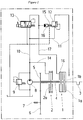
- An embodiment of the invention be described in more detail below, by way of example only, with reference to a drawing, which is a diagram of a hydraulic system according to the invention.
- A fully self-sufficient PTO at the front end of an agricultural tractor has a multiple-
disc clutch 1 which is engaged by hydraulic pressure, and abrake 2.Clutch 1 andbrake 2 can be alternately mechanically operated, which means that when theclutch 1 is engaged, thebrake 2 is necessarily mechanically released and when theclutch 1 is released, thebrake 2 is engaged by a spring-operated mechanism. The structural design of this clutch/brake system is described in detail in co-pending patent application number [ ]. - It should be noted that the brake is only actuated hydraulically to the extent that when there is pressure in the hydraulic system at all, a hydraulically actuated brake "back stop" moves into an "active" position in which disengagement of the clutch automatically results in engagement of the brake. When there is no system pressure, the brake is "disabled" by this "back stop" moving away from the "active" position.
- The half of the
clutch 1a at the drive end is driven by theengine 3 of the tractor. Ashaft 4 extending from the half of theclutch 1b at the output end bears afriction disc 2a of thebrake 2 and aset 5 of different gears forming a number of transmission ratios in conjunction with gears of anotherset 6, by means of which a specific speed can be set on thePTO shaft 7. - Hydraulic fluid is delivered to the
clutch 1 and thebrake 2 by means of a hydraulic system, which is supplied by a pump 8 driven by theengine 3. The pump 8 delivers hydraulic fluid at a maximum pressure of 25 bar, predetermined by a pressure-limitingvalve 9, to aline 10, which is shut off in terms of pressure by means of another pressure-limitingvalve 12 lying on aline 11 branching off therefrom. At the output end, theline 11 runs from the pressure-limitingvalve 12 into a lubricating circuit. The pressure-limitingvalve 12 limits the pressure to a system pressure of either 18 bar or 4 bar in theline 10 leading to acontrol valve 13 and inline 14 leading to thebrake 2. Which of the system pressure actually prevails will depend on the level of the closing force of the pressure-limitingvalve 12, which can be adjusted by the variable initial tension of aclosing spring 15. The initial tension of theclosing spring 15 can in turn be adjusted by applying to apiston 16 the pressure prevailing in aline 17 running from thecontrol valve 12 to theclutch 1. Theline 17 feeds a hydraulic clutch actuator (not shown). - The
control valve 13 can be infinitely adjusted between a first control position in which theline 17 to the clutch is vented and without pressure and a second control position in which theline 17 is connected to theline 10 and freely transmits the system pressure prevailing inline 10. In the first of the above-mentioned control positions, thepiston 16 and theclutch 1 are not pressurised because there is no pressure inline 17. Theclosing spring 15 of the pressure-limitingvalve 12 is pre-loaded in such a way that when no pressure is being applied to thepiston 16 in line 17 a low system pressure of 4 bar is generated. This pressure keeps thebrake 2 in the "active" position by pressurising it. - When switched into the second of the above-mentioned control positions, increasing pressure is applied to
line 17 and hence theclutch 1 and thepiston 16. Starting from the current level of 4 bar system pressure inline 10, the pressure applied to theclutch 1 and thepiston 16 inline 17 is increased, so that thepiston 16 is pushed increasingly in the direction in which it will apply a greater tension to theclosing spring 15 until it finally rests against a stop, not illustrated. In this situation, the closing force of the pressure-limitingvalve 12 reaches a maximum value, corresponding to a system pressure of 18 bar inline 10. With this pressure, theclutch 1 is finally full engaged. The brake "back stop" will remain in the "active" position, but the movement of the clutch into engagement as discussed above, necessarily disengages the brake. - When the
control valve 13 is switched from the first of the above-mentioned control positions (clutch OUT) into the second (clutch IN), there will be controlled rise inpressure line 17 so that an implement driven by thePTO shaft 7 will reach a desired speed after approximately 2-3 seconds. Consequently, thePTO shaft 7 can be engaged under load smoothly and without damage to the PTO.
Claims (1)
- A hydraulic system for a power-take-off clutch in a utility vehicle, such as an agricultural tractor, the system comprising a pump (8) for delivering hydraulic fluid to the clutch (1), a brake (2) and a lubricating circuit, a control valve for engaging and releasing the clutch (1) and device containing a pressure-limiting valve (12) which makes a high system pressure available when the clutch is engaged and a low system pressure when the clutch is released, characterised in that the said pressure limiting valve is an adjustable pressure-limiting valve (12) which is adjusted according to the pressure of hydraulic fluid in a hydraulic line (17) to the clutch (1).
Applications Claiming Priority (2)
| Application Number | Priority Date | Filing Date | Title |
|---|---|---|---|
| GB9808743A GB2336641B (en) | 1998-04-25 | 1998-04-25 | Hydraulic system for a power-take-off clutch |
| GB9808743 | 1998-04-25 |
Publications (3)
| Publication Number | Publication Date |
|---|---|
| EP0952367A2 true EP0952367A2 (en) | 1999-10-27 |
| EP0952367A3 EP0952367A3 (en) | 2001-01-03 |
| EP0952367B1 EP0952367B1 (en) | 2006-05-17 |
Family
ID=10830903
Family Applications (1)
| Application Number | Title | Priority Date | Filing Date |
|---|---|---|---|
| EP99107725A Expired - Lifetime EP0952367B1 (en) | 1998-04-25 | 1999-04-19 | Hydraulic system for a power-take-off clutch |
Country Status (5)
| Country | Link |
|---|---|
| US (1) | US6095297A (en) |
| EP (1) | EP0952367B1 (en) |
| AT (1) | ATE326650T1 (en) |
| DE (2) | DE69931305T2 (en) |
| GB (1) | GB2336641B (en) |
Cited By (1)
| Publication number | Priority date | Publication date | Assignee | Title |
|---|---|---|---|---|
| EP2345551A3 (en) * | 2010-01-19 | 2012-03-14 | Deere & Company | Power take off assembly with lube control system |
Families Citing this family (10)
| Publication number | Priority date | Publication date | Assignee | Title |
|---|---|---|---|---|
| US20040211274A1 (en) * | 2003-04-25 | 2004-10-28 | Seipold John M. | Power takeoff assembly and method |
| US20060021455A1 (en) * | 2003-04-25 | 2006-02-02 | Seipold John M | Power takeoff assembly and method |
| DE102006042371A1 (en) * | 2006-09-08 | 2008-03-27 | Deere & Company, Moline | An agricultural vehicle and method for operating a PTO brake of an agricultural vehicle |
| KR100892698B1 (en) * | 2007-08-07 | 2009-04-15 | 현대자동차주식회사 | Chiller of continuously variable transmission |
| DE102007042207A1 (en) * | 2007-09-05 | 2009-03-12 | Zf Friedrichshafen Ag | Pressure relief valve and arrangement of a pressure relief valve for pilot control of a pressure control valve |
| DE102011085255A1 (en) | 2011-10-26 | 2013-05-02 | Deere & Company | PTO |
| DE102015220888A1 (en) * | 2015-10-26 | 2017-04-27 | Zf Friedrichshafen Ag | PTO head |
| DE102016118250A1 (en) | 2016-09-27 | 2018-03-29 | Claas Tractor Sas | Agricultural working machine |
| CN111038252A (en) * | 2019-12-25 | 2020-04-21 | 西安法士特汽车传动有限公司 | PTO control method |
| CN116691313B (en) * | 2023-05-25 | 2026-04-28 | 江苏大学 | A hybrid powertrain system for a tractor |
Family Cites Families (10)
| Publication number | Priority date | Publication date | Assignee | Title |
|---|---|---|---|---|
| US3669229A (en) * | 1970-02-09 | 1972-06-13 | White Farm Equip | Power take-off control valve |
| US3893552A (en) * | 1973-10-05 | 1975-07-08 | Horton Mfg Co Inc | Clutch and brake with interlock valves |
| US4029189A (en) * | 1975-05-05 | 1977-06-14 | Deere & Company | Winch clutch pressure reducing valve and lubrication system |
| DE2724233B2 (en) * | 1977-05-25 | 1981-04-16 | Mannesmann AG, 4000 Düsseldorf | Hydraulic device for the controlled, time-delayed pressure build-up in a clutch or brake |
| US4296649A (en) * | 1979-04-04 | 1981-10-27 | Deere & Company | Hydraulically operated transmission control |
| US4411345A (en) * | 1981-01-23 | 1983-10-25 | Deere & Company | Clutch modulating system |
| US4465168A (en) * | 1981-11-25 | 1984-08-14 | Kabushiki Kaisha Komatsu Seisakusho | Pressure control system for a transmission |
| EP0097210B1 (en) * | 1982-06-23 | 1987-03-11 | Deere & Company | Hydraulic actuator arrangement |
| FI72931C (en) * | 1984-05-22 | 1987-08-10 | Valmet Oy | Damping valve for the clutch in a tractor's PTO shaft. |
| US5105929A (en) * | 1991-06-04 | 1992-04-21 | Ford New Holland, Inc. | Hydraulic modulation valve |
-
1998
- 1998-04-25 GB GB9808743A patent/GB2336641B/en not_active Revoked
-
1999
- 1999-04-19 AT AT99107725T patent/ATE326650T1/en not_active IP Right Cessation
- 1999-04-19 EP EP99107725A patent/EP0952367B1/en not_active Expired - Lifetime
- 1999-04-19 DE DE69931305T patent/DE69931305T2/en not_active Expired - Lifetime
- 1999-04-21 US US09/295,834 patent/US6095297A/en not_active Expired - Lifetime
- 1999-04-23 DE DE19918501A patent/DE19918501A1/en not_active Withdrawn
Non-Patent Citations (1)
| Title |
|---|
| None |
Cited By (2)
| Publication number | Priority date | Publication date | Assignee | Title |
|---|---|---|---|---|
| EP2345551A3 (en) * | 2010-01-19 | 2012-03-14 | Deere & Company | Power take off assembly with lube control system |
| US8408363B2 (en) | 2010-01-19 | 2013-04-02 | Deere & Company | PTO lube control system |
Also Published As
| Publication number | Publication date |
|---|---|
| DE19918501A1 (en) | 1999-11-04 |
| EP0952367A3 (en) | 2001-01-03 |
| DE69931305T2 (en) | 2007-05-31 |
| GB2336641A (en) | 1999-10-27 |
| GB9808743D0 (en) | 1998-06-24 |
| EP0952367B1 (en) | 2006-05-17 |
| GB2336641B (en) | 2002-10-16 |
| ATE326650T1 (en) | 2006-06-15 |
| US6095297A (en) | 2000-08-01 |
| DE69931305D1 (en) | 2006-06-22 |
Similar Documents
| Publication | Publication Date | Title |
|---|---|---|
| US5787710A (en) | Hydraulic emergency control for friction coupling arranged between the internal combustion engine and transmission | |
| WO1997010456A3 (en) | Motor vehicle with a device for actuating the torque-transmission system and the gearbox | |
| US6095297A (en) | Hydraulic system for a power-take-off clutch | |
| US12173788B2 (en) | Control system and method thereof for multispeed transmission | |
| CA1121182A (en) | Hydraulic control valve system for a planet gear transmission particularly for motor vehicles | |
| JP2000506253A (en) | Hydraulic emergency control for continuously variable transmission with extended hand switching valve | |
| US8191698B2 (en) | Three position control solenoid for hydraulic activation | |
| JPS604390B2 (en) | power transmission device | |
| CN100578046C (en) | transmission control unit | |
| CA1261231B (en) | Hydraulic circuit for activating a clutch and a throttle valve used in the circuit | |
| EP0768478A3 (en) | Automatic clutch device for hydrostatic continuously variable transmission | |
| US12169017B2 (en) | Vehicle transmission with a power take-off, vehicle and working machine arrangement | |
| US4513850A (en) | Electrohydraulic power shift transmission system | |
| US3968707A (en) | Hydraulic speed-changing system | |
| US6622835B2 (en) | Engagement control having a multiplexed hydraulic circuit for controlling a torque converter clutch and shifting clutches in an automatic transmission | |
| US5743366A (en) | Auto-modulating hydraulic circuit and related method | |
| US5207123A (en) | Electrohydraulic control for an automatic transmission | |
| JPS61218850A (en) | Transmission mechanism to driving system of car driven by internal combustion engine |
Legal Events
| Date | Code | Title | Description |
|---|---|---|---|
| PUAI | Public reference made under article 153(3) epc to a published international application that has entered the european phase |
Free format text: ORIGINAL CODE: 0009012 |
|
| AK | Designated contracting states |
Kind code of ref document: A2 Designated state(s): AT DE FI FR GB IT |
|
| AX | Request for extension of the european patent |
Free format text: AL;LT;LV;MK;RO;SI |
|
| PUAL | Search report despatched |
Free format text: ORIGINAL CODE: 0009013 |
|
| AK | Designated contracting states |
Kind code of ref document: A3 Designated state(s): AT BE CH CY DE DK ES FI FR GB GR IE IT LI LU MC NL PT SE |
|
| AX | Request for extension of the european patent |
Free format text: AL;LT;LV;MK;RO;SI |
|
| 17P | Request for examination filed |
Effective date: 20010131 |
|
| AKX | Designation fees paid |
Free format text: AT DE FI FR GB IT |
|
| 17Q | First examination report despatched |
Effective date: 20050506 |
|
| GRAP | Despatch of communication of intention to grant a patent |
Free format text: ORIGINAL CODE: EPIDOSNIGR1 |
|
| GRAS | Grant fee paid |
Free format text: ORIGINAL CODE: EPIDOSNIGR3 |
|
| GRAA | (expected) grant |
Free format text: ORIGINAL CODE: 0009210 |
|
| AK | Designated contracting states |
Kind code of ref document: B1 Designated state(s): AT DE FI FR GB IT |
|
| PG25 | Lapsed in a contracting state [announced via postgrant information from national office to epo] |
Ref country code: IT Free format text: LAPSE BECAUSE OF FAILURE TO SUBMIT A TRANSLATION OF THE DESCRIPTION OR TO PAY THE FEE WITHIN THE PRE;WARNING: LAPSES OF ITALIAN PATENTS WITH EFFECTIVE DATE BEFORE 2007 MAY HAVE OCCURRED AT ANY TIME BEFORE 2007. THE CORRECT EFFECTIVE DATE MAY BE DIFFERENT FROM THE ONE RECORDED.SCRIBED TIME-LIMIT Effective date: 20060517 Ref country code: FI Free format text: LAPSE BECAUSE OF FAILURE TO SUBMIT A TRANSLATION OF THE DESCRIPTION OR TO PAY THE FEE WITHIN THE PRESCRIBED TIME-LIMIT Effective date: 20060517 Ref country code: AT Free format text: LAPSE BECAUSE OF FAILURE TO SUBMIT A TRANSLATION OF THE DESCRIPTION OR TO PAY THE FEE WITHIN THE PRESCRIBED TIME-LIMIT Effective date: 20060517 |
|
| REG | Reference to a national code |
Ref country code: GB Ref legal event code: FG4D |
|
| REF | Corresponds to: |
Ref document number: 69931305 Country of ref document: DE Date of ref document: 20060622 Kind code of ref document: P |
|
| ET | Fr: translation filed | ||
| PLBE | No opposition filed within time limit |
Free format text: ORIGINAL CODE: 0009261 |
|
| STAA | Information on the status of an ep patent application or granted ep patent |
Free format text: STATUS: NO OPPOSITION FILED WITHIN TIME LIMIT |
|
| 26N | No opposition filed |
Effective date: 20070220 |
|
| REG | Reference to a national code |
Ref country code: FR Ref legal event code: PLFP Year of fee payment: 17 |
|
| PGFP | Annual fee paid to national office [announced via postgrant information from national office to epo] |
Ref country code: GB Payment date: 20150420 Year of fee payment: 17 |
|
| PGFP | Annual fee paid to national office [announced via postgrant information from national office to epo] |
Ref country code: FR Payment date: 20150421 Year of fee payment: 17 Ref country code: IT Payment date: 20150427 Year of fee payment: 17 |
|
| PGFP | Annual fee paid to national office [announced via postgrant information from national office to epo] |
Ref country code: DE Payment date: 20160421 Year of fee payment: 18 |
|
| GBPC | Gb: european patent ceased through non-payment of renewal fee |
Effective date: 20160419 |
|
| REG | Reference to a national code |
Ref country code: FR Ref legal event code: ST Effective date: 20161230 |
|
| PG25 | Lapsed in a contracting state [announced via postgrant information from national office to epo] |
Ref country code: FR Free format text: LAPSE BECAUSE OF NON-PAYMENT OF DUE FEES Effective date: 20160502 Ref country code: GB Free format text: LAPSE BECAUSE OF NON-PAYMENT OF DUE FEES Effective date: 20160419 |
|
| PG25 | Lapsed in a contracting state [announced via postgrant information from national office to epo] |
Ref country code: IT Free format text: LAPSE BECAUSE OF NON-PAYMENT OF DUE FEES Effective date: 20160419 |
|
| REG | Reference to a national code |
Ref country code: DE Ref legal event code: R119 Ref document number: 69931305 Country of ref document: DE |
|
| PG25 | Lapsed in a contracting state [announced via postgrant information from national office to epo] |
Ref country code: DE Free format text: LAPSE BECAUSE OF NON-PAYMENT OF DUE FEES Effective date: 20171103 |