EP0951932B1 - Filter and method for the fabrication thereof - Google Patents
Filter and method for the fabrication thereof Download PDFInfo
- Publication number
- EP0951932B1 EP0951932B1 EP99850056A EP99850056A EP0951932B1 EP 0951932 B1 EP0951932 B1 EP 0951932B1 EP 99850056 A EP99850056 A EP 99850056A EP 99850056 A EP99850056 A EP 99850056A EP 0951932 B1 EP0951932 B1 EP 0951932B1
- Authority
- EP
- European Patent Office
- Prior art keywords
- filter
- distance
- connections
- bridges
- welded
- Prior art date
- Legal status (The legal status is an assumption and is not a legal conclusion. Google has not performed a legal analysis and makes no representation as to the accuracy of the status listed.)
- Expired - Lifetime
Links
- 238000000034 method Methods 0.000 title claims abstract description 13
- 238000004519 manufacturing process Methods 0.000 title abstract description 13
- 239000000463 material Substances 0.000 claims abstract description 68
- 238000003466 welding Methods 0.000 claims abstract description 26
- 238000002604 ultrasonography Methods 0.000 claims description 2
- 239000011888 foil Substances 0.000 description 4
- 230000006378 damage Effects 0.000 description 3
- 239000003292 glue Substances 0.000 description 2
- 238000009434 installation Methods 0.000 description 2
- 238000000926 separation method Methods 0.000 description 2
- 238000009958 sewing Methods 0.000 description 2
- 238000004026 adhesive bonding Methods 0.000 description 1
- 238000007664 blowing Methods 0.000 description 1
- 210000001520 comb Anatomy 0.000 description 1
- 238000005520 cutting process Methods 0.000 description 1
- 230000001419 dependent effect Effects 0.000 description 1
- 230000000694 effects Effects 0.000 description 1
- 239000000706 filtrate Substances 0.000 description 1
- 238000010438 heat treatment Methods 0.000 description 1
- 238000004064 recycling Methods 0.000 description 1
- 238000007493 shaping process Methods 0.000 description 1
- 238000003860 storage Methods 0.000 description 1
- 239000000126 substance Substances 0.000 description 1
Images


Classifications
-
- B—PERFORMING OPERATIONS; TRANSPORTING
- B01—PHYSICAL OR CHEMICAL PROCESSES OR APPARATUS IN GENERAL
- B01D—SEPARATION
- B01D46/00—Filters or filtering processes specially modified for separating dispersed particles from gases or vapours
- B01D46/52—Particle separators, e.g. dust precipitators, using filters embodying folded corrugated or wound sheet material
- B01D46/521—Particle separators, e.g. dust precipitators, using filters embodying folded corrugated or wound sheet material using folded, pleated material
-
- B—PERFORMING OPERATIONS; TRANSPORTING
- B01—PHYSICAL OR CHEMICAL PROCESSES OR APPARATUS IN GENERAL
- B01D—SEPARATION
- B01D46/00—Filters or filtering processes specially modified for separating dispersed particles from gases or vapours
- B01D46/0001—Making filtering elements
-
- B—PERFORMING OPERATIONS; TRANSPORTING
- B01—PHYSICAL OR CHEMICAL PROCESSES OR APPARATUS IN GENERAL
- B01D—SEPARATION
- B01D46/00—Filters or filtering processes specially modified for separating dispersed particles from gases or vapours
- B01D46/10—Particle separators, e.g. dust precipitators, using filter plates, sheets or pads having plane surfaces
-
- B—PERFORMING OPERATIONS; TRANSPORTING
- B01—PHYSICAL OR CHEMICAL PROCESSES OR APPARATUS IN GENERAL
- B01D—SEPARATION
- B01D2265/00—Casings, housings or mounting for filters specially adapted for separating dispersed particles from gases or vapours
- B01D2265/04—Permanent measures for connecting different parts of the filter, e.g. welding, glueing or moulding
-
- B—PERFORMING OPERATIONS; TRANSPORTING
- B01—PHYSICAL OR CHEMICAL PROCESSES OR APPARATUS IN GENERAL
- B01D—SEPARATION
- B01D2275/00—Filter media structures for filters specially adapted for separating dispersed particles from gases or vapours
- B01D2275/10—Multiple layers
-
- Y—GENERAL TAGGING OF NEW TECHNOLOGICAL DEVELOPMENTS; GENERAL TAGGING OF CROSS-SECTIONAL TECHNOLOGIES SPANNING OVER SEVERAL SECTIONS OF THE IPC; TECHNICAL SUBJECTS COVERED BY FORMER USPC CROSS-REFERENCE ART COLLECTIONS [XRACs] AND DIGESTS
- Y10—TECHNICAL SUBJECTS COVERED BY FORMER USPC
- Y10S—TECHNICAL SUBJECTS COVERED BY FORMER USPC CROSS-REFERENCE ART COLLECTIONS [XRACs] AND DIGESTS
- Y10S55/00—Gas separation
- Y10S55/05—Methods of making filter
Definitions
- the object of the invention is to achieve a filter and a fabrication method for this respectively that can be executed simpler, faster, and with a more complete homogeneity of material.
- the object of the invention is achieved by welding, between the opposed filter material sides of the filter bag, distance elements that then at the use of the filter can be extended to a different degree at different locations in the filter.
- the distance material can consist of sheet material with openings, for instance with a shape in principal corresponding to a ladder but where the separate steps from being entirely straight in one end of the distance element become increasingly bent or V-shaped towards the other end. Since the connecting steps are longer in one end the longitudinal parts of the ladder can be pulled apart to different degrees so that a narrowing or widening ladder is obtained, dependent on in which direction it is viewed.
- the material in the distance elements that are welded between the filter material may have the same chemical composition as the filter material but be constituted by a comparatively thin foil from which material has been punched so that bent, V-shaped or zigzag shaped foil bands are obtained as distances (also other shapes may give the same result).
- Sine the invented method allows continuous machine fabrication of filter bags by means of welding a good quality is obtained at a low cost and a minimum of manual work.
- the invention may also function with other types of binding, as for instance gluing, seams, heat treatment etc.
- the distance elements may have different shape as long as they at use result in the desired for instance differently long connections.
- the welding to the sides of the filter need not to be along lines but may instead be in points. If the number of cross connections that is required is small or if these should be widely spread the distance element sheets or the web may also include parts that via easily separable extra connections are connected to the parts that are to be welded to the filter material and thereby holds the distance material in the right position until its welded. When the welding has taken place the separable part may be drawn loose from the welded parts and removed from the filter.
- the distance elements can be of filter material, thin foil, net or a nonwoven material from which has been punched, cut, burnt or in some other way suitable connections with different lengths have been achieved.
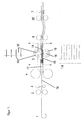
- fig 1 shows a machine for the fabrication of a filter in accordance with the invention
- fig 2 a detail of the machine and the fabrication respectively
- fig 3 a top view of a distance element according to the invention
- fig 4 a section through a finished filter
- fig 5 another embodiment of the distance element
- fig 6 an additional version of the distance element in accordance with the invention
- fig 7 how this is mounted
- fig 8 a cross section through the filter made in this way
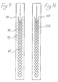
- amd fig 9 amd 10 two additional distance elements accoding to the invention.
- the filter material is fed from two rolls 4 towards a welding station 5. From an additional roll 1 distance element material of foil or sheet material is fed in between two rolls 2 that mill or punch away rectangular openings 10 (see fig 3), so that the distance material temporarily receives the shape of an endless net band constituted of longitudinal strips 8 and cross connections with intermediate openings 10. As an extension of the left edge of the cross connections a cut 11 extends a short distance (corresponding to slightly more than the width of the connection 9) into the strips 8. A subsequent punch 3 then cuts slots 12 in the strips 8 achieving an extension 13 of the cross connections 9 so that U-shaped connections are achieved between adjacent strips. By letting the punch cut differently deep differing total lengths for the U-shaped connections is achieved.
- the part of the distance material shown in fig 3 corresponds to a filter bag with long connections to the right adjacent to the opening of the filter.
- dollies 14 and 15 are arranged as is apparent from fig 1 and 2 above and below the distance material 16.
- the dollies have as is apparent from fig 1b the shape of crosswise arranged combs with broader openings between the teeth than these are broad and are relative each other displaced laterally (fig 2).
- the filter material 17 is fed past the dollies over and under these respectively.
- weld rolls 18 with flanges 19 are arranged.
- the flanges 19 of the rolls 18 as well as the "teeth" of the dollies are located corresponding to the longitudinal strips 8 of the distance material.
- the flanges 19 press the filter material 17. against the dollies 14 and 15 with the distance material therebetween. Ultra sound is fed to the rolls so that distance material and filter material is welded together along the strips 8.
- the connected material is drawn from the dollies, that so to say extends into the filter, further by rolls 6 t a combined separating and welding station 7 where the material step-wise is fed forwards by rolls 20 and is welded along the edges and also separated into individual bags. That is the welded bags are welded in the bottom at the same time as they are cut away from the upper end of the next filter bag.
- the filter bags are made with their openings turned in the running direction of the filter material during the fabrication either forwards or backwards depending on the orientation of the distance elements.
- FIG. 5 another distance element according to the invention is described constituted of longitudinal strips 28 connected with V-shaped cross connections 19.
- the V-shaped connections are differently sharply angled. In the part furthest down (in the filter fold or bag) the angle is very obtuse and consequently the length of the connection between the strips only slightly longer than the distance between the strips. With increasing distance upwards in the filter, that is upwards on the side, the angles become sharper, that is the length of the connections increase. This means that when the has been made the connections will constitute distance elements between the sides of the filter with increasing distance towards the opening side of the filter.
- the longitudinal strips run in the feed direction of the filter material and the distance material can be used in the installation described in connection with fig 1 and 2.
- bands 21 of distance element with a look corresponding to that shown in fig 6 is welded to opposite sides of the filter material 22, for instance by being bent to a half circular channel that is guided along a dolly 23 at the same time as welding takes place with two rolls 24.
- the cross connections 25 in the band then define the distance between the sides of the filter. This gives the appearance that is shown in fig 7 that is the distance connections are perpendicular to the filter material.
- bands 91 punched or cut as is shown in fig 9 may be used.
- cross connections 92 with different lengths are achieved due to different angles for the cuts 93. Since the cross connections 92 are connected to each other with a centrally arranged bridge 94 a much more stable strip is obtained much facilitating the machine mounting.
- the central connecting bridge can be used to contract the filter in the loser end of the filter. Since the filter in the upper end is forced open already by the mounting in a frame the upper cross connections will pull the central bridge upwards and if the connections in the lower end of the filter initially for instance are essentially straight this vertical pull upwards will reduce the width here pulling the sides of the filter closer together.
- the bridge or bridges In order to allow the vertical movement at straightening of the connections the bridge or bridges must be interrupted at top and bottom but still a far more controllable and more easily handled distance element is obtained, considerably facilitating fabrication.
- a longitudinal vertical slot is arranged allowing the separation of the edges of the band but without reduction of the stability. Furthermore small deviations in the vertical position of he distance band at mounting will not be critical.
- the distance element band that during the welding is pulled forwards is due to the continuous edges and stable bridging stable until the mounting has been completed and the distance element and filter material are cut into the individual filter bags.
- the invented method need not to include bands running in the length direction of the material webs but fixing can instead take place along bands that run transversely in relation to the material webs, preferably the welding or fixing is intermittent and does not need to be in the shape of a line but may even be arranged as points.
- the filter bags have to be arranged in the above described manner but instead one can consider letting the filter bags have their openings towards an edge of the webs. In this way it is even possible with simple machine mounting of bag lists or rims at the edges of the edges of the bags to be.
- the bridges or connections in the distance material is preferably shaped considering how the sides of the filter bags move at the separation from the position at fabrication to the position of mounting.
- connection making openings or special openings in this can be detected by for instance photo cells in order to synchronize the strip material with the welding of the filter bags.
Landscapes
- Chemical & Material Sciences (AREA)
- Chemical Kinetics & Catalysis (AREA)
- Filtering Materials (AREA)
- Filtering Of Dispersed Particles In Gases (AREA)
- Fluid-Pressure Circuits (AREA)
- Control Of Throttle Valves Provided In The Intake System Or In The Exhaust System (AREA)
- Centrifugal Separators (AREA)
- Separation Using Semi-Permeable Membranes (AREA)
Abstract
Description
- In order to be able to filtrate the large amounts of air that may be possible in for instance air condition installations it is known to use folded filters with a very great depth. These filters are sometimes called bag-filters since they can be considered as an amount of bags located at each other. In addition to the achieving of a large area for the filter material in this way the filter bags can at transport and storage be folded, which in particular is a saying transport-wise since the filter in the shape that it has when it is used is particularly bulky. As a result of the great areas in the separate bags these however have a considerable tendency to be blown up so that the triangular cross section shape desired for a good flow is easily lost. In order to counteract this it is known to sew fast threads cross-wise through the bag. This has no negative effect on the foldability of the filters. The sewing fast of threads in the filter material may however easily lead to damages in this either directly at the sewing or later when the filter is subjected to a load. Primarily these damages may result in leakages. why glue usually is applied as seal and security. In other words it is a question of comparatively many measures at the fabrication of these filters and in particular the manual effort will become comparatively large. Furthermore the use of glue makes impossible the ambition of a material as homogenous as possible in consideration of the coming destruction or recycling.
- In view of the above problems at filters of this kind the object of the invention is to achieve a filter and a fabrication method for this respectively that can be executed simpler, faster, and with a more complete homogeneity of material.
- In accordance with the invention the object of the invention is achieved by welding, between the opposed filter material sides of the filter bag, distance elements that then at the use of the filter can be extended to a different degree at different locations in the filter. In particular the distance material can consist of sheet material with openings, for instance with a shape in principal corresponding to a ladder but where the separate steps from being entirely straight in one end of the distance element become increasingly bent or V-shaped towards the other end. Since the connecting steps are longer in one end the longitudinal parts of the ladder can be pulled apart to different degrees so that a narrowing or widening ladder is obtained, dependent on in which direction it is viewed. By welding a ladder of sheet material eith one longitudinal part to the filter material on one side of the filter bag and the other longitudinal part of the ladder to the other the distance elements can at the welding be held with the longitudinal parts on the same distance, while at the blowing up of the filter the separate steps or connections are extended so that the intended shape of the filter is defined and maintained. The welding of the distance material can take place with filter material and distance material lying essentially flat and close to each other which facilitates the relative fixing before the welding. In addition to the simple welding method obtained in this way for the welding of the distance elements it is also easy to adapt the fabrication to differently wide bags since one quite simply changes the distance material sheet to one with shorter or longer extendable connections.
- By the arrangement of in particular a distance element sheet over the entire depth of the filter bag it is possible to arrange the desired number of connections between the opposed sides of the bag by connecting alternating "longitudinal ladder parts" with the sides of the filter bag. In this way the distance element connection will not extend perpendicular to the filter material but instead a zigzag shaped framework will be obtained with obliquely or angled connections or bridges between the sides of the filter fold.
- At the known filters where the distances extend straight through the filters against the filter material areas, when the filter is subjected to a load, depressions are easily obtained corresponding to the locations of the cross connections. This means that the outlet channels for the filter become somewhat more narrow than the inlet channels, which possibly must be compensated by making the transverse distances shorter. It is however also at the invention possible to obtain a deviation from the desired plane areas due to the flexibility of the filter material. Since the distances at the invention runs in zigzag the filter rather receives a tendency to wave shape but with a more constant distance in the cross direction. This wave shape can be used to stiffen the filter and is preferably arranged cross-wise in relation to the flow direction. By making close bags identical the flow conditions on the inlet side as well as on the outlet side can be made very uniform. The wave shape can also be used to increase the filter area.
- Within the frame of the inventive thought one can consider to arrange the welded strips in relation to the filter material either running in the depth direction of the filter or cross-wise or perhaps in other directions or pattern or perhaps only in the shape of points. In all cases the connections can be made shorter close to the bottom and longer in the upper ends of the filter bags despite the welding being carried out with the filter material webs on a constant distance from each other.
- The material in the distance elements that are welded between the filter material may have the same chemical composition as the filter material but be constituted by a comparatively thin foil from which material has been punched so that bent, V-shaped or zigzag shaped foil bands are obtained as distances (also other shapes may give the same result).
- Sine the invented method allows continuous machine fabrication of filter bags by means of welding a good quality is obtained at a low cost and a minimum of manual work.
- Even if above dominantly welding has been mentioned the invention may also function with other types of binding, as for instance gluing, seams, heat treatment etc. Likewise the distance elements may have different shape as long as they at use result in the desired for instance differently long connections. The welding to the sides of the filter need not to be along lines but may instead be in points. If the number of cross connections that is required is small or if these should be widely spread the distance element sheets or the web may also include parts that via easily separable extra connections are connected to the parts that are to be welded to the filter material and thereby holds the distance material in the right position until its welded. When the welding has taken place the separable part may be drawn loose from the welded parts and removed from the filter.
- The distance elements can be of filter material, thin foil, net or a nonwoven material from which has been punched, cut, burnt or in some other way suitable connections with different lengths have been achieved.
- Additional advantages and characteristics of the invention are apparent from the following description of preferred embodiments of the invention shown in the drawings. In the drawings fig 1 shows a machine for the fabrication of a filter in accordance with the invention, fig 2 a detail of the machine and the fabrication respectively, fig 3 a top view of a distance element according to the invention, fig 4 a section through a finished filter, fig 5 another embodiment of the distance element , fig 6 an additional version of the distance element in accordance with the invention, fig 7 how this is mounted and fig 8 a cross section through the filter made in this way, amd fig 9
amd 10 two additional distance elements accoding to the invention. - In the machine shown in fig 1 for the fabrication of filters, the filter material is fed from two
rolls 4 towards awelding station 5. From anadditional roll 1 distance element material of foil or sheet material is fed in between tworolls 2 that mill or punch away rectangular openings 10 (see fig 3), so that the distance material temporarily receives the shape of an endless net band constituted oflongitudinal strips 8 and cross connections withintermediate openings 10. As an extension of the left edge of the cross connections acut 11 extends a short distance (corresponding to slightly more than the width of the connection 9) into thestrips 8. Asubsequent punch 3 then cutsslots 12 in thestrips 8 achieving anextension 13 of thecross connections 9 so that U-shaped connections are achieved between adjacent strips. By letting the punch cut differently deep differing total lengths for the U-shaped connections is achieved. The part of the distance material shown in fig 3 corresponds to a filter bag with long connections to the right adjacent to the opening of the filter.
In thewelding station 5dollies distance material 16. The dollies have as is apparent from fig 1b the shape of crosswise arranged combs with broader openings between the teeth than these are broad and are relative each other displaced laterally (fig 2). Thefilter material 17 is fed past the dollies over and under these respectively. Above and below respectively the fedfilter material 17weld rolls 18 withflanges 19 are arranged. Theflanges 19 of therolls 18 as well as the "teeth" of the dollies are located corresponding to thelongitudinal strips 8 of the distance material. Theflanges 19 press thefilter material 17. against thedollies strips 8. - After the welding the connected material is drawn from the dollies, that so to say extends into the filter, further by
rolls 6 t a combined separating and welding station 7 where the material step-wise is fed forwards byrolls 20 and is welded along the edges and also separated into individual bags. That is the welded bags are welded in the bottom at the same time as they are cut away from the upper end of the next filter bag. In the shown case the filter bags are made with their openings turned in the running direction of the filter material during the fabrication either forwards or backwards depending on the orientation of the distance elements. - When the rolls stand still during the welding and cutting the material hangs in an increasing bow between the
rolls - Since the U-shaped connections have different lengths depending on how deeply they are situated in the filter its triangular cross section is supported in the desired way. The connections are at the use of the filter drawn out and become straight with varying length so that the cross section shown in fig 4 is obtained.
- In fig 5 another distance element according to the invention is described constituted of
longitudinal strips 28 connected with V-shaped cross connections 19. The V-shaped connections are differently sharply angled. In the part furthest down (in the filter fold or bag) the angle is very obtuse and consequently the length of the connection between the strips only slightly longer than the distance between the strips. With increasing distance upwards in the filter, that is upwards on the side, the angles become sharper, that is the length of the connections increase. This means that when the has been made the connections will constitute distance elements between the sides of the filter with increasing distance towards the opening side of the filter. The longitudinal strips run in the feed direction of the filter material and the distance material can be used in the installation described in connection with fig 1 and 2. - In order to ensure that the longitudinal strips remain in the right position laterally these may partly be subjected to a certain tension in the length direction but in addition to this transverse uncut connection may exist for lateral support at the parts that correspond to the bottoms of the filter bags, that is furthest to the left in fig 3 and furthest to the right in fig 3.
- As is apparent form fig 3 and 5 distance element connections may be achieved evenly distributed and comparatively closely over the surface of the filter securing a good continuity over the filter that thus will yield good flow conditions. The present internal connections result in so little flow resistance that the flow conditions are not effected in any degree to speak of.
- As an alternative to the above described method one can instead consider that bands 21 of distance element with a look corresponding to that shown in fig 6 is welded to opposite sides of the
filter material 22, for instance by being bent to a half circular channel that is guided along adolly 23 at the same time as welding takes place with tworolls 24. Thecross connections 25 in the band then define the distance between the sides of the filter. This gives the appearance that is shown in fig 7 that is the distance connections are perpendicular to the filter material. - At the method described with reference to fig 6
bands 91 punched or cut as is shown in fig 9 may be used. Here crossconnections 92 with different lengths are achieved due to different angles for thecuts 93. Since thecross connections 92 are connected to each other with a centrally arranged bridge 94 a much more stable strip is obtained much facilitating the machine mounting. - If so desired the central connecting bridge can be used to contract the filter in the loser end of the filter. Since the filter in the upper end is forced open already by the mounting in a frame the upper cross connections will pull the central bridge upwards and if the connections in the lower end of the filter initially for instance are essentially straight this vertical pull upwards will reduce the width here pulling the sides of the filter closer together.
- In order to increase the stability for the distance element bands further several vertical bridges may be arranged so that a net like structure is obtained.
- In order to allow the vertical movement at straightening of the connections the bridge or bridges must be interrupted at top and bottom but still a far more controllable and more easily handled distance element is obtained, considerably facilitating fabrication.
- In the part of the distance element that in the ready filter is located at the top of the filter folds a longitudinal vertical slot is arranged allowing the separation of the edges of the band but without reduction of the stability. Furthermore small deviations in the vertical position of he distance band at mounting will not be critical. The distance element band that during the welding is pulled forwards is due to the continuous edges and stable bridging stable until the mounting has been completed and the distance element and filter material are cut into the individual filter bags.
- In fig 10 is shown a
distance element strip 101 with v-shapedslots 102 but without central bridging. - The invented method need not to include bands running in the length direction of the material webs but fixing can instead take place along bands that run transversely in relation to the material webs, preferably the welding or fixing is intermittent and does not need to be in the shape of a line but may even be arranged as points. Nor do the filter bags have to be arranged in the above described manner but instead one can consider letting the filter bags have their openings towards an edge of the webs. In this way it is even possible with simple machine mounting of bag lists or rims at the edges of the edges of the bags to be.
- The bridges or connections in the distance material is preferably shaped considering how the sides of the filter bags move at the separation from the position at fabrication to the position of mounting. By means of the distance element according to the invention and the mounting method respectively a very large freedom in the choice of the shaping otherwise is obtained due to its great adaptability so that a very rational fabrication can be achieved.
- Since the strip constituting the strip is punched one can also consider that the connection making openings or special openings in this can be detected by for instance photo cells in order to synchronize the strip material with the welding of the filter bags.
Claims (11)
- Method for the achieving of connections between opposing sides in a filter fold or filter bag, characterized in that between the opposed sides of the filter material is arranged a distance material of punched material that is welded in points or along lines to the two filter material sides so that the distance material at these points or lines either is fastened to one filter side or the other and that the distance material includes connections or bridges between the parts that are welded to the different filter sides, which bridges are punched from the distance material so that they at the use of the filter can be drawn out and constitute essentially transverse distance elements.
- Method according to claim 1, characterized in that the connections or bridges have varying length according to the location over the filter so that the filter bag can be given a narrowing contour.
- Method according to claim 1 or 2, characterized in that the distance element along alternating lines are welded continuously to two filter material webs that then in the length direction are divided into separate filters.
- Filter constituted by opposed sides of filter material that are held together by intermediate distance elements of sheet material that has been welded to both sides of filter material characterized in that between the welding points connections are arranged that are curved or angled in the plane of the sheet material so that they at the use of the filter can be drawn out or extended to a greater length than the distance between the welds at the welding.
- Filter according to claim 4, characterized in that the connections have different length to provide a narrowing filter cross section.
- Distance element for the welding to two opposite filter material surfaces for the making of an intermediate connection, characterized in that the distance element includes curved or angled bridges between fastening points on the different filter surfaces so that the distance between the filter surfaces are controlled by the length of the extended bridges.
- Distance element according to claim 6, characterized in that it comprises a sheet with approximately the same area as the dimensions of the dimensions of the filter fold or bag.
- Distance element according to claim 6, characterized in that it includes connections or bridges with different lengths in extended condition for the achieving of narrowing filter folds or bags.
- Distance element characterized in that it is constituted by strips that between their two longitudinal edges are provided with connecting bridges with different lengths so that the distance elements when welded with opposed edges to opposed filter surfaces give a narrowing filter shape.
- device for the execution of the method according to claim 1, characterized in that it includes two comblike dollies, displaced relative each other and arranged so that a distance element can be entered between them and on each side of the pair of dollies are flange provided rolls arranged for welding,for instance with ultra sound, of between dollies and rolls fed filter material that is welded to the distance material.
- Distance element, characterized in that it is provided with cross connections with different extended lengths and that the cross connections are connected to each other in larger or smaller groups by one or several bridges, for instance one centrally located or several for instance in a symmetric pattern.
Priority Applications (1)
| Application Number | Priority Date | Filing Date | Title |
|---|---|---|---|
| DK99850056T DK0951932T3 (en) | 1998-04-09 | 1999-04-06 | Filter and process for making this |
Applications Claiming Priority (2)
| Application Number | Priority Date | Filing Date | Title |
|---|---|---|---|
| SE9801249 | 1998-04-09 | ||
| SE9801249A SE522449C2 (en) | 1998-04-09 | 1998-04-09 | Method for making connections between opposite sides of a filter fold, filters having such connections and spacer elements and apparatus for carrying out the method |
Publications (3)
| Publication Number | Publication Date |
|---|---|
| EP0951932A2 EP0951932A2 (en) | 1999-10-27 |
| EP0951932A3 EP0951932A3 (en) | 2000-01-26 |
| EP0951932B1 true EP0951932B1 (en) | 2004-06-23 |
Family
ID=20410910
Family Applications (1)
| Application Number | Title | Priority Date | Filing Date |
|---|---|---|---|
| EP99850056A Expired - Lifetime EP0951932B1 (en) | 1998-04-09 | 1999-04-06 | Filter and method for the fabrication thereof |
Country Status (8)
| Country | Link |
|---|---|
| US (1) | US6306188B1 (en) |
| EP (1) | EP0951932B1 (en) |
| AT (1) | ATE269753T1 (en) |
| DE (1) | DE69918213T2 (en) |
| DK (1) | DK0951932T3 (en) |
| MY (1) | MY123206A (en) |
| NO (1) | NO318667B1 (en) |
| SE (1) | SE522449C2 (en) |
Families Citing this family (2)
| Publication number | Priority date | Publication date | Assignee | Title |
|---|---|---|---|---|
| US8292981B2 (en) * | 2007-11-07 | 2012-10-23 | Oskar Air Products, Inc. | Low maintenance air cleaning system for welding chambers |
| US9700846B2 (en) * | 2014-12-05 | 2017-07-11 | Rorus Inc. | Fluid purification device with flexible housing |
Family Cites Families (7)
| Publication number | Priority date | Publication date | Assignee | Title |
|---|---|---|---|---|
| US5066319A (en) * | 1989-02-08 | 1991-11-19 | Lippold Hans Joachim | Filter cartridge |
| US5215609A (en) * | 1991-12-20 | 1993-06-01 | Sanders Scott L | Continuous process for producing ultrasonically welded air filters |
| US5156661A (en) * | 1992-01-31 | 1992-10-20 | Pall Corporation | Bag filter with thermoplastic tape-sealed sewn seam |
| DE4345122A1 (en) * | 1993-12-30 | 1995-07-06 | Detroit Holding Ltd | Process for manufacturing a filter insert |
| US5846360A (en) * | 1997-01-09 | 1998-12-08 | Gil; George | Filter and method and apparatus for manufacture thereof |
| US5928396A (en) * | 1997-12-31 | 1999-07-27 | Aaf International | Pocket filter and method and apparatus for making the same |
| US6010548A (en) * | 1998-01-30 | 2000-01-04 | Freudenberg Nonwovens Limited Partnership | Spaced pocket filter assembly and method of manufacturing same |
-
1998
- 1998-04-09 SE SE9801249A patent/SE522449C2/en not_active IP Right Cessation
-
1999
- 1999-04-06 EP EP99850056A patent/EP0951932B1/en not_active Expired - Lifetime
- 1999-04-06 DK DK99850056T patent/DK0951932T3/en active
- 1999-04-06 AT AT99850056T patent/ATE269753T1/en not_active IP Right Cessation
- 1999-04-06 DE DE69918213T patent/DE69918213T2/en not_active Expired - Lifetime
- 1999-04-06 US US09/286,854 patent/US6306188B1/en not_active Expired - Lifetime
- 1999-04-08 MY MYPI99001354A patent/MY123206A/en unknown
- 1999-04-08 NO NO19991658A patent/NO318667B1/en not_active IP Right Cessation
Also Published As
| Publication number | Publication date |
|---|---|
| DK0951932T3 (en) | 2004-11-01 |
| DE69918213T2 (en) | 2005-06-30 |
| NO991658L (en) | 1999-10-11 |
| EP0951932A2 (en) | 1999-10-27 |
| SE9801249L (en) | 1999-10-10 |
| NO991658D0 (en) | 1999-04-08 |
| SE522449C2 (en) | 2004-02-10 |
| SE9801249D0 (en) | 1998-04-09 |
| EP0951932A3 (en) | 2000-01-26 |
| ATE269753T1 (en) | 2004-07-15 |
| NO318667B1 (en) | 2005-04-25 |
| MY123206A (en) | 2006-05-31 |
| US6306188B1 (en) | 2001-10-23 |
| DE69918213D1 (en) | 2004-07-29 |
Similar Documents
| Publication | Publication Date | Title |
|---|---|---|
| DE60038639T2 (en) | Plastic bag | |
| US5496251A (en) | Method and apparatus for manufacturing a shell-shaped package, and such shell-shaped package | |
| DE3700914C2 (en) | ||
| EP0814890B1 (en) | Gas filter unit | |
| US20130031885A1 (en) | Pocket filter assembly | |
| CA2034867A1 (en) | Filter insert formed as a pleated pack and a process for its production | |
| DE3335551A1 (en) | METHOD FOR PRODUCING PARTLY SEPARATE MULTIPLE BAGS | |
| DE2354051C2 (en) | Device for applying tear tapes to a moving web of packaging material | |
| DE69719287T2 (en) | container carrier | |
| DE1407932B2 (en) | FLAT FILTER BAG WITH AN EDGE RECTANGULAR CROSS-SECTION AND PROCESS FOR THEIR PRODUCTION | |
| EP0951932A2 (en) | Filter and method for the fabrication thereof | |
| US6159316A (en) | Method of making multi-pocket filter | |
| EP0348823B1 (en) | Method and device for manufacturing bags with thermoplastic pull strings | |
| EP0733010A1 (en) | Bag forming, filling and sealing machine | |
| EP3159446A2 (en) | Device for thermal treatment of a textile web | |
| DE1607668B2 (en) | Gas filter | |
| JP2703504B2 (en) | Filler for permeation filter for fluid treatment and method for producing the same | |
| FI108703B (en) | Cutting table cover and method of making it | |
| DE10021470A1 (en) | Tubular bag packing machine has foil supply device and transport means for wrapped and unwrapped objects and with welding members and cross stretchers to pull foil transversely to remove folds | |
| DE2712510A1 (en) | METHOD AND DEVICE FOR THE PRODUCTION OF PLASTIC BAGS OR SACKS | |
| DE19829100C1 (en) | Folded air or gas filter made of a web of thermoplastic fleece fibers | |
| US4945612A (en) | System and a method for joining the ends of a band-shaped elongate element | |
| US5151151A (en) | Pleating machine for dual fluted shade | |
| DE3742911C2 (en) | Method and device for expanding tobacco material | |
| GB2333249A (en) | Ultrasonically welded air filter element |
Legal Events
| Date | Code | Title | Description |
|---|---|---|---|
| PUAI | Public reference made under article 153(3) epc to a published international application that has entered the european phase |
Free format text: ORIGINAL CODE: 0009012 |
|
| AK | Designated contracting states |
Kind code of ref document: A2 Designated state(s): AT BE CH CY DE DK ES FI FR GB GR IE IT LI LU MC NL PT SE |
|
| AX | Request for extension of the european patent |
Free format text: AL;LT;LV;MK;RO;SI |
|
| PUAL | Search report despatched |
Free format text: ORIGINAL CODE: 0009013 |
|
| RIC1 | Information provided on ipc code assigned before grant |
Free format text: 7B 01D 46/06 A, 7B 01D 46/52 B, 7B 01D 29/07 B |
|
| AK | Designated contracting states |
Kind code of ref document: A3 Designated state(s): AT BE CH CY DE DK ES FI FR GB GR IE IT LI LU MC NL PT SE |
|
| AX | Request for extension of the european patent |
Free format text: AL;LT;LV;MK;RO;SI |
|
| 17P | Request for examination filed |
Effective date: 20000726 |
|
| AKX | Designation fees paid |
Free format text: AT BE CH CY DE DK ES FI FR GB GR IE IT LI LU MC NL PT SE |
|
| GRAP | Despatch of communication of intention to grant a patent |
Free format text: ORIGINAL CODE: EPIDOSNIGR1 |
|
| GRAS | Grant fee paid |
Free format text: ORIGINAL CODE: EPIDOSNIGR3 |
|
| GRAA | (expected) grant |
Free format text: ORIGINAL CODE: 0009210 |
|
| AK | Designated contracting states |
Kind code of ref document: B1 Designated state(s): AT BE CH CY DE DK ES FI FR GB GR IE IT LI LU MC NL PT SE |
|
| PG25 | Lapsed in a contracting state [announced via postgrant information from national office to epo] |
Ref country code: ES Free format text: LAPSE BECAUSE OF FAILURE TO SUBMIT A TRANSLATION OF THE DESCRIPTION OR TO PAY THE FEE WITHIN THE PRESCRIBED TIME-LIMIT Effective date: 20040623 Ref country code: AT Free format text: LAPSE BECAUSE OF FAILURE TO SUBMIT A TRANSLATION OF THE DESCRIPTION OR TO PAY THE FEE WITHIN THE PRESCRIBED TIME-LIMIT Effective date: 20040623 |
|
| REG | Reference to a national code |
Ref country code: GB Ref legal event code: FG4D |
|
| REG | Reference to a national code |
Ref country code: CH Ref legal event code: EP |
|
| REG | Reference to a national code |
Ref country code: IE Ref legal event code: FG4D |
|
| REF | Corresponds to: |
Ref document number: 69918213 Country of ref document: DE Date of ref document: 20040729 Kind code of ref document: P |
|
| PG25 | Lapsed in a contracting state [announced via postgrant information from national office to epo] |
Ref country code: SE Free format text: LAPSE BECAUSE OF FAILURE TO SUBMIT A TRANSLATION OF THE DESCRIPTION OR TO PAY THE FEE WITHIN THE PRESCRIBED TIME-LIMIT Effective date: 20040923 Ref country code: GR Free format text: LAPSE BECAUSE OF FAILURE TO SUBMIT A TRANSLATION OF THE DESCRIPTION OR TO PAY THE FEE WITHIN THE PRESCRIBED TIME-LIMIT Effective date: 20040923 |
|
| REG | Reference to a national code |
Ref country code: DK Ref legal event code: T3 |
|
| ET | Fr: translation filed | ||
| PG25 | Lapsed in a contracting state [announced via postgrant information from national office to epo] |
Ref country code: LU Free format text: LAPSE BECAUSE OF NON-PAYMENT OF DUE FEES Effective date: 20050406 Ref country code: CY Free format text: LAPSE BECAUSE OF FAILURE TO SUBMIT A TRANSLATION OF THE DESCRIPTION OR TO PAY THE FEE WITHIN THE PRESCRIBED TIME-LIMIT Effective date: 20050406 |
|
| PLBE | No opposition filed within time limit |
Free format text: ORIGINAL CODE: 0009261 |
|
| STAA | Information on the status of an ep patent application or granted ep patent |
Free format text: STATUS: NO OPPOSITION FILED WITHIN TIME LIMIT |
|
| PG25 | Lapsed in a contracting state [announced via postgrant information from national office to epo] |
Ref country code: MC Free format text: LAPSE BECAUSE OF NON-PAYMENT OF DUE FEES Effective date: 20050430 |
|
| 26N | No opposition filed |
Effective date: 20050324 |
|
| PG25 | Lapsed in a contracting state [announced via postgrant information from national office to epo] |
Ref country code: PT Free format text: LAPSE BECAUSE OF NON-PAYMENT OF DUE FEES Effective date: 20041123 |
|
| REG | Reference to a national code |
Ref country code: FR Ref legal event code: PLFP Year of fee payment: 18 |
|
| REG | Reference to a national code |
Ref country code: FR Ref legal event code: PLFP Year of fee payment: 19 |
|
| PGFP | Annual fee paid to national office [announced via postgrant information from national office to epo] |
Ref country code: NL Payment date: 20170419 Year of fee payment: 19 |
|
| PGFP | Annual fee paid to national office [announced via postgrant information from national office to epo] |
Ref country code: GB Payment date: 20170419 Year of fee payment: 19 Ref country code: DE Payment date: 20170419 Year of fee payment: 19 Ref country code: CH Payment date: 20170419 Year of fee payment: 19 Ref country code: FR Payment date: 20170419 Year of fee payment: 19 Ref country code: DK Payment date: 20170419 Year of fee payment: 19 Ref country code: IE Payment date: 20170421 Year of fee payment: 19 |
|
| PGFP | Annual fee paid to national office [announced via postgrant information from national office to epo] |
Ref country code: FI Payment date: 20170412 Year of fee payment: 19 Ref country code: IT Payment date: 20170420 Year of fee payment: 19 Ref country code: BE Payment date: 20170419 Year of fee payment: 19 |
|
| REG | Reference to a national code |
Ref country code: DE Ref legal event code: R119 Ref document number: 69918213 Country of ref document: DE |
|
| REG | Reference to a national code |
Ref country code: DK Ref legal event code: EBP Effective date: 20180430 |
|
| REG | Reference to a national code |
Ref country code: CH Ref legal event code: PL |
|
| REG | Reference to a national code |
Ref country code: NL Ref legal event code: MM Effective date: 20180501 |
|
| REG | Reference to a national code |
Ref country code: BE Ref legal event code: MM Effective date: 20180430 |
|
| GBPC | Gb: european patent ceased through non-payment of renewal fee |
Effective date: 20180406 |
|
| REG | Reference to a national code |
Ref country code: IE Ref legal event code: MM4A |
|
| PG25 | Lapsed in a contracting state [announced via postgrant information from national office to epo] |
Ref country code: NL Free format text: LAPSE BECAUSE OF NON-PAYMENT OF DUE FEES Effective date: 20180501 Ref country code: FI Free format text: LAPSE BECAUSE OF NON-PAYMENT OF DUE FEES Effective date: 20180406 Ref country code: DE Free format text: LAPSE BECAUSE OF NON-PAYMENT OF DUE FEES Effective date: 20181101 |
|
| PG25 | Lapsed in a contracting state [announced via postgrant information from national office to epo] |
Ref country code: LI Free format text: LAPSE BECAUSE OF NON-PAYMENT OF DUE FEES Effective date: 20180430 Ref country code: GB Free format text: LAPSE BECAUSE OF NON-PAYMENT OF DUE FEES Effective date: 20180406 Ref country code: CH Free format text: LAPSE BECAUSE OF NON-PAYMENT OF DUE FEES Effective date: 20180430 Ref country code: BE Free format text: LAPSE BECAUSE OF NON-PAYMENT OF DUE FEES Effective date: 20180430 |
|
| PG25 | Lapsed in a contracting state [announced via postgrant information from national office to epo] |
Ref country code: IT Free format text: LAPSE BECAUSE OF NON-PAYMENT OF DUE FEES Effective date: 20180406 Ref country code: IE Free format text: LAPSE BECAUSE OF NON-PAYMENT OF DUE FEES Effective date: 20180406 Ref country code: FR Free format text: LAPSE BECAUSE OF NON-PAYMENT OF DUE FEES Effective date: 20180430 |
|
| PG25 | Lapsed in a contracting state [announced via postgrant information from national office to epo] |
Ref country code: DK Free format text: LAPSE BECAUSE OF NON-PAYMENT OF DUE FEES Effective date: 20180430 |