The present invention relates to apparatus for
sensing the level of contents in a container.
There is known from disclosures such as EP-A-0444173
a type of apparatus for sensing the level of contents in
a container in which a probe is energised into vibration
by a piezoelectric driving crystal, and vibrations in the
probe are monitored by a receiving crystal. The crystals
are separated from the probe by a diaphragm. The
apparatus is disposed for use such that the probe
projects into a container. The level of contents in the
container can be determined because the vibration of the
probe, and hence the signal generated by the receiving
crystal, changes in dependance on whether the probe is
submerged within or is clear of the contents of the
container. Apparatus of this type is suitable for use
with solid particular or liquid contents.
A particular technical difficulty associated with
apparatus of this type arises from the need to
mechanically couple the crystals to the probe such that
vibration of the driving crystal is efficiently
transmitted to the probe, and such that vibration in the
probe is transmitted efficiently to the receiving
crystal. It is an aim of the present invention to
provide apparatus for sensing the level of contents in a
container of the type described in the last-preceding
paragraph in which transmission of vibration between the
probe and the crystals is achieved in an efficient
manner.
One particular problem with prior art arrangements,
for example as illustrated in GB-A-2150292 has been
identified by the present applicant. It is that the
crystals are supported on the diaphragm such that
vibration of the probe can cause the crystal stack to
vibrate bodily. This is not desirable because bodily
movement does not contribute to generation of an output
signal. To generate a signal, the crystals must be
subject to a compressive force of variable magnitude.
It has also been realised by the applicants that a
potential source of inefficiency in apparatus such as
this arise from the manner in which oscillation of the
probes is converted into modulation of compression within
the crystal stack. In the prior art, such conversion
relies upon transverse oscillation of the probe being
converted into linear oscillation in the stack through
the mechanism of flexure of the diaphragm giving rise to
linear movement of the central region of the diaphragm.
It is proposed that a further increase in effectiveness
of transmission of vibration between the probe and the
crystal stack may be obtainable if the need for this
conversion were avoided.
According to a first aspect of the invention there
is provided apparatus for sensing the level of contents
in a container comprising:
By arranging the actuating arm opposite the probe,
vibration of the probe can be transmitted directly to the
arm, which in turn can transmit vibration directly to the
crystal stack, thereby minimising opportunities for
mechanical loss to occur.
There may be provided one stack which comprises both
driving and receiving transducers. Alternatively, the
driving and the receiving transducers may be provided in
separate stacks.
The or each stack can be used to even greater effect
if two probes are provided disposed symmetrically on the
diaphragm to oscillate in anti-phase. In such an
arrangement, an actuating arm is provided for each probe,
such that each arm effectively acts as the reaction
member for the other arm.
As such, a second aspect of the invention provides
apparatus for sensing the level of contents in a
container comprising:
In general, a stack will have an optimum axis along
which the driving transducer causes a change in length of
the stack and on which forces applied to the stack have
the greatest effect on the output voltage of the
receiving transducer. In embodiments of the first and
second aspects of the invention, the stack is typically
disposed to have its optimum axis generally parallel to
the diaphragm.
The transducers used in either aspect of the
invention may comprise crystals formed from piezoelectric
material, bodies of magnetostrictive material, multi-layered
configurations, or combinations of any of the
above, and/or other materials.
Embodiments of the invention will now be described
in detail, by way of example, and with reference to the
accompanying drawings, in which:
With reference first to figure 1, apparatus for
sensing the level of contents in a container embodying
the invention comprises a body 10. The body 10 is
generally cylindrical, and symmetrical about an axis A.
A threaded region 12 is provided on an outer surface of
the body 10 whereby the body 10 can be secured within a
suitably-threaded aperture in a wall of a container.
When the body 10 is thus secured, a portion of it
(referred to as inner end portion) projects within the
container, and a portion of it (referred to as the outer
end portion) projects out from the container. As
illustrated in Figure 1, the outer end portion is
disposed towards the right of the drawing.
A first part of the outer end region at 14, next to
the threaded region 12 is shaped (in this embodiment with
outwardly directed flats) whereby the body 10 can be
gripped by a tool, such as a spanner, to enable the body
10 to be rotated in order to tighten its threaded region
12 within an aperture.
A cylindrical part 16 of the outer end region is
disposed outwardly of its first part, and has a first
groove 18 formed in it within which a sealing element,
such as an O-ring 19, can be located and a second groove
17 within which a retaining element, such as a circlip
can be retained. An enclosure 20 is carried on the body
10, the enclosure having an aperture in which the
cylindrical part 16 of the outer end region is received
and retained by a retaining element in the second groove
17. A seal is formed between the cylindrical part 16 and
the aperture by the O-ring 19. The purpose of the
enclosure 20 is to provide a suitable environment within
which electronic circuitry required to control the
apparatus may be contained. Alternatively, the
cylindrical part 16 and the aperture may be threaded for
engagement with one another.
Within the body 10 there is an axially-extending
void 30 of circular cross-section which is open at the
outer end.
The apparatus further includes a fork assembly. The
fork assembly comprises a pair of probes 40 formed
integrally with an end closure 42 of the body 10.
Each probe 40 is an elongate component which, in
use, projects into the container. In this embodiments,
the probes 40 are made of metal, but they might
alternatively be formed of other suitable materials
including plastics or ceramic materials.
An inner end portion 44 of each probe 40 is
relatively flat and broad. The inner end portion 44
projects from a relatively narrower shank portion 46.
The shank portion 46 in turn projects from an attachment
portion 48, the attachment portion 48 being of
substantially the same width as the inner end portion 44.
The probes 40 are disposed such that they taper gradually
away from one another, spaced from one another,
symmetrically about the axis A. Their respective inner
end portions 44 face one another.
The end closure 42 is formed of a suitable material,
in this embodiment of metal, in one piece. The end
closure 42 comprises a transverse diaphragm 50 which is
circular in shape and extends transversely of the axis of
the body 10. The probes 40 are fixed to or are an
integral part of the diaphragm 50. A flange 52 projects
from the circumference of the diaphragm 50 in an
direction parallel to the axis A. Each probe 40 is
formed integrally with the diaphragm, for example, in a
one-piece casting, so as to project in a direction
opposite to the flange 52.
Two actuating arms 54,56 project from the diaphragm
50. The actuating arms are formed integrally with the
end closure. Each actuating arm is disposed on the
diaphragm 50 such that it is immediately opposite a
respective one of the probes 40. The actuating arms
54,56 will be described in greater detail below.
The end closure 42 is secured to the body 10 by a
circumferential weld formed between the flange 52 and the
body 10. The weld is formed so as to create a fluid-tight
seal between the body 10 and the end closure 42.
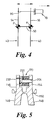
The diaphragm 50 has resilience to enable the probes
to vibrate in a resonant manner, towards and away from
one another, much like a tuning fork. During such
vibration, the diaphragm 50 flexes, such that a central
part of it oscillates substantially linearly along the
axis A, and such that the actuating arms 54,56 oscillate
towards and away from one another. As will be understood
that actuating arms 54,56 and the probes 40 are closely
mechanically coupled to one another. A large amount of
vibrational energy can therefore be transferred from the
probes 40 to the actuating arms 54,56. This oscillation
is shown diagrammatically in Figure 4.
Figure 2 shows the diaphragm 50, actuating arms
54,56 and a transducer assembly of the embodiment of
Figure 1. In this figure, the body has been omitted in
the interest of clarity. Figure 3 shows in greater
detail, and in cross section, the arrangement of the
transducer assembly in this embodiment.
The transducer assembly comprises a stack 70
comprising a plurality of annular components arranged on
a supporting sleeve 82 in alignment along an axis B. The
sleeve 82 has a hollow cylindrical shank portion and a
head portion of larger diameter; it is made of an
insulating material.
The components of the stack (all of which are
generally annular) are arranged on the
sleeve 82 as
follows:
It will be readily understood that each of these
components could be formed from a wide variety of
materials and configurations.
The outer diameter of the shank is selected so as to
be a close fit within the bores of the components,
thereby ensuring that all of the components are
maintained in a substantially coaxial arrangement.
An end of the shank portion projects from the stack
70. A short end portion of the outer diameter of the
shank may be tapered to facilitate assembly of components
onto it.
Each electrode is in electrical communication with
the crystal or crystals next to it within the stack 70.
Connections (not shown) are made to the electrodes 74
whereby an alternating voltage may be applied to the
driving crystal 74 and voltages may be derived from the
receiving crystals 80.
The transducer assembly further comprises a length
of threaded stud 90. A first end of the threaded stud
90 is secured in a threaded bore 92 in a first one of the
actuating arms 54. A thread locking compound is applied
within the bore 92 to prevent loosening of the stud 90.
The stud 90 extends along the axis B, through a bore 94
in a second one of the actuating arms 56, this bore 94
being of sufficiently large diameter that it does not
make contact with the stud 90.
The stack 70 is carried on the stud, with the end of
the shank portion projecting a short way into the bore
94. Its brass support 72 abuts the second actuating arm
56. The stack 70 is then secured under compression by a
washer 96 and a nut 98 applied to the free end of the
stud 90.
Once assembled as described, the stud 90 is under
tension such that the diaphragm 50 adopts a convex shape,
being curved away from the outer end of the body 10. The
stack 70 is clamped in compression between the nut 98 and
the end wall 32 of the body 10. The diaphragm 50 must be
made sufficiently stiff as to resiliently resist
distortion by the forces which this pre-load creates
within the diaphragm 50.
In this embodiment, a second actuating arm 56 has a
first section which projects normally from the diaphragm
50, an intermediate section which is displaced radially
towards the first actuating arm 54, and a third section
(through which the bore 94 is formed) which extends
normally from the diaphragm 50. Thus, the second
actuating arm 56 has a stepped configuration. By this
arrangement, part of the stack 70 can be accommodated
within the step of the actuating arm 56 such that the
amount by which is projects radially beyond the periphery
of the diaphragm 50 is minimised or, more preferably,
such that the stack 70 is disposed within the periphery
of the diaphragm 50.
The first actuating arm 54 may be formed so as to
have a portion (within which the threaded bore 92 is
formed)remote from the diaphragm 50 which is of a
thickness less than a portion adjacent the diaphragm 50.
This permits a greater offset to be formed in the second
actuating arm 56 than would be the case if the first
actuating arm 54 were straight.
The above-described arrangement is such that
vibrational movement of the diaphragm 50 caused by the
probes 40 is transmitted to the actuating arms 54,56.
The actuating arms 54,56 are formed to be sufficiently
rigidly to minimise flexing and thereby to transmit
vibration along their length with as little energy loss
as possible. It will be understood that the effect of
this arrangement is to transmit vibrational energy from
the probes 40 through the actuating arms 54,56 into the
stack 70. Energy is transmitted directly through the
diaphragm 50, thereby minimising the amount of energy
lost. The actuating arms 54,56 and the probes 40 can be
considered to be rigid elongate bodies carried to pivot
about pivot points P within the diaphragm 50, as
illustrated in Figure 4.
A further embodiment of the invention is shown in
Figure 5. As with the first embodiment, actuating arms
154, 156 are provided which transmit vibration forces
from a pair of probes 140. Each actuating arm 154,156 is
stepped, whereby there is a greater distance between them
remote from the diaphragm than there is adjacent the
diaphragm.
In this embodiment, a stack 170 is disposed in
compression between the actuating arms 140. The stack
170 is connected to a first of the actuating arms 154 by
a bolt 200. The bolt 200 passes through the stack 170
and through a threaded bore 204 in the first actuating
arm 154 within which it is secured by application of a
thread locking compound. A bore 202 is also provided in
the second actuating arm 156 through which a head of the
bolt 200 can be reached. It should be noted that the bolt
200 does not connect the stack 170 to the second
actuating arm 156, the bore 202 being wide enough such
that the head of the bolt can pas clearly through it.
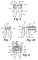
With reference now to Figure 6, a further
alternative embodiment comprises a diaphragm 250, probes
240 and actuating arms 254,256, disposed most generally
as in the last-preceding embodiment, with the
modification that each actuating arm 254,256 is stepped,
whereby there is a lesser distance between them remote
from the diaphragm than there is adjacent the diaphragm.
In this embodiment, two stacks 270, 271 are
provided. These are each clamped to a respective one of
the actuating arms 254,256, and each extends axially away
from the other with its axis generally parallel to the
diaphragm 250. A bolt 300 extends through both of the
stacks 270,271 and through bores in both of the actuating
arms 254,256. A head of the bolt 300 is disposed in a
countersunk recess in a washer 304 to apply force evenly
across an end surface of one of the stacks 270. A nut
306 applied to the bolt 300 applies force evenly across
an end surface of the other of the stacks 271. Thread
locking compound is applied to prevent the nut becoming
separated from the bolt. By tightening the nut, the bolt
300 is placed under tension. This causes each of the two
stacks 270,271 to be compressed against the corresponding
actuating arm 254,256.
In one possible arrangement, one of the stacks 270
comprises driving transducers only while the other stack
271 comprises receiving transducers only. Alternatively,
each stack 270,271 may comprise both types of transducer.
Many variations on these embodiments are possible
within the scope of the invention. For example, the
embodiment of Figure 5 could be modified as shown in
Figure 7. In this modification, the stack 270 is
retained in place between the actuating arms 254, 256
principally by the clamping action which occurs as the
stack 270 is loaded in compression by the actuating arms
254,256. Optionally, retention of the stack 270 can be
enhanced by bonding it to the actuating arms 254,256
and/or by providing some other means extending through
the arms 254,256 to engage the stack, for example set
screws 280 seen in Figure 8, which can be tightened to
pre-load the stack 270.
The arrangement of Figure 8 also includes a stack
housing shoe 282 which is pinned to at least one of the
actuating arms above the stack 270 to protect the stack
and help to retain it in place. The Figure also shows an
example of a stack including a piezo electric ceramic
multi-layer actuator (MLA) 284 in place of the driving
crystal of the other arrangements described. The MLA 284
is held in place in the stack between two retaining pads
286.
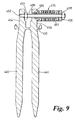
Figures 9 and 10 show two further arrangements.
These are broadly similar to the embodiment of Figure 1,
but it will be seen that the actuating arms 354,356 are
arranged symmetrically about the diaphragm 350, and are
not offset as are the actuating arms of the embodiment of
Figure 1.
Subject to the modification described in the last-preceding
paragraph, the embodiment of Figure 9 is
similar to the embodiment of Figure 1. In this
embodiment, a locking nut 493 is threaded onto the stud
490 between the actuating arms 454,456. The locking nut
493 is positioned to abut the first actuating arm 454 to
resist unscrewing movement of the stud 490 and to enhance
mechanical coupling between the stud 490 and the
actuating arm 454 thereby increasing the amount of
vibrational energy transferred from the actuating arm 454
to the stud 490.
In the embodiment of Figure 10, the stack 370 is
secured by a bolt 390. The head 396 of the bolt 390
engages a brass support 372 of the stack 370. The shaft
of the bolt 390 passes through the stack 370 and through
the second actuating arm 356 such that an end portion of
it is retained in a threaded bore 392 in the first
actuating arm 354.
It will be readily understood that features of
various embodiments described above can be combined in
many alternative configurations to produce further
embodiments of the invention.
The stack, in many embodiments of the invention,
could comprise transducers other than piezoelectric
crystals. For example, in any of the above embodiments,
one or more annular multi-layered configurations could
replace any or all crystals in a stack. Alternatively,
one or more body of a magnetostrictive metal alloy, such
as Terfenol-D (r.t.m) could be used in place of any or
all crystals in a stack.