EP0950821A1 - Threaded rod and strut connector and method - Google Patents
Threaded rod and strut connector and method Download PDFInfo
- Publication number
- EP0950821A1 EP0950821A1 EP99107596A EP99107596A EP0950821A1 EP 0950821 A1 EP0950821 A1 EP 0950821A1 EP 99107596 A EP99107596 A EP 99107596A EP 99107596 A EP99107596 A EP 99107596A EP 0950821 A1 EP0950821 A1 EP 0950821A1
- Authority
- EP
- European Patent Office
- Prior art keywords
- rod
- strut
- head
- set forth
- connector
- Prior art date
- Legal status (The legal status is an assumption and is not a legal conclusion. Google has not performed a legal analysis and makes no representation as to the accuracy of the status listed.)
- Granted
Links
- 238000000034 method Methods 0.000 title claims description 8
- 238000003780 insertion Methods 0.000 claims description 4
- 230000037431 insertion Effects 0.000 claims description 4
- 239000002184 metal Substances 0.000 claims 2
- 238000000926 separation method Methods 0.000 claims 1
- 241000251131 Sphyrna Species 0.000 description 4
- 230000000712 assembly Effects 0.000 description 3
- 238000000429 assembly Methods 0.000 description 3
- 238000010276 construction Methods 0.000 description 2
- 239000011435 rock Substances 0.000 description 2
- 238000004378 air conditioning Methods 0.000 description 1
- 230000006835 compression Effects 0.000 description 1
- 238000007906 compression Methods 0.000 description 1
- 238000009432 framing Methods 0.000 description 1
- 238000009434 installation Methods 0.000 description 1
- 238000009423 ventilation Methods 0.000 description 1
Images

Classifications
-
- F—MECHANICAL ENGINEERING; LIGHTING; HEATING; WEAPONS; BLASTING
- F16—ENGINEERING ELEMENTS AND UNITS; GENERAL MEASURES FOR PRODUCING AND MAINTAINING EFFECTIVE FUNCTIONING OF MACHINES OR INSTALLATIONS; THERMAL INSULATION IN GENERAL
- F16B—DEVICES FOR FASTENING OR SECURING CONSTRUCTIONAL ELEMENTS OR MACHINE PARTS TOGETHER, e.g. NAILS, BOLTS, CIRCLIPS, CLAMPS, CLIPS OR WEDGES; JOINTS OR JOINTING
- F16B37/00—Nuts or like thread-engaging members
- F16B37/04—Devices for fastening nuts to surfaces, e.g. sheets, plates
- F16B37/045—Devices for fastening nuts to surfaces, e.g. sheets, plates specially adapted for fastening in channels, e.g. sliding bolts, channel nuts
-
- F—MECHANICAL ENGINEERING; LIGHTING; HEATING; WEAPONS; BLASTING
- F16—ENGINEERING ELEMENTS AND UNITS; GENERAL MEASURES FOR PRODUCING AND MAINTAINING EFFECTIVE FUNCTIONING OF MACHINES OR INSTALLATIONS; THERMAL INSULATION IN GENERAL
- F16B—DEVICES FOR FASTENING OR SECURING CONSTRUCTIONAL ELEMENTS OR MACHINE PARTS TOGETHER, e.g. NAILS, BOLTS, CIRCLIPS, CLAMPS, CLIPS OR WEDGES; JOINTS OR JOINTING
- F16B2/00—Friction-grip releasable fastenings
- F16B2/02—Clamps, i.e. with gripping action effected by positive means other than the inherent resistance to deformation of the material of the fastening
- F16B2/06—Clamps, i.e. with gripping action effected by positive means other than the inherent resistance to deformation of the material of the fastening external, i.e. with contracting action
- F16B2/065—Clamps, i.e. with gripping action effected by positive means other than the inherent resistance to deformation of the material of the fastening external, i.e. with contracting action using screw-thread elements
-
- F—MECHANICAL ENGINEERING; LIGHTING; HEATING; WEAPONS; BLASTING
- F16—ENGINEERING ELEMENTS AND UNITS; GENERAL MEASURES FOR PRODUCING AND MAINTAINING EFFECTIVE FUNCTIONING OF MACHINES OR INSTALLATIONS; THERMAL INSULATION IN GENERAL
- F16B—DEVICES FOR FASTENING OR SECURING CONSTRUCTIONAL ELEMENTS OR MACHINE PARTS TOGETHER, e.g. NAILS, BOLTS, CIRCLIPS, CLAMPS, CLIPS OR WEDGES; JOINTS OR JOINTING
- F16B7/00—Connections of rods or tubes, e.g. of non-circular section, mutually, including resilient connections
- F16B7/04—Clamping or clipping connections
- F16B7/044—Clamping or clipping connections for rods or tubes being in angled relationship
-
- F—MECHANICAL ENGINEERING; LIGHTING; HEATING; WEAPONS; BLASTING
- F16—ENGINEERING ELEMENTS AND UNITS; GENERAL MEASURES FOR PRODUCING AND MAINTAINING EFFECTIVE FUNCTIONING OF MACHINES OR INSTALLATIONS; THERMAL INSULATION IN GENERAL
- F16B—DEVICES FOR FASTENING OR SECURING CONSTRUCTIONAL ELEMENTS OR MACHINE PARTS TOGETHER, e.g. NAILS, BOLTS, CIRCLIPS, CLAMPS, CLIPS OR WEDGES; JOINTS OR JOINTING
- F16B2200/00—Constructional details of connections not covered for in other groups of this subclass
- F16B2200/40—Clamping arrangements where clamping parts are received in recesses of elements to be connected
-
- F—MECHANICAL ENGINEERING; LIGHTING; HEATING; WEAPONS; BLASTING
- F16—ENGINEERING ELEMENTS AND UNITS; GENERAL MEASURES FOR PRODUCING AND MAINTAINING EFFECTIVE FUNCTIONING OF MACHINES OR INSTALLATIONS; THERMAL INSULATION IN GENERAL
- F16B—DEVICES FOR FASTENING OR SECURING CONSTRUCTIONAL ELEMENTS OR MACHINE PARTS TOGETHER, e.g. NAILS, BOLTS, CIRCLIPS, CLAMPS, CLIPS OR WEDGES; JOINTS OR JOINTING
- F16B2200/00—Constructional details of connections not covered for in other groups of this subclass
- F16B2200/50—Flanged connections
- F16B2200/509—Flanged connections clamped
-
- Y—GENERAL TAGGING OF NEW TECHNOLOGICAL DEVELOPMENTS; GENERAL TAGGING OF CROSS-SECTIONAL TECHNOLOGIES SPANNING OVER SEVERAL SECTIONS OF THE IPC; TECHNICAL SUBJECTS COVERED BY FORMER USPC CROSS-REFERENCE ART COLLECTIONS [XRACs] AND DIGESTS
- Y10—TECHNICAL SUBJECTS COVERED BY FORMER USPC
- Y10T—TECHNICAL SUBJECTS COVERED BY FORMER US CLASSIFICATION
- Y10T403/00—Joints and connections
- Y10T403/70—Interfitted members
- Y10T403/7062—Clamped members
- Y10T403/7064—Clamped members by wedge or cam
- Y10T403/7066—Clamped members by wedge or cam having actuator
- Y10T403/7067—Threaded actuator
Definitions
- This invention relates generally to a connector for threaded rod and strut, and more particularly to the connector, and to a method of installing and adjusting the same.
- Channel or U-shape strut is widely used in the construction industry. It is used to form vertical, horizontal or even angular framing. It may be hung from ceilings or attached to or embedded in walls or ceilings. Conventional struts are U-shape or channel shape, and the legs terminate in a rolled or inturned short radius circular fold so that the inturned legs terminate in an inwardly facing edge. The opening of the channel is thus restricted, and the legs are in the form of two continuous hooks.
- a wide variety of fasteners, hangers or brackets are used to support utilities, such as pipes, conduit, lighting, cable trays, and air conditioning or ventilation duct work, for example.
- a strut nut is normally employed to connect the rod to the strut.
- the strut nut has two parallel grooves in one surface which are designed to seat on the parallel inturned edges of the channel legs.
- the strut nut is usually a machined block rectangular in shape, so that it has a narrow dimension enabling it to be inserted into the channel between the inturned edge legs and rotated 90° to span the edges of the legs. This normally has to be done by hand with the installer's fingers being inserted in the channel and twisting the nut.
- the nuts are often provided with unwieldy compression springs to push the nut from the bottom of the channel once seated to maintain the grooves on the inturned leg edges. Trying to thread a rod into the nut may compress the spring excessively causing the nut to slip and making the proper insertion of the rod difficult.
- the nuts In some arrangements, particularly with square nuts, the nuts have to be inserted or threaded into the end of the channel.
- Square nuts are sometimes used with strut or channel that has a series of holes in the back, with the rod threaded in the nut extending downwardly through the hole. Sometimes the nuts are simply loose in the channel or strut, relying solely only on the weight of the load to keep them in place.
- Some systems use one kind of nut for the open side of the channel or strut, and another for the other or back of the channel.
- a rod can also be secured to a strut using what is known as a hammerhead which seats on the outer turned portion of the strut legs.
- the rod extends through the hammerhead and through the bottom of the strut.
- Conventional nuts and optionally washers are threaded to bear against the hammerhead and bottom of the strut, respectively.
- Proper alignment or adjustment either axially of the rod is difficult and time consuming. Final installation is also difficult and time consuming, requiring the positioning and tightening of at least two nuts, If adjustment is required, then loosening, repositioning and retightening are required,
- a rod connector is employed for channel shape strut of the type having legs with inturned edges.
- the connector includes an internal head with a central plate having a threaded hole adapted to receive a threaded rod.
- the hole is extruded from the plate and has rolled internal threads matching the external threads of the rod. When the rod is threaded in the hole, it is maintained perpendicular to the plate.
- the internal head includes, along parallel edges, upturned edges designed to seat under the inturned edges of the strut legs. Opposite parallel edges of the internal head are provided with angular symmetrical flanges having sloping edges adapted to pilot and center the internal head within the strut. Projecting upwardly from the center of the flanges are flange extensions which each include a pressed out projection or pintle. The pintles include sloping or wedge exterior surfaces.
- the external head is also formed from a plate which includes a centered slot extending transversely of the strut and which accommodates the threaded rod.
- the external head includes stiffening flanges with the lateral flanges parallel to the slot and transverse the strut including seats for centering the external head on the inside surfaces of the external turned portion of the strut legs. This enables the external head to be centered and seated easily when clamped, and yet be free to slide or move when unclamped.
- the lateral flanges also include flange extensions, each of which has a slot. The flange extension slots are parallel to each other.
- the flange extensions of the external head telescope over the flange extensions of the internal head, and the sloping or wedge surface slightly separates the slotted flange extensions of the external head until the projections or pintles snap into the slots.
- the two heads are then connected for relative pivoting movement and limited separating and closing movement.
- the limitation of the separating movement is the length of the slots in the external head flange extensions. With the rod secured to the internal head and projecting through the slot in the external head, the relative pivoting movement is limited by the length of the transverse slot in the external head central plate.
- a lock nut may be threaded on the end of a threaded rod, allowing room to the rod end.
- the assembled head is then threaded on the rod end, with the rod passing through the external head slot and being threaded in the threaded hole in the inner head.
- the assembly may then be inserted in the strut simply by rocking the rod to one side, enabling the inner head to be inserted through the strut opening and then rocked back to a centered position.
- the flange edge on the internal head pilots and centers the head inside the strut. The limited rocking movement between the two heads enables this ease of insertion without interference.
- the rod may be adjusted axially to bear against the bottom of the strut or go through a hole in the bottom of the strut. With the lock nut loose, this may be accomplished simply by turning the rod. With the lock nut loose, the assembly may also slide along the strut to any desired location.
- the lock nut When in the desired location, the lock nut is simply tightened.
- the pilot flanges on the inner head, and the seats on the flanges of the outer head ensure that the two heads properly seat on and grip the inturned edges of the strut legs, and the external turned portion, respectively.
- the clamping and proper seating is obtained with a few turns of the look nut.
- substantial loading of the rod with respect to the strut is obtainable in either axial direction.
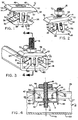
- the connector assembly is shown generally at 10 and is an assembly of an interior part or head 12 and an exterior part or head 14.
- the purpose of the connector is to secure firmly a threaded rod 16 seen in Figures 2 and 3 to the strut 18 seen in Figure 3.
- the strut 18 is channel-shape or U-shape and includes a back 20, parallel legs 21 and 22 extending from the back, with the legs being inturned or curved in the open fold or roll seen at 24 and 25, respectively, each terminating in inturned edges seen at 26 and 27, respectively.
- the legs are thus in the form of continuous inturned hooks.
- the struts may be several meters long and may be used in a wide variety of construction arrangements.
- the struts normally support a wide variety of utilities with various types of fasteners which fit within the more narrow open side of the strut formed by the inturned legs.
- the inner part or head 12 includes a central plate 30 with an extruded central hole 31 having internal rolled threads 32.
- the internal threads 32 in the hole 31 match the external threads 33 on the threaded rod 16.
- the central plate 30 of the interior head or part 12 is generally rectangular and is designed to span beneath the leg edges 26 and 27.
- the parallel end edges of the plate 30 are upturned as indicated at 35 and 36 to fit beneath and engage the strut leg edges.
- the bottom head also includes transverse or lateral flanges seen at 38 and 39, each of which includes symmetrical sloping edges 40 and 41.
- flange extension As seen at 42 and 43, for the lateral flanges 38 and 39, respectively.
- the flange extensions are each provided with a press-out forming a pintle indicated at 45 and 46, respectively.
- the press-outs are symmetrical, and each includes a sloping outer surface 47.
- the upturned edges 35 and 36 together with the flanges 38 and 39 and the sloping symmetrical surfaces thereof provide an extremely rigid and string interior part or head.
- the outer or exterior part or head 14 is also significantly rigid and includes a central rectangular plate 48 which is provided with an elongated central slot 49 which extends transversely of the strut but lengthwise of the plate.
- the plate is designed rigidly to span the exterior of the strut between the exterior of the legs.
- the exterior port is provided with sloping stiffening flanges 52 and 53 at each end which terminate in downturned relatively short flange edges seen at 54 and 55.
- the longer side of the rectangle is closed by sloping flanges 57 and 58 which terminate in downwardly extending edges or skirts 59 and 60.
- These skirts form stiffening flanges extending transversely of the strut, and each includes a flange extension seen at 62 and 63 which include slots 63 and 64, respectively, which are slightly wider than the press-out or pintles 45 and 46.
- the flange extensions 62 and 63 are designed to telescope over the flange extensions 42 and 43 of the inner head, and the wedge surfaces 47 cause such extensions to separate slightly enabling the press-out or pintle to snap into the respective slot of the exterior head. In this manner, the two parts are then assembled as in Figures 1-4.
- edges of the skirts 59 and 60 of the exterior part are provided with concave seats seen at 66 and 67 seen in Figures 2 and 3 on each side. These surfaces are designed to mate with and engage the interior or inner part of the exterior curvature of the legs of the strut seating and centering the assembly therebetween. It is noted also that the symmetrical angular edges 40 and 41 of the interior part or head also are designed to engage the interior edges of the strut legs so that the interior part is automatically piloted and centered between the legs when clamping pressure is applied.
- the parts when snapped together as in Figure 1, form the connector assembly 10.
- the exterior part may then move with respect to the interior part to the extent of the slot in the flange extensions on the exterior part.
- the exterior part may also pivot with respect to the interior part.
- a lock nut shown at 70 is threaded on the rod allowing some room to the end of the rod.
- the rod 16 with the lock nut thereon is then inserted through slot 49 and threaded into the hole 31 securing the inner part or head to the rod.
- the end of the threaded rod may be blocked against turning with respect to the inner part 12 by a suitable thread deformation, for example.
- This assembly becomes a connector system and may be sold as such.
- the lock nut 70 As the lock nut 70 is tightened, the parts move together, and the piloting or seating edges 40 and 41 of the inner part center the inner part between the inturned strut leg edges.
- the pilot seats 66 and 67 of the outer part or head also ensure that the outer pert is centered between the exterior of the legs.
- the tightening of the lock nut 70 locks the assembly in place with the rod projecting from the assembly as shown.
- the assembly Before the final tightening of the assembly, the assembly may be positioned anywhere along the strut and is easily slid along the strut to the desired location.
- the rod itself may be adjusted axially. As illustrated in Figure 4, the bottom of the strut may be provided with a series of holes indicated at 72. Accordingly, the threaded rod may be adjusted to extend through such holes, or it may be adjusted to abut against the bottom wall of the strut as seen in Figure 8.
- the lock nut may be partially closed or tightened and the assembly moved along the strut before being finally tightened in the desired location.
- connection can be made without inserting separate parts into the interior of the channel, and the assembly does not require to be threaded in from the end of the strut.
- the relative pivoting movement of the exterior part with respect to the interior part and the rod enables the assembly to be inserted quickly through the restricted opening of the strut and adjusted and quickly locked in place.
- the flanges or seats on the two heads ensure that the two heads properly seat on and grip the inturned edges of the strut legs and the external turned portion of the legs. When clamped, a substantial loading of the rod with respect to the strut is obtainable in either axial direction of the rod.
Landscapes
- Engineering & Computer Science (AREA)
- General Engineering & Computer Science (AREA)
- Mechanical Engineering (AREA)
- Mutual Connection Of Rods And Tubes (AREA)
Abstract
Description
Claims (19)
- A rod connector for a U-shape strut having legs with inturned edges including an internal head, a projecting rod secured to said head, the internal head being shaped to seat and center on the inturned edges internally of the strut, an external head relatively movable with respect to the internal head through which the rod extends and from which it projects, said external head being shaped to seat and center externally on the turned portion of the legs, and means to clamp the two heads together generally parallel to each other gripping the external turned portion and the inturned edges of the legs of the strut therebetween while supporting and connecting the rod to the strut.
- A rod connector as set forth in claim 1 wherein said internal head includes a threaded hole, said rod being threaded in and secured to said hole.
- A rod connector as set forth in claim 2 wherein said internal and external heads are formed of sheet metal plates.
- A rod connector as set forth in claim 3 wherein said threaded hole is extruded and provided with rolled internal threads matching those of the rod.
- A rod connector as set forth in claim 1 wherein said internal head and said external head are connected to each other for limited relative pivoting movement when unclamped.
- A rod connector as set forth in claim 1 wherein said internal and external heads are connected to each other for limited relative separating and closing movement.
- A rod connector as set forth in claim 1 wherein said internal head and said external head are connected to each other for both limited relative pivoting movement when unclamped and for limited relative separating and closing movement.
- A rod connector as set forth in claim 5 including a slot in said external head through which said threaded rod projects accommodating said external head for limited pivoting movement with respect to said rod and internal head.
- A rod connector as set forth in claim 5 wherein said internal and external heads are formed of sheet metal plates, which include flanges for strength, each including flange extensions forming the connection between the two heads.
- A rod connector as set forth in claim 9 wherein the flange extensions of one head include parallel slots, while the other includes snap-in pintle.
- A rod connector as set forth in claim 9 wherein said flanges include shaped edges for centering the heads with respect to the strut.
- A rod connector as set forth in claim 2 including a lock nut threaded on said rod adapted to bear against the external head when tightened.
- A rod connector as, set forth in claim 12 including means responsive to limited loosening of said nut to adjust the connector along the strut or to insert or remove the connector with respect to the strut.
- A rod connector as set forth in claim 1 including a threaded rod threaded into said internal head, and a lock nut on said threaded rod operative to clamp the two heads together when the internal head is inserted in the strut.
- A rod connector as set forth in claim 1 including in combination the strut against which the connector is clamped to achieve rod loading in either axial direction of the rod.
- A method of securing a threaded rod to a strut having inturned legs and a restricted opening, assembling an inner and outer part to each other, while permitting limited relative tilting and separation, securing the parts to the rod, tilting the rod and inner part to insert the inner part into the restricted opening of the strut, the limited tilting of the outer part providing clearance for the insertion of the inner part, and then clamping the parts together with the strut legs therebetween to clamp the rod to the strut.
- A method as set forth in claim 16 including the step of providing the outer part with a slot, permitting yet limiting the tilting of the outer part with respect to the threaded rod.
- A method as set forth in claim 17 including the step of utilizing a lock nut on the threaded rod to lock the parts together.
- A method as set forth in claim 18 including the step of providing both parts with centering seats to center the parts on the strut legs as they are clamped.
Applications Claiming Priority (2)
| Application Number | Priority Date | Filing Date | Title |
|---|---|---|---|
| US8208798P | 1998-04-17 | 1998-04-17 | |
| US82087P | 1998-04-17 |
Publications (2)
| Publication Number | Publication Date |
|---|---|
| EP0950821A1 true EP0950821A1 (en) | 1999-10-20 |
| EP0950821B1 EP0950821B1 (en) | 2007-01-10 |
Family
ID=22168989
Family Applications (1)
| Application Number | Title | Priority Date | Filing Date |
|---|---|---|---|
| EP99107596A Expired - Lifetime EP0950821B1 (en) | 1998-04-17 | 1999-04-16 | Threaded rod and strut connector and method |
Country Status (3)
| Country | Link |
|---|---|
| US (1) | US6290426B1 (en) |
| EP (1) | EP0950821B1 (en) |
| DE (1) | DE69934733T2 (en) |
Cited By (7)
| Publication number | Priority date | Publication date | Assignee | Title |
|---|---|---|---|---|
| EP1026415A3 (en) * | 1999-02-03 | 2002-01-02 | Mefa Befestigungs- und Montagesysteme GmbH | Fastening device |
| DE10128216A1 (en) * | 2001-06-11 | 2003-04-30 | Erico Products Ag Murten | Hammerhead mounting system comprises rectangular nut with inverted V-shaped cross-section on bolt, arms of V fitting into slots on washer and nut being inserted into profile and turned through right angle |
| WO2005059380A1 (en) * | 2003-12-17 | 2005-06-30 | A. Raymond & Cie | Device for connecting a support element to an add-on piece |
| WO2010013896A3 (en) * | 2008-07-28 | 2010-03-25 | Kim Dai Sik | Mounting angle-adjustable hanger for supporting piping |
| WO2014206526A1 (en) * | 2013-06-27 | 2014-12-31 | Fischerwerke Gmbh & Co. Kg | Fastener, fastening system and method for mounting a fastener to a mounting rail |
| US20210190122A1 (en) * | 2019-12-18 | 2021-06-24 | Rhino Rack Australia Pty Limited | Channel Fastener |
| CN116608197A (en) * | 2023-06-16 | 2023-08-18 | 宁波东南高强度紧固件有限公司 | Mechanical engagement high-strength bolt assembly |
Families Citing this family (45)
| Publication number | Priority date | Publication date | Assignee | Title |
|---|---|---|---|---|
| US6485221B1 (en) * | 2000-06-19 | 2002-11-26 | Canfield Industries, Inc. | Universal clamp for modular display system |
| US6712568B2 (en) | 2000-10-25 | 2004-03-30 | Nissan Technical Center North America, Inc. | Tie-down system with deformation region |
| US6846140B2 (en) * | 2000-10-25 | 2005-01-25 | Nissan Design America, Inc. | Flexible truck bed tie-down system |
| US6679640B2 (en) * | 2001-01-08 | 2004-01-20 | Vutek, Incorporated | Printing system web guide coupling assembly |
| US6749359B1 (en) * | 2001-04-27 | 2004-06-15 | Automated Fire Control, Incorporated | Seismic suspension system |
| US6511028B1 (en) * | 2001-11-23 | 2003-01-28 | Arlington Industries, Inc. | One-piece connector for elongated object holder |
| US6964540B1 (en) * | 2002-09-30 | 2005-11-15 | Foxwell Robert D | Variably adjustable watercraft ramp |
| DE10256861A1 (en) * | 2002-12-05 | 2004-06-24 | Hilti Ag | fastening system |
| US7175377B2 (en) * | 2003-01-03 | 2007-02-13 | Nissan Technical Center North America, Inc. | Track slot fastener |
| US6827531B2 (en) * | 2003-01-03 | 2004-12-07 | Nissan Technical Center North America, Inc. | Track slot fastener |
| US7497651B2 (en) * | 2003-04-16 | 2009-03-03 | Sportrack Llc | Securement mechanism |
| US7318302B2 (en) * | 2003-07-10 | 2008-01-15 | Opperman Investments, Ltd. | Equipment support for a metal building |
| US7926213B1 (en) * | 2007-04-13 | 2011-04-19 | Daktronics, Inc. | Electronic sign having slotted frame cabinets |
| US8702048B2 (en) * | 2008-05-23 | 2014-04-22 | Daktronics, Inc. | Support assembly |
| US7241094B1 (en) * | 2004-01-22 | 2007-07-10 | Epic Metals Corporation | Restraint clip |
| US20050274757A1 (en) * | 2004-05-27 | 2005-12-15 | Arend John M | Vehicular rail mounting system |
| NL1026797C2 (en) * | 2004-08-06 | 2006-02-07 | Walraven J Van Bv | Mounting assembly. |
| NL1029499C2 (en) * | 2005-07-12 | 2007-01-15 | Walraven Holding Bv J Van | Mounting assembly. |
| US20070116536A1 (en) * | 2005-11-10 | 2007-05-24 | Bleicher Kenneth A | Method and apparatus for converting cargo rings into six degree of restraint attachments |
| US7874774B2 (en) * | 2007-09-20 | 2011-01-25 | Nissan North America, Inc. | Vehicle cargo arrangement |
| US20090178723A1 (en) * | 2008-01-11 | 2009-07-16 | Joseph Cioffi | Supportive apparatus for piping and similar structures and method for the use thereof |
| US8573414B2 (en) * | 2008-04-09 | 2013-11-05 | Eye Designs, Llc | Eyewear display system |
| US8585000B2 (en) | 2008-05-22 | 2013-11-19 | Mainstream Energy Corporation | Universal end clamp |
| DE102009000736A1 (en) * | 2009-02-10 | 2010-08-19 | Hilti Aktiengesellschaft | Fastening device for arranging a rod element on a mounting rail |
| GB2472654A (en) * | 2009-08-15 | 2011-02-16 | Bentley Motors Ltd | A retention system |
| JP5295990B2 (en) * | 2010-02-10 | 2013-09-18 | 株式会社ニフコ | Fastener |
| RU2622585C2 (en) * | 2012-03-30 | 2017-06-16 | Бомбардье Рекриэйшенел Продактс Инк. | Systems and methods for fixing accessories of vehicles |
| DE102012209267A1 (en) * | 2012-06-01 | 2013-12-05 | Hilti Aktiengesellschaft | mounting arrangement |
| US9828073B1 (en) | 2012-07-30 | 2017-11-28 | Luther Cifers, III | Accessory mounting track |
| US11953146B1 (en) | 2012-07-30 | 2024-04-09 | Yakattack Llc | Accessory mount extension arm |
| DE102012218762A1 (en) * | 2012-09-06 | 2014-03-06 | Burg Silvergreen Gmbh | DEVICE FOR SECURING LOADEGUT |
| AU2013205542A1 (en) * | 2012-09-13 | 2014-03-27 | Eye Designs, Llc | Eyewear display system |
| US8844888B1 (en) * | 2012-09-19 | 2014-09-30 | Arlington Industries, Inc. | Strut clip |
| JP2016526134A (en) * | 2013-05-28 | 2016-09-01 | ジョンソン コントロールズ テクノロジー カンパニーJohnson Controls Technology Company | Fasteners, assemblies and methods |
| USD911829S1 (en) | 2013-07-30 | 2021-03-02 | Luther Cifers, III | Accessory mounting track |
| ES2862138T3 (en) | 2014-10-22 | 2021-10-07 | Erico Int Corp | Brace assembly and fixing element to stiffen a suspension bar |
| TWI675983B (en) * | 2017-03-20 | 2019-11-01 | 尚稚程 | High-strength stent combination structure |
| US11655841B2 (en) * | 2018-07-19 | 2023-05-23 | Mag Daddy Llc | Structural fastener |
| US10520113B1 (en) * | 2018-08-17 | 2019-12-31 | William J. Thompson | Threaded rod locking and ratcheting device and method of making |
| CN113454347B (en) * | 2019-02-21 | 2023-12-22 | J·范瓦尔拉芬私人控股有限公司 | Channel fasteners with torque inducing elements |
| US11725686B1 (en) * | 2019-08-13 | 2023-08-15 | Yakattack, Llc | Rotation locking device for T-bolt |
| JP6964694B2 (en) * | 2020-01-10 | 2021-11-10 | 因幡電機産業株式会社 | Fixture |
| US11187353B1 (en) | 2021-04-29 | 2021-11-30 | Vibration Mountings & Controls, Inc. | Strut channel mounting clip |
| US12241584B2 (en) * | 2021-06-17 | 2025-03-04 | Terra Three Industries, LLC | Self-suspending lock with wings and system |
| USD1083694S1 (en) * | 2023-10-31 | 2025-07-15 | Unistrut International Corporation | Strut nut assembly |
Citations (4)
| Publication number | Priority date | Publication date | Assignee | Title |
|---|---|---|---|---|
| DE1950662U (en) * | 1966-04-29 | 1966-12-01 | Kleinhuis Fa H | RAIL, IN PARTICULAR PROFILE RAIL. |
| US4783040A (en) | 1985-06-10 | 1988-11-08 | Aickin Development Corporation | Non-metallic strut system |
| US5375798A (en) * | 1992-07-06 | 1994-12-27 | Hungerford, Jr.; Charles S. | Connector for facilitating a connection between a channel member and a support member |
| EP0805297A2 (en) * | 1996-05-03 | 1997-11-05 | Diag Design Ag | Anchor device |
Family Cites Families (10)
| Publication number | Priority date | Publication date | Assignee | Title |
|---|---|---|---|---|
| DE805297C (en) * | 1949-11-12 | 1951-05-15 | Wilhelm Stoehr | Snap-together seat |
| US2767609A (en) * | 1952-06-24 | 1956-10-23 | Ex Corp | Spring urged nut having outwardly projecting teeth thereon |
| NL6603194A (en) * | 1965-04-09 | 1966-10-10 | ||
| US4460299A (en) * | 1981-12-14 | 1984-07-17 | B-Line Systems, Inc. | Fastener |
| US4784552A (en) * | 1982-02-01 | 1988-11-15 | Unistrut International Corp. | Nuts for channeled structural members |
| US4575295A (en) * | 1984-01-11 | 1986-03-11 | Gte Products Corporation | Fastener for channeled structural members |
| US4830531A (en) * | 1985-10-04 | 1989-05-16 | Unistrut International Corp. | Unitary connection assembly for metal channels and method for assembly |
| US4950099A (en) * | 1988-12-20 | 1990-08-21 | Swiss Aluminum Ltd. | Releasable clamping-type compressive joint |
| SE501478C2 (en) * | 1992-11-04 | 1995-02-27 | Josef Chudoba | Spring Nut device |
| DE4243185A1 (en) * | 1992-12-19 | 1994-06-23 | Hilti Ag | Fastening device |
-
1999
- 1999-04-16 EP EP99107596A patent/EP0950821B1/en not_active Expired - Lifetime
- 1999-04-16 DE DE69934733T patent/DE69934733T2/en not_active Expired - Fee Related
- 1999-04-16 US US09/293,922 patent/US6290426B1/en not_active Expired - Fee Related
Patent Citations (4)
| Publication number | Priority date | Publication date | Assignee | Title |
|---|---|---|---|---|
| DE1950662U (en) * | 1966-04-29 | 1966-12-01 | Kleinhuis Fa H | RAIL, IN PARTICULAR PROFILE RAIL. |
| US4783040A (en) | 1985-06-10 | 1988-11-08 | Aickin Development Corporation | Non-metallic strut system |
| US5375798A (en) * | 1992-07-06 | 1994-12-27 | Hungerford, Jr.; Charles S. | Connector for facilitating a connection between a channel member and a support member |
| EP0805297A2 (en) * | 1996-05-03 | 1997-11-05 | Diag Design Ag | Anchor device |
Cited By (12)
| Publication number | Priority date | Publication date | Assignee | Title |
|---|---|---|---|---|
| EP1026415A3 (en) * | 1999-02-03 | 2002-01-02 | Mefa Befestigungs- und Montagesysteme GmbH | Fastening device |
| DE10128216A1 (en) * | 2001-06-11 | 2003-04-30 | Erico Products Ag Murten | Hammerhead mounting system comprises rectangular nut with inverted V-shaped cross-section on bolt, arms of V fitting into slots on washer and nut being inserted into profile and turned through right angle |
| WO2005059380A1 (en) * | 2003-12-17 | 2005-06-30 | A. Raymond & Cie | Device for connecting a support element to an add-on piece |
| KR100789326B1 (en) * | 2003-12-17 | 2007-12-28 | 아. 레이몽 에 씨에 | Device for connecting a support element to an add-on piece |
| RU2358165C2 (en) * | 2003-12-17 | 2009-06-10 | А. Раймон Энд Сие | Device for joining support or bearing item with other item to be fixed to it |
| US7568868B2 (en) | 2003-12-17 | 2009-08-04 | A. Raymond Et Cie | Device for connecting a support element to an add-on piece |
| WO2010013896A3 (en) * | 2008-07-28 | 2010-03-25 | Kim Dai Sik | Mounting angle-adjustable hanger for supporting piping |
| WO2014206526A1 (en) * | 2013-06-27 | 2014-12-31 | Fischerwerke Gmbh & Co. Kg | Fastener, fastening system and method for mounting a fastener to a mounting rail |
| DE102013113735A1 (en) | 2013-06-27 | 2014-12-31 | Fischerwerke Gmbh & Co. Kg | Fastener, fastening system and method for mounting a fastener to a mounting rail |
| US20210190122A1 (en) * | 2019-12-18 | 2021-06-24 | Rhino Rack Australia Pty Limited | Channel Fastener |
| CN116608197A (en) * | 2023-06-16 | 2023-08-18 | 宁波东南高强度紧固件有限公司 | Mechanical engagement high-strength bolt assembly |
| CN116608197B (en) * | 2023-06-16 | 2024-03-22 | 宁波东南高强度紧固件有限公司 | Mechanical engagement high-strength bolt assembly |
Also Published As
| Publication number | Publication date |
|---|---|
| EP0950821B1 (en) | 2007-01-10 |
| DE69934733T2 (en) | 2007-05-24 |
| DE69934733D1 (en) | 2007-02-22 |
| US6290426B1 (en) | 2001-09-18 |
Similar Documents
| Publication | Publication Date | Title |
|---|---|---|
| US6290426B1 (en) | Threaded rod and strut connector and method | |
| US12049759B2 (en) | Linear surface covering system | |
| CA2906388C (en) | Channel framing with additional functional side and fittings therefor | |
| US9580900B2 (en) | Fitting for channel framing | |
| US5704571A (en) | Cable tray and method of installation | |
| US20210404504A1 (en) | Structural Fastener | |
| AU2014204518B2 (en) | Folded beam clamp | |
| CN111609018A (en) | Structural fastener | |
| US20050173363A1 (en) | Mounting fastening | |
| US11655841B2 (en) | Structural fastener | |
| EP3983709B1 (en) | An assembly for bracing suspended non-structural building components | |
| JPH062008Y2 (en) | Supporting bracket for hanging rod members | |
| CN219975804U (en) | Fixing support | |
| JPH0519670Y2 (en) | ||
| GB2585157A (en) | Fitting for channel framing | |
| GB2295193A (en) | A clamp that allows the downward orientation of an opening in a support | |
| JPH0728280U (en) | Pipe support bracket | |
| EP1500858A1 (en) | Clamp for hanging pipes | |
| JPH0673831A (en) | Joint device of ceiling bar |
Legal Events
| Date | Code | Title | Description |
|---|---|---|---|
| PUAI | Public reference made under article 153(3) epc to a published international application that has entered the european phase |
Free format text: ORIGINAL CODE: 0009012 |
|
| AK | Designated contracting states |
Kind code of ref document: A1 Designated state(s): AT CH DE ES FR GB IT LI NL SE |
|
| AX | Request for extension of the european patent |
Free format text: AL;LT;LV;MK;RO;SI |
|
| 17P | Request for examination filed |
Effective date: 20000120 |
|
| AKX | Designation fees paid |
Free format text: AT CH DE ES FR GB IT LI NL SE |
|
| 17Q | First examination report despatched |
Effective date: 20030709 |
|
| GRAP | Despatch of communication of intention to grant a patent |
Free format text: ORIGINAL CODE: EPIDOSNIGR1 |
|
| GRAS | Grant fee paid |
Free format text: ORIGINAL CODE: EPIDOSNIGR3 |
|
| GRAA | (expected) grant |
Free format text: ORIGINAL CODE: 0009210 |
|
| AK | Designated contracting states |
Kind code of ref document: B1 Designated state(s): AT CH DE ES FR GB IT LI NL SE |
|
| PG25 | Lapsed in a contracting state [announced via postgrant information from national office to epo] |
Ref country code: LI Free format text: LAPSE BECAUSE OF FAILURE TO SUBMIT A TRANSLATION OF THE DESCRIPTION OR TO PAY THE FEE WITHIN THE PRESCRIBED TIME-LIMIT Effective date: 20070110 Ref country code: CH Free format text: LAPSE BECAUSE OF FAILURE TO SUBMIT A TRANSLATION OF THE DESCRIPTION OR TO PAY THE FEE WITHIN THE PRESCRIBED TIME-LIMIT Effective date: 20070110 Ref country code: AT Free format text: LAPSE BECAUSE OF FAILURE TO SUBMIT A TRANSLATION OF THE DESCRIPTION OR TO PAY THE FEE WITHIN THE PRESCRIBED TIME-LIMIT Effective date: 20070110 |
|
| REG | Reference to a national code |
Ref country code: GB Ref legal event code: FG4D |
|
| REF | Corresponds to: |
Ref document number: 69934733 Country of ref document: DE Date of ref document: 20070222 Kind code of ref document: P |
|
| PGFP | Annual fee paid to national office [announced via postgrant information from national office to epo] |
Ref country code: NL Payment date: 20070315 Year of fee payment: 9 Ref country code: GB Payment date: 20070315 Year of fee payment: 9 |
|
| PGFP | Annual fee paid to national office [announced via postgrant information from national office to epo] |
Ref country code: DE Payment date: 20070326 Year of fee payment: 9 |
|
| PG25 | Lapsed in a contracting state [announced via postgrant information from national office to epo] |
Ref country code: SE Free format text: LAPSE BECAUSE OF FAILURE TO SUBMIT A TRANSLATION OF THE DESCRIPTION OR TO PAY THE FEE WITHIN THE PRESCRIBED TIME-LIMIT Effective date: 20070410 |
|
| PG25 | Lapsed in a contracting state [announced via postgrant information from national office to epo] |
Ref country code: ES Free format text: LAPSE BECAUSE OF FAILURE TO SUBMIT A TRANSLATION OF THE DESCRIPTION OR TO PAY THE FEE WITHIN THE PRESCRIBED TIME-LIMIT Effective date: 20070421 |
|
| ET | Fr: translation filed | ||
| REG | Reference to a national code |
Ref country code: CH Ref legal event code: PL |
|
| PLBE | No opposition filed within time limit |
Free format text: ORIGINAL CODE: 0009261 |
|
| STAA | Information on the status of an ep patent application or granted ep patent |
Free format text: STATUS: NO OPPOSITION FILED WITHIN TIME LIMIT |
|
| 26N | No opposition filed |
Effective date: 20071011 |
|
| PG25 | Lapsed in a contracting state [announced via postgrant information from national office to epo] |
Ref country code: IT Free format text: LAPSE BECAUSE OF FAILURE TO SUBMIT A TRANSLATION OF THE DESCRIPTION OR TO PAY THE FEE WITHIN THE PRESCRIBED TIME-LIMIT Effective date: 20070110 |
|
| PGFP | Annual fee paid to national office [announced via postgrant information from national office to epo] |
Ref country code: FR Payment date: 20070312 Year of fee payment: 9 |
|
| GBPC | Gb: european patent ceased through non-payment of renewal fee |
Effective date: 20080416 |
|
| NLV4 | Nl: lapsed or anulled due to non-payment of the annual fee |
Effective date: 20081101 |
|
| PG25 | Lapsed in a contracting state [announced via postgrant information from national office to epo] |
Ref country code: NL Free format text: LAPSE BECAUSE OF NON-PAYMENT OF DUE FEES Effective date: 20081101 Ref country code: DE Free format text: LAPSE BECAUSE OF NON-PAYMENT OF DUE FEES Effective date: 20081101 |
|
| REG | Reference to a national code |
Ref country code: FR Ref legal event code: ST Effective date: 20081231 |
|
| PG25 | Lapsed in a contracting state [announced via postgrant information from national office to epo] |
Ref country code: FR Free format text: LAPSE BECAUSE OF NON-PAYMENT OF DUE FEES Effective date: 20080430 |
|
| PG25 | Lapsed in a contracting state [announced via postgrant information from national office to epo] |
Ref country code: GB Free format text: LAPSE BECAUSE OF NON-PAYMENT OF DUE FEES Effective date: 20080416 |