EP0950794B1 - Dispositif et procédé pour l'équipement de puits souterrain - Google Patents
Dispositif et procédé pour l'équipement de puits souterrain Download PDFInfo
- Publication number
- EP0950794B1 EP0950794B1 EP19990302894 EP99302894A EP0950794B1 EP 0950794 B1 EP0950794 B1 EP 0950794B1 EP 19990302894 EP19990302894 EP 19990302894 EP 99302894 A EP99302894 A EP 99302894A EP 0950794 B1 EP0950794 B1 EP 0950794B1
- Authority
- EP
- European Patent Office
- Prior art keywords
- wellbore
- packer
- annulus
- flow
- assembly
- Prior art date
- Legal status (The legal status is an assumption and is not a legal conclusion. Google has not performed a legal analysis and makes no representation as to the accuracy of the status listed.)
- Expired - Lifetime
Links
- 238000000034 method Methods 0.000 title claims description 44
- 239000012530 fluid Substances 0.000 claims description 146
- 238000012856 packing Methods 0.000 claims description 81
- 238000012360 testing method Methods 0.000 claims description 74
- 238000004891 communication Methods 0.000 claims description 52
- 230000015572 biosynthetic process Effects 0.000 claims description 37
- 238000005755 formation reaction Methods 0.000 description 34
- 239000012065 filter cake Substances 0.000 description 28
- 238000006073 displacement reaction Methods 0.000 description 16
- 239000002002 slurry Substances 0.000 description 10
- 239000000463 material Substances 0.000 description 3
- 239000004576 sand Substances 0.000 description 2
- 238000007789 sealing Methods 0.000 description 2
- 230000006641 stabilisation Effects 0.000 description 2
- 238000011105 stabilization Methods 0.000 description 2
- 230000000087 stabilizing effect Effects 0.000 description 2
- 238000007792 addition Methods 0.000 description 1
- 230000000712 assembly Effects 0.000 description 1
- 238000000429 assembly Methods 0.000 description 1
- 239000004568 cement Substances 0.000 description 1
- 238000012217 deletion Methods 0.000 description 1
- 230000037430 deletion Effects 0.000 description 1
- 230000002706 hydrostatic effect Effects 0.000 description 1
- 238000012986 modification Methods 0.000 description 1
- 230000004048 modification Effects 0.000 description 1
- 239000011236 particulate material Substances 0.000 description 1
- 230000001681 protective effect Effects 0.000 description 1
- 230000001105 regulatory effect Effects 0.000 description 1
- 238000010008 shearing Methods 0.000 description 1
- 230000000638 stimulation Effects 0.000 description 1
- 238000006467 substitution reaction Methods 0.000 description 1
- 238000005406 washing Methods 0.000 description 1
Images


Classifications
-
- E—FIXED CONSTRUCTIONS
- E21—EARTH DRILLING; MINING
- E21B—EARTH DRILLING, e.g. DEEP DRILLING; OBTAINING OIL, GAS, WATER, SOLUBLE OR MELTABLE MATERIALS OR A SLURRY OF MINERALS FROM WELLS
- E21B47/00—Survey of boreholes or wells
- E21B47/10—Locating fluid leaks, intrusions or movements
- E21B47/117—Detecting leaks, e.g. from tubing, by pressure testing
-
- E—FIXED CONSTRUCTIONS
- E21—EARTH DRILLING; MINING
- E21B—EARTH DRILLING, e.g. DEEP DRILLING; OBTAINING OIL, GAS, WATER, SOLUBLE OR MELTABLE MATERIALS OR A SLURRY OF MINERALS FROM WELLS
- E21B34/00—Valve arrangements for boreholes or wells
- E21B34/06—Valve arrangements for boreholes or wells in wells
-
- E—FIXED CONSTRUCTIONS
- E21—EARTH DRILLING; MINING
- E21B—EARTH DRILLING, e.g. DEEP DRILLING; OBTAINING OIL, GAS, WATER, SOLUBLE OR MELTABLE MATERIALS OR A SLURRY OF MINERALS FROM WELLS
- E21B43/00—Methods or apparatus for obtaining oil, gas, water, soluble or meltable materials or a slurry of minerals from wells
- E21B43/02—Subsoil filtering
- E21B43/10—Setting of casings, screens, liners or the like in wells
-
- Y—GENERAL TAGGING OF NEW TECHNOLOGICAL DEVELOPMENTS; GENERAL TAGGING OF CROSS-SECTIONAL TECHNOLOGIES SPANNING OVER SEVERAL SECTIONS OF THE IPC; TECHNICAL SUBJECTS COVERED BY FORMER USPC CROSS-REFERENCE ART COLLECTIONS [XRACs] AND DIGESTS
- Y10—TECHNICAL SUBJECTS COVERED BY FORMER USPC
- Y10T—TECHNICAL SUBJECTS COVERED BY FORMER US CLASSIFICATION
- Y10T137/00—Fluid handling
- Y10T137/1624—Destructible or deformable element controlled
- Y10T137/1632—Destructible element
- Y10T137/1669—Tensile or sheer pin or bolt
Definitions
- the present invention relates generally to operations performed in conjunction with subterranean wells and more particularly provides methods and apparatus useful in gravel packing operations.
- a horizontal or highly deviated portion of a wellbore is completed without being lined with protective casing and cement.
- a completion operation known as gravel packing.
- sand or other particulate material is flowed into an annular space formed radially between the wellbore and one or more screens attached to a special purpose packer set in the wellbore. The sand and screens act to prevent the formation from breaking up and flowing to the earth's surface along with the fluids produced from the formation.
- a "filter cake” is applied to the walls of the wellbore to aid in stabilizing the formation intersected by the wellbore.
- the filter cake temporarily prevents breaking up of the formation or, ultimately, collapse of the formation during completion operations.
- the filter cake may be a gelatinous material spotted across the uncased wellbore, or it may be material conveyed to the uncased wellbore by mud circulation, etc.
- the filter cake In order for the filter cake to provide maximum stabilization of the formation it is generally desirable for positive pressure to be applied from the wellbore to the formation. That is, fluid pressure in the wellbore should exceed fluid pressure in the formation by a desired amount. This positive pressure acts, in essence, to press the filter cake against the formation. Thus, although the filter cake is not generally pressure-tight, if a positive pressure is continuously applied to the filter cake, the filter cake will provide adequate support to prevent damage to the formation.
- New completion techniques applied to a deepwater Gulf of Mexico tension leg platform for successfully gravel packing an openhole horizontal interval of 730 meter (2400 feet) were described in a paper by Duhon et al. published in the OTC proceedings, OTC-8586.
- To install the screen and pump the gravel pack the screen and gravel pack packer are run into the horizontal hole and the packer is set.
- An actuated reverse ball seat is used to maintain hydrostatic overbalance on the formation during all phases of the completion.
- a method of completing a subterranean well in which continuous fluid communication is established with a portion of a wellbore intersecting a formation.
- Associated apparatus is also provided.
- a gravel packing operation is performed in which a tubular string is attached to a gravel packing assembly including a packer, a screen and a packer testing device.
- fluid is circulated through the tubular string, thereby "washing in” the gravel packing assembly and maintaining positive pressure on a filter cake lining an uncased portion of the wellbore.
- the packer is set in the well and then pressure tested to verify that is has properly set.
- the testing operation is accomplished by applying fluid pressure to an annulus between the tubular string and the wellbore, while maintaining positive fluid pressure on the filter cake via the tubular string.
- the wellbore is gravel packed by flowing a gravel slurry through the tubular string to an annulus between the screen and the uncased wellbore. In this manner, positive pressure is continuously applied to the filter cake, thereby preventing damage to the formation intersected by the wellbore.
- an apparatus which establishes continuous fluid communication with a portion of a wellbore during completion operations.
- the described embodiment of the apparatus includes a packer testing device. The device permits fluid communication between the tubular string and the wellbore portion during pressure testing of a packer interconnected with the apparatus.
- a method of completing a subterranean well having a wellbore intersecting a formation comprising the steps of: conveying an assembly into the wellbore, the assembly including a packer, a tubular string engaged with the packer, a screen and a flow directing mechanism, the flow directing mechanism permitting fluid flow longitudinally through the assembly during conveyance into the wellbore; setting the packer in the wellbore, thereby dividing a first annulus from a second annulus, the first and second annulus being formed between the assembly and the wellbore, the tubular string being positioned within the first annulus and the screen being positioned within the second annulus; actuating the flow directing mechanism to isolate the first annulus from the second annulus while permitting fluid communication between the interior of the tubular string and the second annulus; and actuating the flow directing mechanism to permit fluid communication between the second annulus and the first annulus.
- the step of actuating the flow directing mechanism to isolate the first annulus further comprises displacing the tubular string after the step of setting the packer.
- the step of actuating the flow directing mechanism to permit fluid communication further comprises applying fluid pressure to the first annulus.
- the flow directing mechanism includes a packer testing device, and the step of actuating the flow directing mechanism to isolate the first annulus further comprises closing a valve of the packer testing device.
- the flow directing mechanism includes a packer testing device, and the step of actuating the flow directing mechanism to permit fluid communication further comprises opening a valve of the packer testing device.
- the flow directing mechanism includes a packer testing device, and the conveying step further comprises flowing the fluid through a valve of the packer testing device.
- positive pressure may be applied to an interface between the wellbore and the formation.
- the method further comprises the step of testing the packer after the setting step by applying fluid pressure to the first annulus.
- the testing step may further comprise maintaining positive fluid pressure applied to an interface between the wellbore and the formation.
- a filter cake is disposed at an interface between the wellbore and the formation.
- the method may further comprise the step of testing the packer by applying fluid pressure to the first annulus after the setting step and after the step of actuating the flow directing mechanism to isolate the first annulus, while maintaining positive fluid pressure applied to the filter cake.
- a method of completing a subterranean well comprising the steps of: conveying a gravel packing assembly into the well; the gravel packing assembly including a packer and a well screen attached to the packer; setting the packer in the wellbore, thereby dividing the wellbore into first and second portions; and testing the packer by applying fluid pressure to the first wellbore portion while simultaneously applying fluid pressure to the second wellbore portion external to the gravel packing assembly.
- a tubular string attached to the gravel packing assembly may be disposed within the first wellbore portion.
- fluid pressure may be applied to the second wellbore portion by providing fluid communication between the tubular string and the second wellbore portion.
- the gravel packing assembly further includes a packer testing device, and the testing step further comprises actuating the packer testing device to provide fluid communication between a tubular string attached to the gravel packing assembly and the second wellbore portion.
- the further comprises the step of gravel packing by flowing a slurry through a tubular string engaged with the gravel packing assembly and into the second wellbore portion external to the screen.
- the gravel packing assembly further includes a packer testing device, and in the testing step the packer testing device prevents fluid communication between the first wellbore portion external to the tubular string and the second wellbore portion external to the screen, and in the gravel packing step the packer testing device permits fluid flow from the second wellbore portion external to the screen, through the screen into the gravel packing assembly and then to the first wellbore portion external to the tubular string.
- the gravel packing assembly further includes a packer testing device, and in the testing step the packer testing device prevents fluid flow from the tubular string through the interior of the screen, and in the gravel packing step the packer testing device permits fluid flow from the second wellbore portion through the screen and then to the first wellbore portion external to the tubular string.
- the gravel packing assembly further includes a packer testing device
- the method further comprises the step of actuating the packer testing device after the testing step and before the gravel packing step.
- the actuating step may further comprise applying a predetermined fluid pressure differential to the packer testing device.
- the packer testing device may be interconnected in a first portion of the gravel packing assembly engaged with the tubular string, and the packer and screen may be interconnected in a second portion of the gravel packing assembly, and the method may further comprise the step of actuating the packer testing device after the setting step and before the testing step by displacing the first gravel packing assembly portion relative to the second gravel packing assembly portion.
- apparatus operatively positionable within a subterranean well, the apparatus comprising: a generally tubular housing having a flow passage formed therethrough; a first valve permitting fluid flow through the flow passage in a first direction but preventing fluid flow through the flow passage in a second direction opposite to the first direction; a second valve interconnected to the first valve, the second valve permitting fluid flow therethrough when a predetermined fluid pressure is applied across the first valve; and a third valve preventing fluid flow therethrough when a portion thereof is displaced relative to the housing.
- the first valve is preferably a check valve.
- the second valve preferably includes first and second members, the first member being attached to the first valve, and the first member displacing relative to the second member, thereby opening the second valve, when the predetermined fluid pressure is applied across the first valve.
- the third valve preferably includes a member releasably secured relative to the housing, the member displacing relative to the housing, thereby closing the third valve, when a predetermined force is applied to the member.
- the apparatus further comprises a structure releasably securing the member against displacement relative to the housing, the structure permitting relative displacement between the member and the housing when the predetermined force is applied to the member.
- the apparatus further comprises an engagement structure engaged with the third valve and a tubular member outwardly surrounding the housing, the tubular member having an engagement profile formed internally thereon, and the engagement structure engaging the engagement profile when the housing is displaced relative to the tubular member.
- the engagement structure may be releasably secured against displacement relative to the housing, the engagement structure and third valve portion displacing relative to the housing when the engagement structure is engaged with the engagement profile and a predetermined force is applied to the engagement structure.
- apparatus operatively positionable within a subterranean well, the apparatus comprising: a tubular housing assembly having a flow passage formed therethrough, the flow passage having first and second portions; a check valve restricting fluid flow from the first to the second flow passage portion and permitting relatively unrestricted fluid flow from the second to the first flow passage portion; and a second valve selectively permitting and preventing fluid flow from the first to the second flow passage portion in response to fluid pressure across the check valve.
- the second valve includes first and second members, the first and second members displacing relative to each other when a predetermined fluid pressure is applied across the check valve.
- One of the first and second members may be attached to a portion of the check valve.
- the check valve portion may be a seat of the check valve.
- One of the first and second members may be releasably secured against displacement relative to the housing assembly.
- the apparatus further comprises a third valve selectively permitting and preventing fluid flow from the first to the second flow passage portion in response to displacement of a portion of the third valve relative to the housing assembly.
- the third valve may include a member displacing relative to the housing assembly when a predetermined force is applied to the member.
- the member may be attached to, and displaceable with, the third valve portion.
- the third valve member may disposed at least partially external to the housing assembly, the member being interconnected to the third valve portion and displaceable therewith. The member may be releasably secured against displacement relative to the housing assembly.
- apparatus for use in completing a subterranean well, the apparatus comprising: a tubular string; and a gravel packing assembly engaged with the tubular string, the gravel packing assembly including a packer, a screen and a packer testing device, the packer testing device being selectively configurable in a first configuration in which fluid flow is permitted from the tubular string then through the gravel packing assembly internal to the screen, and a second configuration in which fluid flow from the tubular string is prevented from flowing through the gravel packing assembly internal to the screen.
- the packer testing assembly may prevent fluid communication between the exterior of the tubular string opposite the packer from the screen and the interior of the screen when the packer is set in the well.
- the packer testing device is further selectively configurable in a third configuration in which fluid flow is permitted between the exterior of the tubular string opposite the packer from the screen and the interior of the screen when the packer is set in the well.
- the third configuration of the packer testing device may be selectable in response to a predetermined fluid pressure difference between the exterior of the tubular string opposite the packer from the screen and the interior of the screen when the packer is set in the well.
- the second configuration of the packer testing device is selectable in response to displacement of the tubular string relative to a portion of the gravel packing assembly.
- apparatus operatively positionable within a subterranean wellbore opposite a formation intersected by the wellbore, the apparatus comprising: an assembly having first and second opposite ends and including a packer, a screen, and a flow directing mechanism, the flow directing mechanism permitting fluid communication longitudinally through the interior of the assembly between the first and second opposite ends when the assembly is conveyed into the wellbore, and selectively permitting and preventing fluid communication between the interior of the screen and a first annulus formed between the assembly and the wellbore and extending to the earth's surface when the packer is set in the wellbore.
- the apparatus further comprises a tubular string attached to the assembly, and the flow directing mechanism substantially continuously permits fluid communication between a second annulus formed between the screen and the wellbore when the packer is set in the wellbore and a selected one of the tubular string and the first annulus.
- FIG. 1 Representatively and schematically illustrated in FIG. 1 is a method 10 of completing a subterranean well which embodies principles of the present invention.
- directional terms such as “above”, “below”, “upper”, “lower”, etc., are used for convenience in referring to the accompanying drawings. Additionally, it is to be understood that the various embodiments of the present invention described herein may be utilized in various orientations, such as inclined, inverted, horizontal, vertical, etc., without departing from the principles of the present invention.
- a wellbore 12 of the well is depicted in FIG. 1 as being generally vertical and having both. cased and uncased portions.
- principles of the present invention may be incorporated in methods performed in wells having generally horizontal wellbores, highly deviated wellbores, wellbores with a combination of generally vertical and generally horizontal or highly deviated portions, fully cased wellbores, substantially uncased wellbores, and other types of wellbores.
- a lower portion of the wellbore 12 is depicted in FIG. 1 as having a filter cake 14 or other formation stabilizing material deposited at an interface between the wellbore 12 and a formation 16 intersected by the wellbore, but it is not necessary for the filter cake to be present in keeping with the principles of the present invention.
- the filter cake 14 is well known to those skilled in the art and is used to provide a degree of stabilization for the formation 16.
- the method 10 uniquely maintains a positive fluid pressure applied to the filter cake 14 during completion operations, thereby preventing damage to, or collapse of, the formation 16.
- fluid pressure in the wellbore 12 adjacent the filter cake 14 exceeds fluid pressure in the formation 16 during the completion operations.
- the wellbore 12 adjacent the formation 16 is gravel packed utilizing techniques similar in many respects to conventional gravel packing operations well known to those skilled in the art.
- gravel packing operations utilizing a Versa-Trieve® packer in a gravel packing assembly with a Multi-Position ToolTM service tool are well known.
- the Versa-Trieve® packer and Multi-Position ToolTM are available from Halliburton Energy Services, Inc. of Duncan, Oklahoma. The operation of these tools is well known to those skilled in the art.
- a gravel packing assembly 18 is conveyed into the wellbore 12 attached to a tubular string 20, such as a drill string, tubing string, work string, etc., and positioned generally opposite the formation 16.
- a tubular string 20 such as a drill string, tubing string, work string, etc.
- principles of the present invention may be incorporated in methods of performing other completion operations and other types of operations.
- the operation performed may be a fracturing, acidizing or other type of stimulation operation.
- the gravel packing assembly 18 includes a packer 22 and one or more well screens 24.
- the packer 22 and screen 24 are interconnected in an outer portion 26 of the gravel packing assembly 18.
- An inner portion 28 of the gravel packing assembly 18 is disposed longitudinally within the outer portion 26 and is axially displaceable relative thereto.
- the tubular string 20 is attached to the inner portion 28 and, in the embodiment shown in FIG. 1, the inner portion may be displaced relative to the outer portion 26 by manipulation of the tubular string at the earth's surface.
- other ways of displacing one portion of an assembly relative to another portion of an assembly may be utilized without departing from the principles of the present invention.
- the inner and outer portions 28, 26 of the gravel packing assembly 18 cooperate for actuation of a flow directing mechanism 30 included in the gravel packing assembly.
- the flow directing mechanism 30 controls fluid communication and fluid flow between the interior of the tubular string 20, an upper annulus 32 formed between the wellbore 12 and the tubular string 20 above the packer 22 and extending to the earth's surface, a lower annulus 34 formed between the gravel packing assembly 18 and the wellbore below the packer, and the interior of the screen 24.
- the flow directing mechanism 30 maintains the lower annulus 34 in substantially continuous fluid communication with the interior of the tubular string 20 or the upper annulus 32 during the completion operation.
- fluid pressure in the lower annulus 34 may be regulated via the tubular string 20 or the upper annulus 32 at the earth's surface, so that positive pressure is maintained on the filter cake 14.
- fluid communication between the tubular string 20 and the lower annulus 34 is maintained even during pressure testing of the packer 22 after it is set in the wellbore 12.
- the flow directing mechanism 30 includes a number of flow passages, openings, valves, etc. in the gravel packing assembly 18, as described more fully below. It is to be clearly understood, however, that the flow directing mechanism 30 could be differently constructed, positioned, etc., from that representatively illustrated in the accompanying drawings, without departing from the principles of the present invention. For example, multiple elements could be combined, integrally formed elements could be separated, elements could be differently positioned and configured, elements could be differently arranged with respect to each other, different numbers of elements could be utilized, etc.
- the flow directing mechanism 30 includes a flow passage 36 extending from the upper annulus 32 and partially through the gravel packing assembly 18 to a screen 38.
- the screen 38 is used to filter fluid flowing from another interior flow passage 40 to the flow passage 36, but fluid may also flow from the flow passage 36 to the flow passage 40 through the screen 38.
- a packer testing device 42 controls fluid flow between the flow passage 40 and another interior flow passage 44 extending from the packer testing device to the interior of the screen 24 through a tubular washpipe 46 positioned within the screen 24.
- the flow directing mechanism 30 also includes an interior flow passage 48 extending between the interior of the tubular string 20 and the interior of a crossover sub 50 of the inner portion 28.
- ports 52 formed laterally through a sidewall of the crossover sub 50 When ports 52 formed laterally through a sidewall of the crossover sub 50 are placed in fluid communication with openings 54 formed laterally through a sidewall of the outer portion 26, fluid communication is established between the interior of the tubular string 20 and the lower annulus 34, as shown in FIG. 1.
- a tapered ball seat 56 permits selective shutting off of fluid communication between the flow passage 48 and the flow passage 36 via flow passages 58 extending therebetween.
- FIG. 1 shows the gravel packing assembly 18 in a configuration in which a slurry of fluid and gravel may be flowed through the tubular string 20, through the flow passage 48, and outward into the lower annulus 34 through the ports 52 and openings 54 to deposit the gravel in the lower annulus.
- the fluid portion of the slurry is permitted to flow inwardly through the screen 24 into the flow passage 44, to the flow passage 40 through the packer testing device 42, through the screen 38 to the flow passage 36, and thence to the upper annulus 32 for return to the earth's surface.
- the packer 22 is set in the wellbore 12 to isolate the upper annulus 32 from the lower annulus 34.
- the packer 22 is depicted as being set in a cased portion of the wellbore 12, but it could be set in an uncased portion of the wellbore without departing from the principles of the present invention.
- the packer 22 After the packer 22 has been set in the wellbore 12, but before the slurry is flowed through the tubular string 20 and gravel packing assembly 18 to deposit gravel in the lower annulus 34, the packer should be tested to determine whether it has been properly set in the wellbore 12.
- the crossover 50 (and the remainder of the inner portion 28) is downwardly displaced relative to the outer portion 26 as compared to that shown in FIG. 1, so that the ports 52 are no longer in fluid communication with the openings 54, but the openings are in fluid communication with the upper annulus 32 via a flow passage 62 represented in FIG. 1 as an annular space between the inner and outer portions 28, 26.
- a ball 60 or other plugging member is installed in the gravel packing assembly 18 when the packer 22 is set and sealingly engages the seat 56 to close off fluid communication between the flow passage 48 and the flow passage 36.
- the upper annulus 32 is in fluid communication with the lower annulus 34 via the flow passage 62 and openings 54, and the tubular string 20 is not in fluid communication with the lower annulus due to the fact that the crossover 50 is downwardly displaced relative to the outer portion 26.
- positive pressure may be maintained on the filter cake 14 via the upper annulus 32.
- the packer 22 may not be pressure tested, since the upper annulus and lower annulus 34 are in fluid communication.
- the gravel packing assembly 18 includes features which permit the packer 22 to be tested, while simultaneously maintaining positive pressure on the filter cake 14.
- the packer testing device 42 includes multiple valves which control fluid communication and fluid flow between the flow passage 40 and the flow passage 44. In a manner described more fully below, the packer testing device 42 permits the upper annulus 32 to be isolated from the lower annulus 34 when the packer 22 is tested.
- the inner portion 28 is displaced upwardly relative to the outer portion 26, so that the ports 52 are in fluid communication with the openings 54 as shown in FIG. 1, thereby providing fluid communication between the flow passage 48 and the lower annulus, and to actuate the packer testing device 42 to isolate the upper annulus 32 from the lower annulus 34.
- fluid pressure may be applied to the upper annulus 32 to test the packer 22 while positive pressure is maintained on the filter cake 14 via the tubular string 20.
- the packer testing device 42 also permits fluid communication between the flow passage 40 and the flow passage 44 when the gravel packing assembly 18 is being conveyed into the wellbore 12, so that the gravel packing assembly may be "washed in” by circulating fluid from the interior of the tubular string 20, through the flow passage 48, through the flow passages 58 (the ball 60 is not present during conveyance of the gravel packing assembly into the wellbore), inward through the screen 38 to the flow passage 40, through the packer testing device 42 to the flow passage 44, and outward through a float shoe 64 or check valve at a lower end of the gravel packing assembly. From the float shoe 64, the fluid may be returned to the earth's surface by flowing upward between the gravel packing assembly 18 and the wellbore 12, and eventually to the earth's surface.
- the inner portion 28 is downwardly displaced relative to the outer portion 26 as compared to that shown in FIG. 1, thereby preventing fluid communication between the ports 52 and the openings 54, and the gravel packing assembly 18 is washed in as it is conveyed into the wellbore 12.
- the packer 22 is set by installing the ball 60 and applying fluid pressure to the flow passage 48 via the tubular string 20.
- the ball 60 sealingly engages the seat 56, preventing fluid communication between the flow passage 48 and the flow passage 36 via the flow passages 58.
- the inner portion 28 is upwardly displaced relative to the outer portion 26, thereby actuating the packer testing device 42 to isolate the upper annulus 32 from the lower annulus 34, and permitting fluid communication between the flow passage 48 and the lower annulus 34 via the ports 52 and openings 54.
- the packer testing device 42 is again actuated to permit relatively unrestricted fluid communication between the lower annulus 34 and the upper annulus 32, to thereby permit flow of the fluid portion of the slurry from the flow passage 44 to the upper annulus 32 via the flow passages 40 and 36 at a high flow rate.
- the float shoe 64 prevents flow of the slurry from the lower annulus 34 directly to the flow passage 44 during gravel packing.
- the packertesting device 42 is representatively illustrated apart from the remainder of the gravel packing assembly 18.
- the packer testing device 42 includes a housing assembly 66, a check valve 68, and two sleeve valves 70, 72.
- the housing assembly 66 has the flow passages 40, 44 extending thereinto, which may be considered portions of an overall flow passage 43 extending longitudinally through the housing assembly for purposes of the following description of the packer testing device 42.
- the packer testing device 42 controls fluid flow and fluid communication between the flow passage 40 and the flow passage 44 of the gravel packing assembly 18.
- the packer testing device 42 may be utilized separately, or in other assemblies, without departing from the principles of the present invention.
- the check valve 68 includes a ball 74 and a ball seat 76 configured for sealing engagement with the ball.
- the check valve 68 permits substantially unrestricted fluid flow from the flow passage 44 to the flow passage 40, but prevents or substantially restricts fluid flow from the flow passage 40 to the flow passage 44.
- other types of check valves such as the float shoe 64, may be used in place of the check valve 68, without departing from the principles of the present invention.
- the lower sleeve valve 72 is open, a series of openings 78 formed through a tubular lower mandrel 80 permitting fluid communication between the flow passages 40, 44.
- the lower mandrel 80 is axially reciprocably disposed within the housing assembly 66, and downward displacement of the lower mandrel relative to the housing assembly will cause flow through the openings 78 to be prevented due to sealing engagement of seals 82, 84 axially straddling the openings within an axial bore 86 formed in the housing assembly.
- the lower mandrel 80 is releasably secured against such downward displacement relative to the housing assembly 66 by a series of shear screws 88 installed through an outer sleeve 90 and into a generally tubular intermediate housing 92 of the housing assembly 66.
- the outer sleeve 90 is attached to the lower mandrel 80 by means of a series of screws 94 installed through the sleeve, through a corresponding series of axially extending slots 96 (only one of which is visible in FIG. 2) formed through the intermediate housing 92, and into the lower mandrel 80.
- a series of screws 94 installed through the sleeve, through a corresponding series of axially extending slots 96 (only one of which is visible in FIG. 2) formed through the intermediate housing 92, and into the lower mandrel 80.
- a predetermined downwardly directed force is applied to the sleeve 90 to shear the shear screws 88.
- the sleeve 90 and lower mandrel 80 may then be displaced downwardly relative to the housing assembly 66 to thereby close the sleeve valve 72 as described above.
- the downwardly directed force is applied to the sleeve 90 via a radially extendable ring 98 or engagement structure axially slidingly disposed exteriorly on the intermediate housing 92.
- the force is applied to the ring 98, which transmits the force to the sleeve 90 and, when the shear screws 88 shear, the ring displaces downwardly with the sleeve.
- the ring 98 radially compresses into an annular recess 100 formed externally on the intermediate housing 92.
- the ring 98 is radially expanded, but radially compresses somewhat when it is displaced downwardly relative to the intermediate housing 92 so that it enters the recess 100.
- the downwardly directed force is applied to the ring 98 when the inner portion 28 is upwardly displaced relative to the outer portion 26 as described above.
- Such upward displacement of the inner portion 28 causes a radially reduced shoulder 102 or engagement profile formed internally on a tubular member 104 of the outer portion 26 to contact the ring 98.
- Further upward displacement of the inner portion 28 after the shoulder 102 contacts the ring 98 causes the downwardly directed force to be applied to the ring by the shoulder, shearing the shear screws 88.
- the lower sleeve valve 72 is closed in the method 10 after the packer 22 has been set and when it is desired to test the packer. In this manner, fluid pressure applied to the upper annulus 32 is not permitted to flow to the lower annulus 34, the packer testing device 42 preventing fluid flow from the flow passage 40 to the flow passage 44. This is due to the fact that both sleeve valves 70, 72 of the packer testing device 42 are closed at this point and the check valve 68 prevents fluid flow from the flow passage 40 to the flow passage 44.
- the upper sleeve valve 70 includes a generally tubular upper mandrel 106 threadedly and sealingly attached to the lower mandrel 80, although it will be readily appreciated that the upper and lower mandrels could be integrally formed.
- a series of openings 108 (only one of which is visible in FIG. 2) formed laterally through the upper mandrel 106 and in fluid communication with the flow passage 40 are initially isolated from fluid communication with the flow passage 44 by seals 110 axially straddling the openings and sealingly engaged within an axial bore 112 formed internally on the upper mandrel 106.
- the seals 110 are carried externally on a tubular sleeve 114 axially reciprocably received within the upper mandrel 106.
- the sleeve 114 has a series of openings 116 formed through a sidewall thereof in fluid communication with the flow passage 44, but the openings are isolated from fluid communication with the flow passage 40 by the seals 110 and a seal 118 sealingly engaged between the sleeve and the upper mandrel 106 opposite the openings from the seals 110.
- the openings 116 are placed in fluid communication with the openings 108.
- downward displacement of the sleeve 114 relative to the upper mandrel 106 acts to open the sleeve valve 70, thus placing the flow passage 40 in fluid communication with the flow passage 44.
- the sleeve 114 has the ball seat 76 formed on an upper end thereof.
- the sleeve valve 70 is cooperatively engaged with the check valve 68 in a manner more fully described below.
- the sleeve 114 is releasably secured against displacement relative to the upper mandrel 106 by one or more shear pins 120 installed through the upper mandrel and into the sleeve 114.
- fluid pressure is applied to the flow passage 40 which is greater than fluid pressure in the flow passage 44 by a predetermined amount after the lower sleeve valve 72 has been closed as described above.
- This pressure differential results in a downwardly directed force being applied to the ball seat 76, causing the sleeve 114 to be downwardly biased thereby.
- the shear pins 120 shear when the predetermined pressure differential is achieved, thereby permitting the sleeve 114 to downwardly displace relative to the upper mandrel 106 and causing the openings 116 to be placed in fluid communication with the openings 108.
- the upper sleeve valve 70 is opened as described above in the method 10 after the packer 22 has been tested and prior to flowing the slurry into the lower annulus 34 to deposit gravel between the screen 24 and the formation 16.
- the predetermined differential fluid pressure is applied across the check valve 68 to open the upper sleeve valve 70 by applying fluid pressure to the upper annulus 32.
- the sleeve valve 70 may be opened by increasing the fluid pressure to a second level higher than the first level, to thereby apply the predetermined fluid pressure differential to the packer testing device 42 and again permit fluid communication between the upper annulus 32 and the lower annulus 34. Note that fluid flow from the lower annulus 34 to the upper annulus 32 is permitted through the packer testing device 42 via the check valve 68, however, by opening the sleeve valve 70 increased rates of fluid flow are permitted through the packer testing device.
- the packer testing device 42 is in the configuration shown in FIG. 2 in the method 10 when the gravel packing assembly 18 is being conveyed into the wellbore 18. Since the lower sleeve valve 72 is open at this point, fluid flow is permitted from the flow passage 40 to the flow passage 44 as described above, thereby permitting the gravel packing assembly 18 to be washed in.
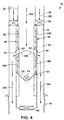
- FIGS. 3-5 highly schematicized drawings of various configurations of the gravel packing assembly 18 in the wellbore 12 are shown, representatively illustrating fluid flows therethrough at corresponding various stages of the method 10.
- FIG. 3 shows the method 10 wherein the gravel packing assembly 18 is being conveyed into the wellbore 12.
- Fluid (indicated by arrows 122) may be flowed from the tubular string 20 through the gravel packing assembly 18, the fluid exiting the float shoe 64 and flowing into the wellbore 12.
- Fluid communication is present between the tubular string 20 and the wellbore 12, permitting positive pressure to be maintained on the filter cake 14.
- the lower sleeve valve 72 of the packer testing device 42 is open, thereby permitting the illustrated fluid flow 122 through the gravel packing assembly 18.
- FIG. 4 shows the method 10 after the packer 22 has been set in the wellbore 12 and the inner portion 28 has been upwardly displaced relative to the outer portion 26.
- the ports 52 are now in fluid communication with the openings 54, thereby providing fluid communication between the tubular string 20 and the lower annulus 34 and permitting positive pressure to be maintained on the filter cake 14 during testing of the packer 22, as indicated by arrows 124.
- the lower sleeve valve 72 of the packer testing device 42 is closed, permitting fluid pressure (indicated by arrows 126) to be applied to the upper annulus 32, without its also being applied to the lower annulus 34.
- the ball 74 and seat 76 of the check valve 68 also prevent fluid flow from the flow passage 40 to the flow passage 44.
- the packer 22 may be tested while maintaining positive pressure on the filter cake 14.
- FIG. 5 shows the method 10 after fluid pressure in the upper annulus 32 has been further increased to apply the predetermined differential pressure across the check valve 68, thereby opening the upper sleeve valve 70, and gravel packing of the lower annulus 34 has commenced.
- a slurry (indicated by arrows 128) may now be flowed from the tubular string 20 into the gravel packing assembly 18, outward through the ports 52 and openings 54, and into the lower annulus 34.
- a fluid portion (indicated by arrows 130) of the slurry 128 may flow through the check valve 68 and upper sleeve valve 70 of the packer testing device 42 and then to the upper annulus 32 for return to the earth's surface.
- the method 10, gravel packing apparatus 18, and packer testing device 42 incorporated therein enable positive fluid pressure to be maintained on the filter cake 14 throughout the completion operation. This substantially reduces the risk of damage to, or collapse of, the formation 16.
- the packer testing device 42 permits fluid communication between the tubular string 20 and the lower annulus 34 during testing of the packer 22 by application of fluid pressure to the upper annulus 32.
Claims (10)
- Procédé de conditionnement d'un puits souterrain dans lequel un puits de forage (12) coupe une formation (16), le procédé comprenant les phases : d'acheminement d'un ensemble (18) dans le puits de forage (12), l'ensemble (18) englobant une garniture (22), une colonne tubulaire (20) engagée dans la garniture (18) et un crible (24) ; d'orientation de la garniture (22) dans le puits de forage (12), divisant alors un premier espace annulaire (32) à partir d'un second espace annulaire (34), le premier espace annulaire et le second espace annulaire (32, 34) étant formés entre l'ensemble (18) et le puits de forage (12), la colonne tubulaire (20) étant disposée à l'intérieur du premier espace annulaire (32) et le crible (24) étant disposé à l'intérieur du second espace annulaire (34), caractérisé en ce que l'appareil (18) comprend en outre un mécanisme de direction d'écoulement (30), le mécanisme de direction d'écoulement (30) permettant un écoulement de fluide longitudinalement à travers l'ensemble (18) pendant l'acheminement dans le puits de forage (12) et le procédé comprenant en outre les phases d'actionnement du mécanisme de direction d'écoulement (30) pour isoler le premier espace annulaire (32) du second espace annulaire (34) tout en permettant une communication fluide entre l'intérieur de la colonne tubulaire (20) et le second espace annulaire (34) et d'actionnement du mécanisme de direction d'écoulement (30) pour permettre une communication fluide entre le second espace annulaire (34) et le premier espace annulaire (32).
- Procédé selon la revendication 1, dans lequel la phase d'actionnement du mécanisme de direction d'écoulement (30) pour isoler le premier espace annulaire (32) consiste en outre à déplacer la colonne tubulaire (20) après la phase d'orientation de la garniture (22).
- Procédé de conditionnement d'un puits souterrain, le puits comportant un puits de forage (12) coupant une formation (16), le procédé comprenant les phases d'acheminement d'un ensemble filtre à gravier (18) dans le puits, l'ensemble filtre à gravier (18) englobant une garniture (22) et un crible de puits (24) fixé à la garniture (22) ; d'orientation de la garniture (22) dans le puits de forage (12), divisant ainsi le puits de forage (12) en une première partie et une seconde partie (32, 34), caractérisé par l'essai de la garniture (22) en appliquant une pression de fluide à la première partie (32) de puits de forage tout en appliquant simultanément une pression de fluide à la seconde partie (34) de puits de forage, externe à l'ensemble filtre à gravier (18).
- Procédé selon la revendication 3, dans lequel la phase d'orientation consiste à disposer une colonne tubulaire (20) fixée à l'ensemble filtre à gravier (18) dans la première partie (32) du puits de forage.
- Appareil que l'on peut disposer de manière opérationnelle à l'intérieur d'un puits souterrain, l'appareil comprenant un logement généralement tubulaire (66) ayant un passage d'écoulement formé à travers celui-ci ; une première valve (68) permettant un écoulement de fluide à travers le passage d'écoulement dans une première direction, mais empêchant l'écoulement de fluide à travers le passage d'écoulement dans une seconde direction opposée à la première direction ; une seconde valve (70) interconnectée à la première valve (68), la seconde valve (70) permettant un écoulement de fluide à travers celui-ci lorsqu'une pression de fluide prédéterminée est appliquée de part et d'autre de la première valve (68) ; et une troisième valve (72) empêchant l'écoulement de fluide à travers celui-ci lorsqu'une partie de celui-ci est déplacée par rapport au logement (66).
- Appareil selon la revendication 5, dans lequel la première valve (68) est un clapet de retenue (68).
- Appareil que l'on peut disposer de manière opérationnelle à l'intérieur d'un puits souterrain, l'appareil comprenant un logement généralement tubulaire (66) ayant un passage d'écoulement formé à travers celui-ci, le passage d'écoulement ayant une première partie et une seconde partie (40, 44) ; un clapet de retenue (68) limitant l'écoulement de fluide entre la première partie et la seconde partie de passage d'écoulement (40, 44) et permettant un écoulement de fluide relativement non limité entre la seconde partie et la première partie de passage d'écoulement (40, 44) ; et une seconde valve (70) permettant et empêchant de manière sélective l'écoulement de fluide entre la première partie et la seconde partie de passage d'écoulement (40, 44) en réaction à la pression de fluide appliquée de part et d'autre du clapet de retenue (68).
- Appareil selon la revendication 7, dans lequel la seconde valve (70) comprend un premier élément et un second élément (114, 106), le premier élément et le second élément (114, 106) se déplaçant l'un par rapport à l'autre lorsqu'une pression de fluide prédéterminée est appliquée de part et d'autre du clapet de retenue (68).
- Appareil servant au conditionnement d'un puits souterrain, l'appareil comprenant une colonne tubulaire (20) ; et un ensemble filtre à gravier (18) engagé dans la colonne tubulaire (20), l'ensemble filtre à gravier (18) englobant une garniture (22) et un crible (24), caractérisé par un dispositif d'essai de garniture (42), le dispositif d'essai de garniture (42) pouvant être configuré de manière sélective pour adopter une première configuration dans laquelle l'écoulement de fluide est permis à partir de la colonne tubulaire (20), puis à travers l'ensemble filtre à gravier (18) interne au crible (24), et une seconde configuration dans laquelle l'écoulement de fluide est bloqué depuis la colonne tubulaire (20) à travers l'ensemble filtre à gravier (18) interne au crible (24).
- Appareil que l'on peut disposer de manière opérationnelle à l'intérieur d'un puits de forage souterrain (12) opposé à une formation (14) coupée par le puits de forage (12), l'appareil comprenant un ensemble (18) ayant une première extrémité opposée et une seconde extrémité opposée et englobant une garniture (22) et un crible (24), caractérisé par un mécanisme de direction d'écoulement (30), le mécanisme de direction d'écoulement (30) permettant une communication fluide longitudinalement à travers l'intérieur de l'ensemble (18) entre la première extrémité opposée et la seconde extrémité opposée lorsque l'ensemble (18) est acheminé dans le puits de forage (12), et permettant et empêchant de manière sélective la communication fluide entre l'intérieur du crible (24) et un premier espace annulaire (32) formé entre l'ensemble (18) et le puits de forage (12) et s'étendant jusqu'à la surface terrestre lorsque la garniture (22) est orientée dans le puits de forage (12).
Applications Claiming Priority (2)
| Application Number | Priority Date | Filing Date | Title |
|---|---|---|---|
| US09/062,785 US6148915A (en) | 1998-04-16 | 1998-04-16 | Apparatus and methods for completing a subterranean well |
| US62785 | 1998-04-16 |
Publications (3)
| Publication Number | Publication Date |
|---|---|
| EP0950794A2 EP0950794A2 (fr) | 1999-10-20 |
| EP0950794A3 EP0950794A3 (fr) | 2001-10-17 |
| EP0950794B1 true EP0950794B1 (fr) | 2004-06-16 |
Family
ID=22044788
Family Applications (1)
| Application Number | Title | Priority Date | Filing Date |
|---|---|---|---|
| EP19990302894 Expired - Lifetime EP0950794B1 (fr) | 1998-04-16 | 1999-04-14 | Dispositif et procédé pour l'équipement de puits souterrain |
Country Status (3)
| Country | Link |
|---|---|
| US (1) | US6148915A (fr) |
| EP (1) | EP0950794B1 (fr) |
| DE (1) | DE69917978T2 (fr) |
Families Citing this family (49)
| Publication number | Priority date | Publication date | Assignee | Title |
|---|---|---|---|---|
| US7124824B2 (en) * | 2000-12-05 | 2006-10-24 | Bj Services Company, U.S.A. | Washpipeless isolation strings and methods for isolation |
| US7201232B2 (en) | 1998-08-21 | 2007-04-10 | Bj Services Company | Washpipeless isolation strings and methods for isolation with object holding service tool |
| US6722440B2 (en) * | 1998-08-21 | 2004-04-20 | Bj Services Company | Multi-zone completion strings and methods for multi-zone completions |
| USRE40648E1 (en) * | 1998-08-21 | 2009-03-10 | Bj Services Company, U.S.A. | System and method for downhole operation using pressure activated valve and sliding sleeve |
| US7198109B2 (en) * | 1998-08-21 | 2007-04-03 | Bj Services Company | Double-pin radial flow valve |
| AU770359B2 (en) * | 1999-02-26 | 2004-02-19 | Shell Internationale Research Maatschappij B.V. | Liner hanger |
| US6575246B2 (en) * | 1999-04-30 | 2003-06-10 | Schlumberger Technology Corporation | Method and apparatus for gravel packing with a pressure maintenance tool |
| US6758277B2 (en) | 2000-01-24 | 2004-07-06 | Shell Oil Company | System and method for fluid flow optimization |
| US6633164B2 (en) | 2000-01-24 | 2003-10-14 | Shell Oil Company | Measuring focused through-casing resistivity using induction chokes and also using well casing as the formation contact electrodes |
| US6679332B2 (en) | 2000-01-24 | 2004-01-20 | Shell Oil Company | Petroleum well having downhole sensors, communication and power |
| US6817412B2 (en) | 2000-01-24 | 2004-11-16 | Shell Oil Company | Method and apparatus for the optimal predistortion of an electromagnetic signal in a downhole communication system |
| US6840316B2 (en) | 2000-01-24 | 2005-01-11 | Shell Oil Company | Tracker injection in a production well |
| US6715550B2 (en) | 2000-01-24 | 2004-04-06 | Shell Oil Company | Controllable gas-lift well and valve |
| US6662875B2 (en) | 2000-01-24 | 2003-12-16 | Shell Oil Company | Induction choke for power distribution in piping structure |
| US6633236B2 (en) | 2000-01-24 | 2003-10-14 | Shell Oil Company | Permanent downhole, wireless, two-way telemetry backbone using redundant repeaters |
| US20020036085A1 (en) | 2000-01-24 | 2002-03-28 | Bass Ronald Marshall | Toroidal choke inductor for wireless communication and control |
| US7114561B2 (en) | 2000-01-24 | 2006-10-03 | Shell Oil Company | Wireless communication using well casing |
| AU4543301A (en) | 2000-03-02 | 2001-09-12 | Shell Oil Co | Controllable production well packer |
| MXPA02008576A (es) | 2000-03-02 | 2003-04-14 | Shell Int Research | Conmutador de barra transversal de potencia y comunicaciones inalambrico. |
| US7073594B2 (en) | 2000-03-02 | 2006-07-11 | Shell Oil Company | Wireless downhole well interval inflow and injection control |
| US7170424B2 (en) * | 2000-03-02 | 2007-01-30 | Shell Oil Company | Oil well casting electrical power pick-off points |
| NZ521122A (en) | 2000-03-02 | 2005-02-25 | Shell Int Research | Wireless downhole measurement and control for optimising gas lift well and field performance |
| MY128294A (en) | 2000-03-02 | 2007-01-31 | Shell Int Research | Use of downhole high pressure gas in a gas-lift well |
| AU4341201A (en) | 2000-03-02 | 2001-09-12 | Shell Oil Co | Electro-hydraulically pressurized downhole valve actuator |
| WO2001065054A1 (fr) * | 2000-03-02 | 2001-09-07 | Shell Internationale Research Maatschappij B.V. | Production d'energie utilisant des batteries avec decharge reconfigurable |
| CA2401681C (fr) * | 2000-03-02 | 2009-10-20 | George Leo Stegemeier | Injection regulee de produit chimique en fond de puits |
| AU5079501A (en) | 2000-03-02 | 2001-09-12 | Shell Oil Co | Wireless downhole well interval inflow and injection control |
| US6457518B1 (en) | 2000-05-05 | 2002-10-01 | Halliburton Energy Services, Inc. | Expandable well screen |
| US7331388B2 (en) * | 2001-08-24 | 2008-02-19 | Bj Services Company | Horizontal single trip system with rotating jetting tool |
| US7017664B2 (en) * | 2001-08-24 | 2006-03-28 | Bj Services Company | Single trip horizontal gravel pack and stimulation system and method |
| US7793721B2 (en) | 2003-03-11 | 2010-09-14 | Eventure Global Technology, Llc | Apparatus for radially expanding and plastically deforming a tubular member |
| US6907936B2 (en) | 2001-11-19 | 2005-06-21 | Packers Plus Energy Services Inc. | Method and apparatus for wellbore fluid treatment |
| US8167047B2 (en) | 2002-08-21 | 2012-05-01 | Packers Plus Energy Services Inc. | Method and apparatus for wellbore fluid treatment |
| US7267990B2 (en) * | 2002-11-15 | 2007-09-11 | Board Of Supervisors Of Louisiana State University And Agricultural And Mechanical College | Chelation of charged and uncharged molecules with porphyrin-based compounds |
| US7886831B2 (en) | 2003-01-22 | 2011-02-15 | Enventure Global Technology, L.L.C. | Apparatus for radially expanding and plastically deforming a tubular member |
| GB2429224B (en) * | 2003-02-18 | 2007-11-28 | Enventure Global Technology | Protective compression and tension sleeves for threaded connections for radially expandable tubular members |
| US7712522B2 (en) | 2003-09-05 | 2010-05-11 | Enventure Global Technology, Llc | Expansion cone and system |
| US7128151B2 (en) * | 2003-11-17 | 2006-10-31 | Baker Hughes Incorporated | Gravel pack crossover tool with single position multi-function capability |
| US7819185B2 (en) | 2004-08-13 | 2010-10-26 | Enventure Global Technology, Llc | Expandable tubular |
| US7258508B2 (en) * | 2005-03-08 | 2007-08-21 | Baker Hughes Incorporated | Annular safety and flow control system for underground gas storage |
| US7523787B2 (en) * | 2005-11-18 | 2009-04-28 | Halliburton Energy Services, Inc. | Reverse out valve for well treatment operations |
| US8056628B2 (en) * | 2006-12-04 | 2011-11-15 | Schlumberger Technology Corporation | System and method for facilitating downhole operations |
| US8245782B2 (en) * | 2007-01-07 | 2012-08-21 | Schlumberger Technology Corporation | Tool and method of performing rigless sand control in multiple zones |
| US8757273B2 (en) | 2008-04-29 | 2014-06-24 | Packers Plus Energy Services Inc. | Downhole sub with hydraulically actuable sleeve valve |
| US8496055B2 (en) * | 2008-12-30 | 2013-07-30 | Schlumberger Technology Corporation | Efficient single trip gravel pack service tool |
| US8403052B2 (en) * | 2011-03-11 | 2013-03-26 | Halliburton Energy Services, Inc. | Flow control screen assembly having remotely disabled reverse flow control capability |
| US9284815B2 (en) | 2012-10-09 | 2016-03-15 | Schlumberger Technology Corporation | Flow restrictor for use in a service tool |
| GB2549021B (en) | 2015-01-13 | 2021-06-16 | Halliburton Energy Services Inc | Downhole pressure maintenance system using reference pressure |
| US10087724B2 (en) | 2016-01-11 | 2018-10-02 | Weatherford Technology Holdings, Llc | Gravel pack manifold and associated systems and methods |
Family Cites Families (6)
| Publication number | Priority date | Publication date | Assignee | Title |
|---|---|---|---|---|
| US3054415A (en) * | 1959-08-03 | 1962-09-18 | Baker Oil Tools Inc | Sleeve valve apparatus |
| US4440218A (en) * | 1981-05-11 | 1984-04-03 | Completion Services, Inc. | Slurry up particulate placement tool |
| US4478286A (en) * | 1983-02-14 | 1984-10-23 | Baker Oil Tools, Inc. | Equalizing valve for subterranean wells |
| US4889199A (en) * | 1987-05-27 | 1989-12-26 | Lee Paul B | Downhole valve for use when drilling an oil or gas well |
| US5609204A (en) * | 1995-01-05 | 1997-03-11 | Osca, Inc. | Isolation system and gravel pack assembly |
| US5579844A (en) * | 1995-02-13 | 1996-12-03 | Osca, Inc. | Single trip open hole well completion system and method |
-
1998
- 1998-04-16 US US09/062,785 patent/US6148915A/en not_active Expired - Lifetime
-
1999
- 1999-04-14 DE DE1999617978 patent/DE69917978T2/de not_active Expired - Fee Related
- 1999-04-14 EP EP19990302894 patent/EP0950794B1/fr not_active Expired - Lifetime
Also Published As
| Publication number | Publication date |
|---|---|
| DE69917978T2 (de) | 2004-10-21 |
| EP0950794A2 (fr) | 1999-10-20 |
| US6148915A (en) | 2000-11-21 |
| DE69917978D1 (de) | 2004-07-22 |
| EP0950794A3 (fr) | 2001-10-17 |
Similar Documents
| Publication | Publication Date | Title |
|---|---|---|
| EP0950794B1 (fr) | Dispositif et procédé pour l'équipement de puits souterrain | |
| US5921318A (en) | Method and apparatus for treating multiple production zones | |
| US8127845B2 (en) | Methods and systems for completing multi-zone openhole formations | |
| US8267173B2 (en) | Open hole completion apparatus and method for use of same | |
| US7337840B2 (en) | One trip liner conveyed gravel packing and cementing system | |
| US6575243B2 (en) | Zonal isolation tool with same trip pressure test | |
| US7451816B2 (en) | Washpipeless frac pack system | |
| AU2011341561B2 (en) | Packer for alternate flow channel gravel packing and method for completing a wellbore | |
| US6446729B1 (en) | Sand control method and apparatus | |
| US7066264B2 (en) | Method and apparatus for treating a subterranean formation | |
| US7191833B2 (en) | Sand control screen assembly having fluid loss control capability and method for use of same | |
| AU761225B2 (en) | Apparatus and method for open hole gravel packing | |
| CA1246989A (fr) | Filtre a gravier | |
| US4583593A (en) | Hydraulically activated liner setting device | |
| AU2018230986B2 (en) | Liner conveyed compliant screen system | |
| GB2395210A (en) | Wellbore junction liner | |
| US6241013B1 (en) | One-trip squeeze pack system and method of use | |
| US8011433B2 (en) | Bidirectional gravel packing in subterranean wells | |
| OA16457A (en) | Packer for alternate flow channel gravel packing and method for completing a wellbore. |
Legal Events
| Date | Code | Title | Description |
|---|---|---|---|
| PUAI | Public reference made under article 153(3) epc to a published international application that has entered the european phase |
Free format text: ORIGINAL CODE: 0009012 |
|
| AK | Designated contracting states |
Kind code of ref document: A2 Designated state(s): AT BE CH CY DE DK ES FI FR GB GR IE IT LI LU MC NL PT SE Kind code of ref document: A2 Designated state(s): DE FR GB NL |
|
| AX | Request for extension of the european patent |
Free format text: AL;LT;LV;MK;RO;SI |
|
| PUAL | Search report despatched |
Free format text: ORIGINAL CODE: 0009013 |
|
| AK | Designated contracting states |
Kind code of ref document: A3 Designated state(s): AT BE CH CY DE DK ES FI FR GB GR IE IT LI LU MC NL PT SE |
|
| AX | Request for extension of the european patent |
Free format text: AL;LT;LV;MK;RO;SI |
|
| 17P | Request for examination filed |
Effective date: 20020201 |
|
| AKX | Designation fees paid |
Free format text: DE FR GB NL |
|
| 17Q | First examination report despatched |
Effective date: 20020819 |
|
| GRAH | Despatch of communication of intention to grant a patent |
Free format text: ORIGINAL CODE: EPIDOS IGRA |
|
| GRAP | Despatch of communication of intention to grant a patent |
Free format text: ORIGINAL CODE: EPIDOSNIGR1 |
|
| GRAS | Grant fee paid |
Free format text: ORIGINAL CODE: EPIDOSNIGR3 |
|
| GRAA | (expected) grant |
Free format text: ORIGINAL CODE: 0009210 |
|
| AK | Designated contracting states |
Kind code of ref document: B1 Designated state(s): DE FR GB NL |
|
| REG | Reference to a national code |
Ref country code: GB Ref legal event code: FG4D |
|
| REF | Corresponds to: |
Ref document number: 69917978 Country of ref document: DE Date of ref document: 20040722 Kind code of ref document: P |
|
| ET | Fr: translation filed | ||
| PLBE | No opposition filed within time limit |
Free format text: ORIGINAL CODE: 0009261 |
|
| STAA | Information on the status of an ep patent application or granted ep patent |
Free format text: STATUS: NO OPPOSITION FILED WITHIN TIME LIMIT |
|
| 26N | No opposition filed |
Effective date: 20050317 |
|
| PG25 | Lapsed in a contracting state [announced via postgrant information from national office to epo] |
Ref country code: NL Free format text: LAPSE BECAUSE OF NON-PAYMENT OF DUE FEES Effective date: 20051101 Ref country code: DE Free format text: LAPSE BECAUSE OF NON-PAYMENT OF DUE FEES Effective date: 20051101 |
|
| PG25 | Lapsed in a contracting state [announced via postgrant information from national office to epo] |
Ref country code: FR Free format text: LAPSE BECAUSE OF NON-PAYMENT OF DUE FEES Effective date: 20051230 |
|
| NLV4 | Nl: lapsed or anulled due to non-payment of the annual fee |
Effective date: 20051101 |
|
| REG | Reference to a national code |
Ref country code: FR Ref legal event code: ST Effective date: 20051230 |
|
| PGFP | Annual fee paid to national office [announced via postgrant information from national office to epo] |
Ref country code: GB Payment date: 20180308 Year of fee payment: 20 |
|
| REG | Reference to a national code |
Ref country code: GB Ref legal event code: PE20 Expiry date: 20190413 |
|
| PG25 | Lapsed in a contracting state [announced via postgrant information from national office to epo] |
Ref country code: GB Free format text: LAPSE BECAUSE OF EXPIRATION OF PROTECTION Effective date: 20190413 |